WouterJD / FortiusANT

FortiusANT enables a pre-smart Tacx trainer (usb- or ANT-connected) to communicate with TrainerRoad, Rouvy or Zwift through ANT or Bluetooth LE.
GNU General Public License v3.0
145 stars 78 forks source link

Power curve support Tacx Flow&Magic T2020 #153

Closed jurgen-iflow closed 3 years ago

jurgen-iflow commented 3 years ago

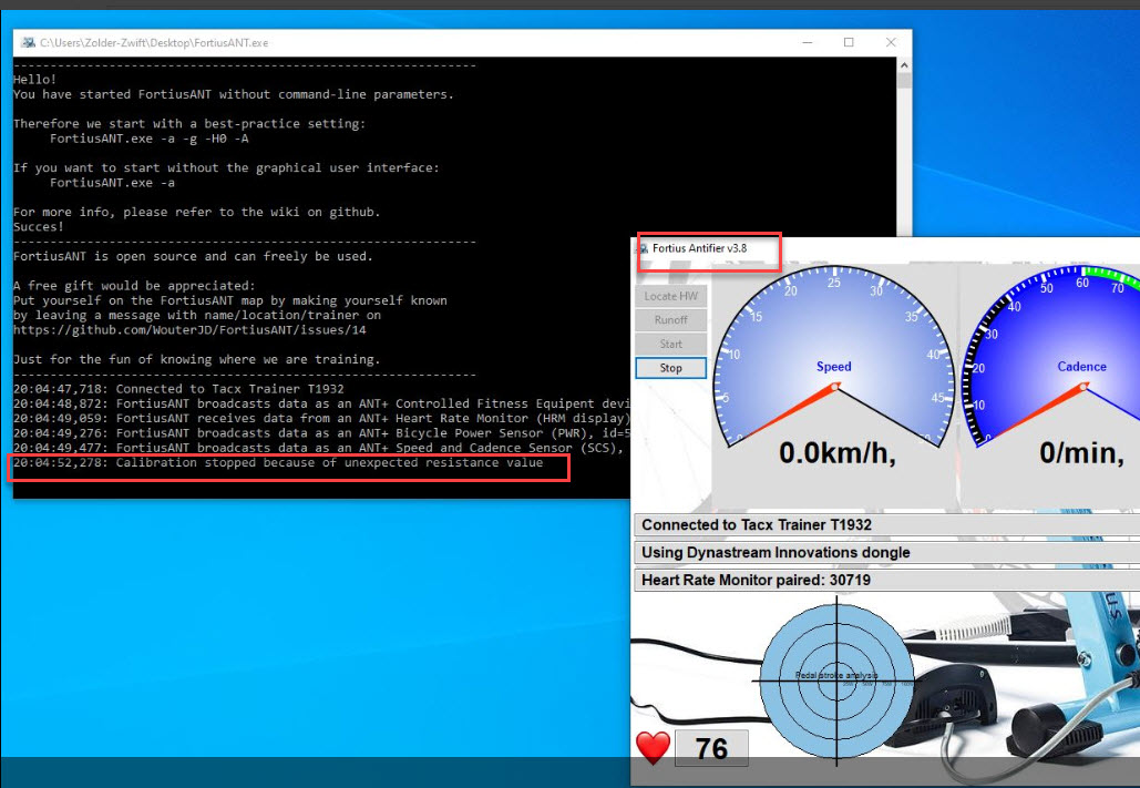
hello Wouter , is it possible to have a correct powercurve for the Tacx Flow T2250 , the current powercurve is far off and i could not find a good way to adjust it to my Garmin vector 2 powermeter reading

What i noticed , see screenshot is that the calibration of my Flow motor give an error during initialization "calibration stopped because of unexpected resistance value
tacxflow-fortiusant by FortiusAnt

grt jurgen

cyclingflow commented 3 years ago

You have to switch off calibration (-n)

We are working on the power curve. I have a fork, with adapted power curves for i-Flow and i-Magic https://github.com/cyclingflow/FortiusANT/releases You might want to try that. Please, use the included .bat files, they will specify the correct command line parameters.

Discussion is in https://github.com/WouterJD/FortiusANT/issues/143

BTW. I have recently increased the tire resistance to prevent slipping. (mine now has a calibration factor of 5 on the manual control unit) so, the curves are calibrated a bit above the normal low settings of your flow. Of course it depends on your tire pressure and knob setting.

WouterJD commented 3 years ago

@jurgen-iflow Welcome to the FortiusANT community


I'm always curious to know who I communicate with, where FortiusANT is used and what configuration is used. Please tell me what brake and what head unit do you use, the bundle apparently=T2250? Where are you from?


Thanks @cyclingflow; a Flow-compatible version will be available shortly.

Jurgen, I see you have a powermeter and that will be great to do some tests. Will be back soon

WouterJD commented 3 years ago

@jurgen-iflow Please try the version in https://github.com/WouterJD/FortiusANT/tree/%23143-Powercurve-iMagic The correct title for the branche would be "Magnetic brake"; but what's in a name.

@cyclingflow This version implements formula's instead of tables

@bikebeppe64 Perhaps you can do a testride with the uploaded version.

See uploaded manual for description; also "FortiusANT - Powercurve.xlsm" has a tab for the Magnetic Brake.

cyclingflow commented 3 years ago

I hope @BikeBeppe64 will enjoy the experience!

And it is great to have automatic detection of the brake unit.

@WouterJD I have some comments regarding your manual and implementation that i will put in another thread.

Mk2mark commented 3 years ago

Thanks for you message. Yes I do have a power meter.

jurgen-iflow commented 3 years ago

I'm always curious to know who I communicate with, where FortiusANT is used and what configuration is used. Please tell me what brake and what head unit do you use, the bundle apparently=T2250? Brake 1901 headunit 1932 Where are you from? Netherlands ( near Eindhoven )

i will try the power curve-Imagic tonight

WouterJD commented 3 years ago

@Mk2mark, @jurgen-iflow

... adjust it to my Garmin vector 2 powermeter reading ... ... Yes I do have a power meter ...

To know the relation between resistance and power, I would really appreciate it if you would execute the following test:

The test is performed as follows:

Would be very helpful

Mk2mark commented 3 years ago

Will try to do that tomorrow. Do I need a newer version of the code?

Today on Zwift I was overtaken by J Wouter as approaching London Bridge - was that you?

WouterJD commented 3 years ago

The version in the current branch is good to execute this test.

Mind to use the version in https://github.com/WouterJD/FortiusANT/tree/%23143-Powercurve-iMagic The correct title for the branche would be "Magnetic brake"; but what's in a name.

Further developments can be done with described test-results, upon which the power curve will be based. Succes!

No; that was not me. Currently either riding outside or Trainer Road for structured training. See you on strava

jurgen-iflow commented 3 years ago

Hi , i got stucked on increasing Targetpower on the headunit , looks like my headunit is not responding only on "cancel" as you can see i installed the "version3.9 with the parameters -a -g -d127 -r -m , but could not select targetpower ? please guide me were to do that

image

cyclingflow commented 3 years ago

I dont see it. It does say 'manual power' but the power display suggests "grade mode". Something is off.

Well may be. Just to be sure: did you use lowercase -m switch? case makes a difference

cyclingflow commented 3 years ago

I planned on commenting on some of the progress, but i came across an issue this afternoon that really puzzled me. May be well well know by you guys.

1932 unit issue: wrong configuration.

The program was not working correctly at all, which i did not understand, until i remebered i switched 1932 head-units. Luckely i wrote down the serial numbers given by the interface, so i could check.

What was really confusing: It turns out, i got an used 1932 with an i-flow, that says 'fortius' on the back, and is working perfectly well with the flow. Incidentally, i got an used 1932 with the Fortius motorbrake without powersupply that says 'VR-interface' on the back.

This one gave the wrong results. Speed was too low, and some resistance values also seemd off. Power was more off, than just the difference in speed could explain.

So apparently, you can setup these 1932 devices for any of the brakes, but you have to do so first. I presume through the original software. I'am not aware if i can do so through FortiusAnt.

Makes sense, because for example the motorbrake has a different roll-diameter, than the magnetic brake..

Just wanted to note that this may account for some of the users getting strange results. Please fill me in, if i have missed something obvious.

switchabl commented 3 years ago

@cyclingflow That is very strange. I have never seen anything to suggest that TTS configures the brake type in any way in the USB traffic. As far as I am aware, 1) the head unit detects the magnetic brake from the 50/60Hz input on pin 4 and 2) the software requests the brake serial/version and knows that a magnetic brake is connected if it gets all zeroes (the magnetic brake is completely analog and can not send a serial number). That being said, I only have a T1932 labelled "Fortius". It was included with an i-Flow bundle and works fine with either magnetic or motor brakes. Maybe they have different firmware versions? The head unit firmware version is sent over USB, but I am not sure if FortiusANT displays it.

switchabl commented 3 years ago

I don't have my Flow unit here right now (haven't used it in years), so I can't do any measurements myself. But I was playing a bit with TTS and simulating the brake by feeding a 50Hz signal and a wheel speed signal from a function generator into the head unit. I was trying to reconstruct the power curves used by TTS, but the results are ... confusing. So I cannot share those (yet) without more tests without maybe having to retract something later.

But I did find some interesting bits of information:

cyclingflow commented 3 years ago

I thought it did, last time i looked. Have not looked at latest version perhaps. @WouterJD was using part of my implementation/antifier using tables with these discrete values. Note that there is a difference between the scale of the values send, and returned. (And just i minor note: it only changes these values to say 1559, if there is wheelspeed. Otherwise it appears to stay at 1039)

I can confirm that the correct factor for the speed in km/h is indeed 289.75

I agree. I have only used a different value for backwards compatability with antifiers tables. And changed my bike computer accordingly. Comparison with the T1682 would suggest the same.

It does not include include rolling resistance and the speed-dependence of the force. Those are calculated in software.

I think this is a crucial point. I have mathematical ideas for adding an additonal term to the model, and some possibly nice results. However, i'am not sure @Wouter would like to go along a more complicated route, if the current models give reasonable results. I might be on my own there. NP.

All models can be expressed as a hierarchical series of of models, have a few more or less parameters. They are either all right or all wrong, conceptually. And they are also the same as the legacy approach. There are just some differences in accuracy, due to using more parameters/terms. Same goes for slight differences in estimation procedures. IF everything would perfect, the solutions would coincide. No new data will change these mathematical facts. Moreover, it is hard to conceive of measurement errors such that resampling would break the emerging patterns.

Adding a new term however, might be very relevant. The big issue IMHO is, that the actual tire resistance gives hugely different results. For me, between sessions, but also between me and other users. It also makes it impossible to truly interpret any differences between users, because resistance is unknown. We do need some calibration factor/procedure.

For example, the table i'm planning to provide to @WouterJD with, that includes all my calibration runs, is already outdated for my use, because i have increased tire resistance.

Therefor, for the immediate future, i'am working on getting the powerreadings out of the T1682. Tedious job. But it gets rid of any differences between sessions and users, due to tire resistance. Once you have set the unit to a particular calibration factor, readings are consistent, whether you deflate the tire or not, as long as the bikewheel is driving the trainer. This will proceduce a table of speeds vs power, for all resistance levels.

We may acquire readings for more than one calibration level, and some hints how to setup you trainer and bike, such that once you have completed a run-off, we know what table to use, that can be reasonably reproduced by current models/formula's. This should give users power estimates within the same range of accuracy as the non-usb trainers. Well, maybe :-)

I'am thinking of something more intricate, but that's for my fun.

switchabl commented 3 years ago

I also have some conceptual thoughts that can maybe help clear some things up. From what I can see, this is the model that is currently being considered:

if Resistance < 1819: Factor = Factor - (1819 - Resistance) / 15
return int( ( (SpeedKmh / Factor) + (1 / Offset) ) * Resistance)

There are several reasons to believe that, even if you manage to fit this reasonably well to a limited data set, it may not generalize well to different speeds and other people's trainers.

If I wanted to build a model for this, I would start from the basic physics: we can express the power in terms of the wheel speed and the various forces acting on the wheel

power = speed * (brake force + rolling resistance + flywheel force)

(The flywheel force is non-zero only when accelerating and deccelerating. It should eventually be included, but ignore for now.)

The rolling resistance is usually assumed to be independent of speed, but it is highly dependent on the tyre used, the tyre pressure and unfortunately temperature (both through the tyre material and because the pressure increases when it gets hot). Every wheel-on smart trainer I am aware of uses some form of run-down calibration to calculate this. A typical value might be ~2.5N, but this can vary a lot.

The brake force is where it gets complicated. Eddy current brakes are notoriously hard to model, in particular across large speed ranges. So some sort of approximation is needed. The crudest possible one would be to assume that it is constant for each resistance setting. This seems to be what TTS does for higher speeds:

power (W) = speed (km/h) / 3.6 * (raw force (bytes 38-39) / 100 + rolling resistance (in N))

I am not entirely sure what TTS does for low speeds. It looks like it could come from a calibration table.

For low speeds, it is known that the brake force grows linearly with speed (-> power grows quadratically). Potential models to try that include this effect:

I would love to experiment with this to see what works, but I would need the data for this. I have looked in the other issue and @cyclingflow seems to have done a lot of work there, but I didn't find any raw data (maybe I missed something?). It would be good to have not only power readings for all the resistance settings, but also at least some with a detailed set of different speeds.

switchabl commented 3 years ago

Therefor, for the immediate future, i'am working on getting the powerreadings out of the T1682. Tedious job. But it gets rid of any differences between sessions and users, due to tire resistance. Once you have set the unit to a particular calibration factor, readings are consistent, whether you deflate the tire or not, as long as the bikewheel is driving the trainer. This will proceduce a table of speeds vs power, for all resistance levels.

Yes, this is what I tried to do with TTS4. It's less tedious because you can just automate it. I have collected a relatively large dataset, but some it looks quite messy, so either something went wrong or the Tacx implementation is just weird. I would not be totally surprised if it is, but in that case it may be less useful than we hope.

I should also stress that I am not in favour of introducing many new parameters and look-up-tables (even if it does turn out Tacx did). That will work perfectly for exactly one session. I am interested in a model that is as simple as possible (but no simpler) and allows for a single parameter run-down calibration to account for tyre pressure etc. so it will work reasonably well for everyone.

Mk2mark commented 3 years ago
  • Start FortiusANT with the following command-line parameters: -a -g -d127 -r -m (autostart, gui, logfile, resistance, manual power)

  • FortiusANT is operated in manual mode (-m flag), modifying the target power from 10...4000 in 50 Watt steps (read next step!).

  • The power as selected is transferred directly to the trainer (Resistance = TargetPower) without intermediate formula. (The -r flag is created for this purpose). The assumption is that the allowed resistance for the i-Flow ranges from 1000…4000 and that is not Watts!

  • Initial TargetPower in FortiusANT is 100Watt (--> Resistance = 100)

When i do this it always starts up at 2% grade and the headhunt up/down has no effect. The readout gives back power as pedalled. I have tried various flag settings (-m / -M / -n) and they all behave exactly the same.

WouterJD commented 3 years ago

@Mk2mark please provide logfile, so I can check. Also mind that there are no CTP's (Zwift, Rouvy, Trainer Road) active; they might send commands.

WouterJD commented 3 years ago

but could not select targetpower

Use the headunit: UP/DOWN buttons

WouterJD commented 3 years ago

All; thanks for the enthusiastic participation in this thread. I am convinced we will get to a clear implementation. I'm reading all posts and will do my best to integrate.

Some points from my side:

Mk2mark commented 3 years ago

Log files attached. There is no CTP connected. FortiusANT.2020-12-01 09-59-30.log FortiusAntGUI.2020-12-01 09-59-31.log cannot attach json file.

WouterJD commented 3 years ago

The head unit firmware version is sent over USB, but I am not sure if FortiusANT displays it.

Since recent, I detect motor brake version and display it on console and in the logfile.

switchabl commented 3 years ago
* Who can explain why there are 14 distinct resistance values? Is that also true for the T1902 (legacy) headunit?

To remove any doubt: it sends only 14 different values to the brake too, it is not just what it reports back. I checked with an oscilloscope. This means we really only need to test 14 different settings when collecting data and nothing in between! Why? We will never be sure. Technically the brake itself could do anything in between. My guess: the head unit has a calibration table. It uses the closest resistance where it knows the calibrated force value to return. If they did this well, it could make our work a bit easier (because what we get is already somewhat calibrated). If not: big mess...

I don't have a T1902. But from the curve in the manual it seems to change continuously? So, no? Maybe I can load the T1902 firmware onto my old T1942 and test with that.

* Let's create a measured power curve first: what power is required for the TargetResistance (at some speed)?

Yes, I think we can all agree on this. The phsyics can give us a starting point, suggest some sensible things to try (and reject bad ones). But without data, there is nothing more I can do right now either.

switchabl commented 3 years ago

A couple of notes on the test protocol:

WouterJD commented 3 years ago

Log files attached. There is no CTP connected. FortiusANT.2020-12-01 09-59-30.log FortiusAntGUI.2020-12-01 09-59-31.log cannot attach json file.

Sorry; bad version. I have repaired and the current version should work.

WouterJD commented 3 years ago
  • I can confirm that the correct factor for the speed in km/h is indeed 289.75

I have set this value in the current version, since it will influence the measurements and / or powercurve.

cyclingflow commented 3 years ago

@switchabl

There really needs to be a 5-10 minutes warm-up at the start

I have done so. It is one of the reasons i repeated some of the runs. Including the spin downs (i have actually also simply reversed the scheme, going from high speeds to low speeds.) I have to say, there is little or none indication of the warmup effect, and reversed scheme effects. Tire pressure and knob-resistance have much bigger influence in my experience.

Regarding a 'continuous' spin down or spin up: I was doing so, because it was the way power_curve.py from antifier was requesting. However, it is very difficult to interpret, because the acceleration of the flywheel comes into play. Together with the inaccuracy of power_curve.py getting my power readings, it made me stop doing these runs.

More speed values would be nice

I started doing so. See my post with the table. IMHO they are not needed, except may be for catching some slight non-linear effects at really high speeds. I can't do them anyway.

WouterJD commented 3 years ago
  • Because I could control the wheel speed signal directly (and very accurately), I can confirm that the correct factor for the speed in km/h is indeed 289.75 (knowing that there are 4 pulses per revolution and assuming the spindle has a diameter of 29mm)

I believe the factor of 289.75 is correct; no issue there and let's stick to it. But what is the unit of measurement? I ever read (do not remember where) that it would be mm/sec.

cyclingflow commented 3 years ago

why 14 distinct values

Why? We will never be sure. Technically the brake itself could do anything in between. My guess: the head unit has a calibration table. It uses the closest resistance where it knows the calibrated force value to return. If they did this well, it could make our work a bit easier (because what we get is already somewhat calibrated). If not: big mess...

They did. The plots i made and showed early on suggest everything is very linear. And really easy to fit. It's probably also because of what you said: eddy currents notoriously difficult to model.

cyclingflow commented 3 years ago

@switchabl

For low speeds, it is known that the brake force grows linearly with speed (-> power grows quadratically). Potential models to try that include this effect: 1. piece-wise linear with two parts: one below ~10km/h that grows linearly and then a ~constant part

  1. something that interpolates between a linear growth and the 1/speed dependency that eventually happens at very high speeds (but we may not ever reach this), as suggested by Wouterse (https://doi.org/10.1049/IP-B.1991.0019 ; sorry about the pay-wall, but the paper itself is probably not too helpful anyway)

That's exactly what i implemented in my approach: a piece wise linear approach to deal with low speeds. Above 10kph everything is fine with another lienar approach.

\your comment on the distinct values and fitting those\

This is exactly the approach taken by antifier. Just fit 14 equations. Poweri = constant i Resistance_i Speed + offset_i. The offset is needed because of the non-linearity at low speeds (effectively: resistance is not constant at that point. At higher speeds, it appearently is. I'am quite sure, antifier did expect some non-linear effects, as i did. In his code you can see he started out with curve-fitting, which is telling. After making plots he will have concluded as i did, that a linear fit above 10 kph is almost perfect.

Note: what seems to be confusing is, that the factors in antifiers equations are not resistance values, but they can be easily rephrased to be so. So no conceptual change here IMHO

So i thought, job done. Easy to implement, and has been working fine for me since.

Now, @WouterJD objected to this approach. He prefers a single formula. (Several arguments for this point of view) And the point is: the constant_i factors are linear related. Unfortunately, the offsets are not. So, at that point given the approach taken by @WouterJD for lagacy trainers, I implemented a 5 factor approach, two linear factors that estimate the constant_i's, and 3 factors, including a quadratic term, to estimate the offset_i 's (using matlab and a global optimal solution in the LS framework, rather than fitting slopes and offsets seperately).

Slightly less accurate, but may be more conveniently put into the type of formula's @WouterJD prefers. So i still thought job done. Fitting a actual measured table is not hard.

However, producing consistent tables is. Or having different riders produce comparable results. Because the power is too strongly dependent on tire resitance.

WouterJD commented 3 years ago
  • The test can be made faster by going through the relevant values only

Agree. I would have to implement the 14-steps (instead of +/- 50). Did not do that, because of time (and required testing). Note that @bikebeppe64's test (using the -r flag) first showed that a floating resistance is translated into 14 discrete steps by the headunit (untill that time unknown to me). OK it avoids pressing the headunit buttons 80 times; but I hope it's ot too much a problem.

switchabl commented 3 years ago

Ah, I see. If you have enough data at different speeds already to show it is sufficiently linear, that is probably good enough. The region below ~10km/h is where we expect the biggest deviations anyway and this will be 1) harder to test and 2) probably not as important.

My experience with the Fortius and Genius has been that temperature drift affected the results by maybe 10%. But not the same for all resistance ranges and easily avoided.

I think you mean something else by "spin-down". Let me clarify: what I am suggesting is to pedal up to 30-40km/h, then stop pedalling and let the wheel slowly come to stop (at lowest resistance setting). The time->speed curve allows to estimate the rolling resistance (if the inertia of the wheel/flywheel is known). It should not take more than a few seconds.

WouterJD commented 3 years ago

I am not entirely sure what TTS does for low speeds. It looks like it could come from a calibration table. ... and further ...

My experience with the Fortius T1942 motorbrake is that low wheel speeds are not really feasible. I always ride in highest gear (==> highest possible wheelspeed). If that would be the same for the Flow/Magic then any optimization for low wheelspeeds is useless. This also led to the virtual gearbox; keep wheelspeed high and reduce resistance. Also note that we may create a really good algorithm, but apparently Tacx did not put much effort in it and simple uses 14 levels (for unknown reason so far).

WouterJD commented 3 years ago

It would be good to have not only power readings for all the resistance settings, but also at least some with a detailed set of different speeds.

That is exactly the test @Mk2mark is going to do. That is exactly what @yegorvin has done to establish the powercurve for the T1902 headunit.

Well enough for now; I'm curious to receive the raw data.

WouterJD commented 3 years ago

My experience with the Fortius and Genius has been that temperature drift affected the results by maybe 10%

Nice to know; if our algorithm gets somewhere near (5% for example) to the measured powercurve ; we're as close as we can get. My impression is that the trainers (at that time) were made to do some VR. Before the time of power-meters, nobody knew that the trainer deviated from what the display said. We now use the trainer with power-meter and Zwift; which is far beyond what they were designed for - and likely beyond the trainer's precision and repeatability.

Having said that: still going for max result :-)

cyclingflow commented 3 years ago

Our post are crossing, because of me taking time to edit posts. Makes it harder to read.

Having said that: still going for max result :-)

Good to know. I a'm thinking of adding a term for tire resistance, like @switchabl formula for power. This also explains the success of antfier approach: because fitting 14 separate equations, makes the tire-resistance_term disappear into one of the two constants, depending on whether you model tire resistance to be indepedent of speed, or slightly dependent of speed. I have seems formula's of that.

switchabl commented 3 years ago

@WouterJD The magnetic brakes have no issues running at low speed. No "slipping" or roughness. But I think even on the highest setting the power would be quite low. So not many people may use it in practice.

Accuracy-wise I think 10% is probably the best you can hope for without direct-drive because of the whole tyre/pressure/temperature thing. It seems to be what I get with the Genius if I warm-up and then run the internal calibration. (The new Smart Vortex is also specified at 10%). I think the aim should be that the error introduce by the model does not add much to that figure.

@cyclingflow I hope that some of the problem will go away if we fit the brake force rather than power and add a separate rolling resistance term. I will do some tests with your data.

In general, I am not convinced by a 2x14 parameter approach unless we have data to support 1) it is really necessary and 2) very consistent across sessions and different trainers. For someone who can do the complete individual characterization it may well be very accurate. But if other people try to use the same coefficients, it will likely turn out to be a case of overfitting.

cyclingflow commented 3 years ago

In general, I am not convinced by a 2x14 parameter approach...

The 14 offsets appear to be non-linearly related. Rather ugly to find a close-form formula for. The 14 parameters for 'slope' are just a slightly different value for resistance as compared to the ones provided by the brake/headunit. All not a big deal. 5 factors approximation amount to almost similar accuracy.

Rolling Resistance i have sofar taken the rolling resistance formula from this website https://www.bicyclerollingresistance.com/cx-gravel-reviews/schwalbe-g-one-allround#rr If you scroll down you will find

Use the formula: RR (Watts) = CRR speed (m/s) load (N) t

cyclingflow commented 3 years ago

@switchabl

Was waiting for that argument. :-)

I think it is based up on a to general application of generalization and resampling theory. I wont get into that.

Just look at the plots you no-doubt will make, and ask yourself: what measurement model or resampling model would allow the line for the speed vs power to be fitted so accurately, while allowing such a huge measurement error in the offsets, that they look curve linear related to resistance, while they truly are linear related?

I don't see it. Sure, with new measurements they'll smooth out, no doubt.

The offsets are probably just defined by the non-linear start of the 'curve' just as you explained. And you have to deal with that. Not neccesarily with 14 equations though. It's just brutally efficient. But i don't mind if one would come up with a equation that fit's it, based upon physics. Would be great.

The big measurement errors are due to rolling resistance. If I change the resistance each line moves considerately.

switchabl commented 3 years ago

Was waiting for that argument. :-)

I think it is based up on a to general application of generalization and resampling theory. I wont get into that.

Ha, well, with a sample size of N=1 trainers my analysis would be on rather shaky theoretical ground in any case. Unless Tacx donates an internal dataset from 30 trainers under different conditions tommorow, there is probably little cause to discuss this in earnest. For now, it is really just my heuristic take: if you had a box of bent-out-of-shape rulers with the tick labels missing and someone took just one, examined it closely and told you "these are actually quite accurate with a 24 parameter calibration", you would probably need some convincing. Yes I know, it is a gross exaggeration and it may turn out that there is reason to believe they are all bent in the same way. But I am sure you understand the sentiment.

Anyway, I will now take a closer look at the data myself and hopefully have a better understanding afterwards.

cyclingflow commented 3 years ago

Yes I know, it is a gross exaggeration and it may turn out that there is reason to believe they are all bent in the same way. But I am sure you understand the sentiment.

I laughed. Thx :-)

WouterJD commented 3 years ago

OK; I will admit - I'd rather have a formula than a table and -as stated earlier- I would like to see a sort of evidence for the content of the table. Note also that lots of people have been struggling with the power curve file in the past (and now we are). I'm afraid that we're put on the wrong leg, starting off with the complex code without explanation.

Most important thing is: the table works (for the T1932/T1901 combi). And that's the primary goal - to support @SpunkyOZ @BikeBeppe64 @SwitchMcBlade @Timmenem @Lorangaw @e7andy @Mk2mark @tjerkh @sgtjlanc @SpeedColumbus @cyclingflow @jurgen-iflow and all others who all have the T1932 with a T1901 magnetic brake.

What I did this evening is adopt the tables and see what can be made of it; starting with CyclingFlow's code (thanks) - port it to Excel and see what it all does. See for results below, numerically; no graphs.

image

image

image

image

The latter is the result of the next two functions (in VBA, which will not be an issue - I hope), where PowerCurve() is the table of the first picture. No curve-formula's; table-driven. [The third function does the reverse]

Function calcPower_usbMB(ResistanceLevel, SpeedKmh) As Double
    calcPower_usbMB = SpeedKmh * PowerCurve(Factor, ResistanceLevel) + PowerCurve(Offset, ResistanceLevel)
    If calcPower_usbMB < 0 Then calcPower_usbMB = 0
End Function
Public Function CurrentResistance2Power_usbMB(CurrentResistance, SpeedKmh) As Double
    Dim ResistanceLevel As Integer
    For ResistanceLevel = low To high
        If CurrentResistance = low Or _
           ResistanceLevel = high Or _
           PowerCurve(Resistance, ResistanceLevel) >= CurrentResistance Then
           Exit For
        End If
    Next ResistanceLevel
    CurrentResistance2Power_usbMB = calcPower_usbMB(ResistanceLevel, SpeedKmh)
End Function
Function TargetPower2Resistance_usbMB(TargetPower, SpeedKmh) As Double
    Dim ResistanceLevel
    Dim p
    For ResistanceLevel = low To high
        p = calcPower_usbMB(**send**ResistanceLevel, SpeedKmh)                  [edited]
        If ResistanceLevel = high Or p >= TargetPower Then
            Exit For
        End If
    Next ResistanceLevel
    TargetPower2Resistance_usbMB = PowerCurve(Resistance, ResistanceLevel)
End Function

My questions at this moment:

Attached the zipped excel sheet to play with and comment.

The last tables, in case you might not have access to Excel: image

image

image

WouterJD commented 3 years ago

I hope that some of the problem will go away if we fit the brake force rather than power and add a separate rolling resistance term. I will do some tests with your data.

Please keep in mind that CTP's provide TargetPower or TargetGrade and we will have to convert Power2Resistance() or Grade2Resistance(), providing it to the head-unit's 14-step USB-interface. [I leave grade-mode aside for the time being so that we agree on PowerMode first]

In general, I am not convinced by a 2x14 parameter approach unless we have data to support 1) it is really necessary and 2) very consistent across sessions and different trainers. For someone who can do the complete individual characterization it may well be very accurate. But if other people try to use the same coefficients, it will likely turn out to be a case of overfitting.

Agree, as stated before, most people want to install and ride. Have fun. So let's keep it simple; it's complex enough with libusb and two dongles.

WouterJD commented 3 years ago

Use the formula: RR (Watts) = CRR speed (m/s) load (N) t

@cyclingflow I agree on that and this is what is currently happening, funny enough divided into 14 different formula's per range: calcPower_usbMB = SpeedKmh * PowerCurveFactor + PowerCurveOffset

WouterJD commented 3 years ago

And you have to deal with that. Not necessarily with 14 equations though. It's just brutally efficient. But i don't mind if one would come up with a equation that fit's it, based upon physics.

We're moving into the same direction; when the questions in the post above are answered; I will port the functions to Python and create a version to be tested.

WouterJD commented 3 years ago

This issue continues the work of #143; source material can be found there.

switchabl commented 3 years ago

Ok, I think I now have a somewhat better understanding of what is happening. Here is a plot of speed vs force, not power (force was calculated using force = power / speed). This is the more natural quantity to look at from a physics point of view. force_curve

WouterJD commented 3 years ago
  • I can confirm that the correct factor for the speed in km/h is indeed 289.75 (knowing that there are 4 pulses per revolution and assuming the spindle has a diameter of 29mm)

What is the formula for the 289.75 factor? (Just for my curiosity)

WouterJD commented 3 years ago
  • The target values and the force values do not live on the same scale:

Below is the result from @bikebeppe64's test (nov 25th). I understood that the TargetResistance is translated into 14 distinct values, but missed that it's not the same range; sorry!

image

image

So when SENDING; the second resistance must be used from the table (1900-3750) But when RECEIVING the first resistance must be inspected (1039-4677) image

So the formula Power2Resistance() and Resistance2Power() will never be each other's inverse (as @cyclingflow tried to explain be earlier). The conclusion might be "T1932/Magnetic brake" is designed table-driven; let's not fight it.

I have adjusted yesterday's post accordingly.