Xinyuan-LilyGO / LilyGO-T-SIM7000G

LilyGO T-SIM7000G
https://pt.aliexpress.com/item/4000542688096.html
284 stars 123 forks source link

Comments for the next revision #11

Closed lewisxhe closed 4 years ago

lewisxhe commented 4 years ago

I tested on the hardware of T-SIM 20191211 version and got the following results

All tests use a timer to wake up from sleep.

  1. Use GPS antenna (No. 1), remove LORA module, sleep current is about 12mA

GPS1

  1. Use GPS antenna (No. 1), connect to LORA module, sleep current is about 5.6mA (the unit of ammeter in the upper right corner is A) GPS2

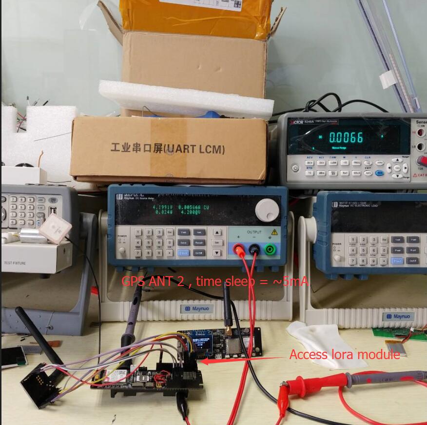
  2. No GPS antenna, no LORA module, sleep current is about 750uA (the ammeter unit in the upper right corner is uA) NANT

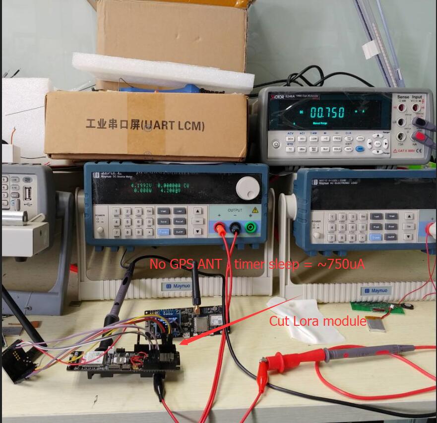
  3. No GPS antenna is used, there is a LORA module, and the sleep current is about 2mA (the unit of the ammeter in the upper right corner is A)

NANT_LORA

Based on this, provide feedback to the LilyGo team as a reference for the next revision

  1. Remove SIM7000 NRESET, release GPIO5, will be used in Lora expansion board
  2. Reset the GPIO Pin to release the HIGH SPEED SPI Pin
  3. GPS active antenna has leakage current during deep sleep, increasing power control, this part of the circuit can be closed when GPS is not used
  4. Add power monitoring IC DIO6809S
  5. ADC power monitoring plus Mos tube control P-FET solution
  6. Use the new pin layout:

1

  1. Add GPIO0 as an external button, you can manually download when the automatic download circuit fails
  2. To reduce external noise, connect a 0.1uF capacitor in parallel with the ADC pin
  3. Change the power supply to PMIC, the specific selection must also consider
ROSW6341 commented 4 years ago

Thanks for the update. I believe several things should be reconsidered. The DIO6809S will hold the processor in RESET mode when it detects low supply voltage, however it is quite possible the current the ESP32 draws in reset is higher than when it is in deep sleep. And while in forced reset, the ESP32 cannot report its condition. Therefore I do not believe the DIO6809S is advantageous to the project. Also I do not believe adding the P-FET control will impact battery usage in any significant way. The two 100K/100K voltage dividers draw a only total of about 40uA. And the P-FET control as depicted in the link has drawbacks having to do with the capacitor in the circuit. And finally the ESP32 ADC are known to be inaccurate. A means to self calibrate them is to add (another) 100K/100K voltage divider between VCC3V3 and ground then feed the mid point to an ADC input. By first measuring it (3.3v / 2) the ADC value can then be used to adjust the other two ADC readings and report accurate values.

lewisxhe commented 4 years ago

The fourth and fifth are suggestions from other users. I just list them here. The design needs to be reconsidered. I also think that adding a reset IC is not a good idea. The current consumption of the P-FET is very small. I think it can be ignored.

Regarding these suggestions, 1,2,3,6,8,9,10 are my personal suggestions @ROSW6341

lewisxhe commented 4 years ago

If PMIC is used, I think ADC detection should be removed

ROSW6341 commented 4 years ago

The P-FET circuit as depicted has a problem when the divider is kept enabled too long. The capacitor will charge up disabling the divider and it cannot be re-enabled until the control signal goes high for a significant enough time to discharge the capacitor. A diode across the capacitor would at least allow for re-enabling the divider more quickly. Adding the circuit would be at the cost of 2 or 4 components to save 40uA of current draw on a design that has a relatively large battery with a solar panel charger. I did not see a control signal in your pin assignments for the GPS antenna power switch. It might be possible to control it via a SIM GPIO pin but I have been unable to determine what state they are in while the SIM is in power down mode. I do not understand how the use of a Power Management IC (PMIC) could invalidate the need for the Analog to Digital Converters.

lewisxhe commented 4 years ago

PIMC is similar to AXP192 and AXP202, but they are not currently used because the SIM800 startup current is too large, leading to PMIC protection. I am conducting another PMIC test, adding soft start to reduce the startup current, and I use SIM800L An upgraded version of SIM800C is used as the test object. If all goes well, the battery test can be removed because the PMIC already has a complete test function. @ROSW6341

ROSW6341 commented 4 years ago

Sorry, one more comment. I realize I come to this project late but I believe adding LORA to the design would result in less optimum results for both NBIoT/LTE Cat-M1 and LORA (cost, complexity, etc). Both are intended for similar purposes and would very likely not be used at the same time or in the same installation. I think splitting the project into two projects would provide better solutions for both. Both would use the ESP32 and basic support circuitry but one would use the SIM7000 while the other would use LORA.

lewisxhe commented 4 years ago

Yes they are not together, lora is just an extension module, i believe few people will let them work together

ROSW6341 commented 4 years ago

OK, now I understand about the PMIC. I has an ADC with multiple inputs eliminating the need to use the ESP32's ADC. I haven't had a chance to check its details but hopefully its adc circuity can accept the voltages from the battery and solar panel without the voltage dividers.

lewisxhe commented 4 years ago

Oh! I even said the wrong topic. The SIM800 mentioned earlier is T-Call. Haha, I will continue to upgrade the SIM7000!

ROSW6341 commented 4 years ago

But if LORA is an extension module the SIM7000 will be there (unused, but adding cost and restricting the use of unavailable ESP pins) when the LORA is needed. I still think two sister designs, one with the SIM7000 and the other with LORA is preferable.

ROSW6341 commented 4 years ago

Obviously the future of this design is not my call. I have a product design in works for which the ESP32 & SIM7000 appear to be ideal and the design you have when I learned of it fit very nicely. I'm making suggestions based upon the assumption the design is to a product board and not a development board. The latter is used to develop a product which when completed, is revised to remove components and features that were needed solely for development.

lewisxhe commented 4 years ago

Ok, thank you for your comments. We will listen carefully! @ROSW6341

kapitan-u commented 4 years ago

In response to:

The DIO6809S will hold the processor in RESET mode when it detects low supply voltage, however it is quite possible the current the ESP32 draws in reset is higher than when it is in deep > sleep. And while in forced reset, the ESP32 cannot report its condition. Therefore I do not believe > the DIO6809S is advantageous to the project.

idea is not holding ESP32 in reset but use DIO6809S as wake up signal source, also it will draw less current that 100k/100k divider

ROSW6341 commented 4 years ago

OK, I understand but what is the ESP32 going to do once it wakes up and realizes the voltage is too low? It might be better off staying in Deep Sleep giving the solar panel time to recharge the battery. Also if the battery voltage is periodically reported in the application's messages, a low battery condition could be recognized and dealt with before it got too low. Every part in an embedded design should justify its cost and the more parts the higher the possibility of some failure mode.

kapitan-u commented 4 years ago

Consider flood sensor application. Battery powered device expected ti sit at the basement for 10 years. Reporting only flood event and weekly status.

lewisxhe commented 4 years ago

If you use DIO6809S as the wake-up source, then I do n’t recommend it. You can use the ulp coprocessor to detect during esp32 deep sleep.

nikil511 commented 4 years ago

But if LORA is an extension module the SIM7000 will be there (unused, but adding cost and restricting the use of unavailable ESP pins) when the LORA is needed. I still think two sister designs, one with the SIM7000 and the other with LORA is preferable.

Hi @ROSW6341 there are many ESP32 + LoRa boards out there, but there are literary zero GSM+LoRA boards. I think having a LoRA addon board on a T-SIM7000 is a very good idea because it enables it to act as a gateway for other LoRa sensors. (Pycom FiPy has LTE + LoRa + Sigfox but no GSM and no GPS, so TSIM7000 wins :-)

@lewisxhe what lora module are using in your design ? The new SX1262 works nicely based on my tests of cubecell and supports all bands. https://heltec.org/project/htcc-ab01/

lewisxhe commented 4 years ago

SX1262 I don't think it is a full frequency band in the true sense. It requires external RC circuits for matching. He can only work well in one frequency band. If other frequency bands are needed, he must be adjusted. What I tested was using sx1276. @nikil511

lewisxhe commented 4 years ago

Hello everyone, I have been testing the LilyGo SIM7000 board for three days, and I feel that the test results are very satisfactory. I set the program to wake up every three minutes, and the buzzer sounded two times when it was started, and four times when it was connected to the network. Then it read the solar voltage and battery voltage and sent it to the server, and then went to sleep. He is still normal now. Work, the battery voltage has been stable at about 3.8V. It is worth noting that in this test, the GPS antenna was not connected, because the power of the GPS antenna is not controlled in this version, and the antenna will lose about 10mA when connected to the antenna. This problem will be quickly resolved. The following is Test Data BAT BOOT There is a problem returned by the solar battery data server, you can see all the data accurately SOLAR These are real-time data full @nikil511 @ROSW6341 @kapitan-u

lewisxhe commented 4 years ago

The test environment is here, There has been no sun in these two days QQ截图20200313150826

nikil511 commented 4 years ago

Yes under normal conditions it works well.

Empty the battery, put a 3w solar or more so you have plenty power, and observe when it shuts off and if it will come back the next day. Using stupid code on purpose (i.e. trying to open gsm modem even if battery is below 3v) in my tests of almost 1 month, the tsim did not wake up half of the days. I believe there is a racing condition bellow 3v and ESP32 boots in a unknown state (maybe download mode) and gets stuck even if power is increased, thus reset needed.

I will try these days with a protected battery and report back. I think that circuit should be added in TSIM and will solve problems.

Another problem to check, especially when its cloudy, is oscillating charge (when battery full or empty) since tp4056 is not really a solar charger.

On Fri, Mar 13, 2020, 09:09 lewis he notifications@github.com wrote:

The test environment is here, There has been no sun in these two days [image: QQ截图20200313150826] https://user-images.githubusercontent.com/22990954/76597919-9aeeb600-653c-11ea-9218-1b1a32c202df.jpg

— You are receiving this because you were mentioned. Reply to this email directly, view it on GitHub https://github.com/Xinyuan-LilyGO/LilyGO-T-SIM7000G/issues/11#issuecomment-598582609, or unsubscribe https://github.com/notifications/unsubscribe-auth/AAHB4OVCJLDJTOIZENFEQELRHHL23ANCNFSM4K5LNVYQ .

lewisxhe commented 4 years ago

I will test the situation you said. I will test it with a dead battery.

lewisxhe commented 4 years ago

I used a 18650 battery with voltage over-discharge to test the SIM7000. The test results were not good. Recently, there was no sun. It was always undercharged. At about zero o'clock at night, it would stop working and the sun rose the next day. Later, it started to work again at about 8 ~ 9 o'clock, so the cycle is, the test result is that when using a battery without power, SIM7000 does not work better. Maybe the solar panel I use is too small, I will try a bigger one BAT SOLAR BOOT

ROSW6341 commented 4 years ago

From the graph it appears the solar panel is only putting out somewhat under 4 volts. That is not sufficient to charge the battery up to 4.2 volts. The minimum voltage input to the TP4056 is 4 volts. If you are not already using one, I would suggest a 6 volt panel. Have you tested the current drawn from the battery when the SIM7000 is shut down and the ESP32 is in deep sleep? How often is the ESP waking up and how long does it run before going back into deep sleep?

nikil511 commented 4 years ago

I have tried multiple solar panels on tsim. The 6v ones will go above 7v when full sun, thus reaching near the limits of tp4056 at 8v. The correct panel to use is 5v and when cloudy it will not charge much and probably will oscillate which is also a problem but at least it will not burn the chip. (Hopefully)

I think tp4056 is ok, but cn3065 is better suited for this application at similar cost. I have been using cn3065 with tcall for almost a year with 2w and 3w solar without problems.

On Tue, Mar 17, 2020, 16:18 Bill Knight notifications@github.com wrote:

From the graph it appears the solar panel is only putting out somewhat under 4 volts. That is not sufficient to charge the battery up to 4.2 volts. The minimum voltage input to the TP4056 is 4 volts. If you are not already using one, I would suggest a 6 volt panel. Have you tested the current drawn from the battery when the SIM7000 is shut down and the ESP32 is in deep sleep? How often is the ESP waking up and how long does it run before going back into deep sleep?

— You are receiving this because you were mentioned. Reply to this email directly, view it on GitHub https://github.com/Xinyuan-LilyGO/LilyGO-T-SIM7000G/issues/11#issuecomment-600096418, or unsubscribe https://github.com/notifications/unsubscribe-auth/AAHB4OW2GW3YWCE64VAMJ5LRH6BCPANCNFSM4K5LNVYQ .

ROSW6341 commented 4 years ago

The CN3065 provides the benefit of reducing the charge current so the input is not as loaded and the output voltage can reach 4.2 volts. The only draw-back I saw was it has a maximum input voltage of 6 volts. There might be a means of using higher voltage panels if the input to the CN3065 was through a LDO regulator. Anyway just a thought. Not sure if it is of any benefit.

ROSW6341 commented 4 years ago

I just went back through the schematic and there appears to be a 6.8v zener diode (D3 at 3D on page 5) shunting the solar input. If that is (still) the case, a 6 volt solar panel should not be a problem.

ro85ac commented 4 years ago

I just went back through the schematic and there appears to be a 6.8v zener diode (D3 at 3D on page 5) shunting the solar input. If that is (still) the case, a 6 volt solar panel should not be a problem.

@ROSW6341 How much power should have the 6V solar panel: 1W, 3W or 6W? I am using a 6V 1W solar panel, but the battery dies after 2 days (sending data through WiFi every 15 seconds). During the day the battery loses around 200mV, but during the night drops to 2500mV and dies.

I am using this one 6V 1W: https://www.aliexpress.com/item/32989724956.html

ROSW6341 commented 4 years ago

Sending data every 15 seconds could be the problem. The ESP32 itself consumes a fair amount of power and could deplete the battery fairly quickly if it runs continuously. Try running it from USB only (no battery) and using a USB power monitor to get an idea of how much current it draws during a 15 second interval. Then use that value to calculate how long the battery should hold up. A typical 18650 battery has a capacity of about 2000 mAh. Divide that by the current value you measured to get the expected life. For example if the current you measured during the 15 second interval averaged 100mA then 2000/100 gives 20 hrs (for a fully charged battery).

ro85ac commented 4 years ago

d could deplete the battery fair

@ROSW6341 I understand. But using a solar panel with 6W than 1W should charge the battery 6 times faster and during the day should recharge it fully. What do you think: a 6V solar panel with 6W power should do the trick?

ROSW6341 commented 4 years ago

The issue will be recharging the battery when there is little or no sunlight and keeping the power consumed to a minimum. An option to consider is to 1) lengthen the time between readings, 2) store multiple readings locally (possibly RTC RAM) 3) only powering up the WiFi to send the saved readings. All-the-while keeping power consumed to a minimum when awake (slower clock speed), light-sleep for delays and staying in DeepSleep between readings.

lewisxhe commented 4 years ago

About the latest version, the test has been completed, and the final test sleep is about 300uA. 2

ROSW6341 commented 4 years ago

Looks good (that's the good news). Now the no-so-good news. I've been developing a low power monitoring system based upon the previous version of the board and have come across a problem. In some instants the SIM fails to power off and it is not possible to detect it when that happens. The power down code I have first shuts down all services, connections, etc then issues the software power off command. If there is not a proper response it retries several times after which it tries to power off using the power key. By monitoring the current I have seen there have been occasions where even then the SIM fails to power off. It might be helpful if the STATUS pin 66 could be monitored by the ESP as it is the documented means to determine if the SIM is truly powered off. I haven't tried it yet but keeping the ability to control the SIM reset pin might be of use even though the documentation indicates it is of no use if the module is powered off.

nikil511 commented 4 years ago

We have also seen this weird behavior with power of sim7000 but I assumed it was a bug in our code as we have played with sleep modes and sim7000 has somekind of persistance with the settings.

In our product design around tsim we are utilizing all available pins (!) So in case this suggestion does make it to next version.... Lewis use a (new) pin that is not exposed in the board or at least an input only pin.

(Btw, Bill, I have the schematic of next version if you are interested)

On Sat, May 16, 2020, 19:35 Bill Knight notifications@github.com wrote:

Looks good (that's the good news). Now the no-so-good news. I've been developing a low power monitoring system based upon the previous version of the board and have come across a problem. In some instants the SIM fails to power off and it is not possible to detect it when that happens. The power down code I have first shuts down all services, connections, etc then issues the software power off command. If there is not a proper response it retries several times after which it tries to power off using the power key. By monitoring the current I have seen there have been occasions where even then the SIM fails to power off. It might be helpful if the STATUS pin 66 could be monitored by the ESP as it is the documented means to determine if the SIM is truly powered off. I haven't tried it yet but keeping the ability to control the SIM reset pin might be of use even though the documentation indicates it is of no use if the module is powered off.

— You are receiving this because you were mentioned. Reply to this email directly, view it on GitHub https://github.com/Xinyuan-LilyGO/LilyGO-T-SIM7000G/issues/11#issuecomment-629672022, or unsubscribe https://github.com/notifications/unsubscribe-auth/AAHB4OTTSMY5R45IBECHEJTRR26EBANCNFSM4K5LNVYQ .

kapitan-u commented 4 years ago

I agree, connecting STATUS pin 66 will be very beneficial.

ROSW6341 commented 4 years ago

Yes, I am interested in seeing the schematic of the next version.

nikil511 commented 4 years ago

@kapitan-u @ROSW6341 Status pin is useful but keep in mind you still have to wait ~5sec or more for the sim7000 to boot in order to confirm status. There should be a better way to determine the status.

@lewisxhe In reference to the new version, schematic v1.6 (May 4) You are exposing input only pins (35/36) that are internally connected to bat & solar dividers. There is no need to expose these pins, nobody will use them.

I think a better idea is to keep 35/36 on battery/solar, put 34 on SIM7000 status, but keep them all internal to the board, and expose pins 16/17 (that were previously not connected) on the board pins so we can have 2 extra GPIOs.

Link to latest schematic v1.6 May 4

ROSW6341 commented 4 years ago

I generally have not had a problem with getting the SIM to power up. Power down has been the problem. On occasion it does not acknowledge the receipt of the command leaving only the PWR KEY. I've monitored the board current via a device in series with the USB and have seen the attempt fail (the current stayed in the 70mA range). Being able to monitor the STATUS pin would allow the code to take additional steps to power off the SIM.

ROSW6341 commented 4 years ago

I've had the opportunity to study the schematic a bit and found a couple of things that might not be quite right. First the CN3065 (U13) has an operating range up to 6v with an absolute max of 6.5v. The zener diode D3 that protects it from over-voltage from the solar input is currently a 6.8v zener (WC). It should probably be changed to a 5.6v zener (WA) which has an upper tolerance limit of 6v. Second, U16 the VBUS-VCC4.2V step down converter is shown with a part number of JW52222. I believe the part number should be JW5222. The board looks like it will be a good development platform, especially with all the LEDs. I'd like to request if possible, that all LEDs that cannot be controlled via code (STATUS, CHRG, STDBY) have cut-jumpers placed in series somewhere so they can be optionally disabled for product deployment by cutting the jumper. NETLIGHT is OK because it can be controlled via code. I understand if this cannot be done because of board size constraints or other reasons but thought I'd ask just-in-case.

lewisxhe commented 4 years ago

The new version is already in production, and the changes will not be implemented temporarily. But another PCI-E version will leave the state to connect to ESP32

domojega commented 4 years ago

Hi to all! I am newbie here so apologize if I say/write something dumb or uncl3ar, but would like to add my 1 cent here. Putting an accelerator/gyro MEMS in the board would be quite useful, adding the possibility to sense movement/theft/earthquake/ whatever...

kapitan-u commented 4 years ago

Agree 100% having MPU9250 would be great. However there must be an option to have it powered while ESP is in deep sleep, so MPU may wake it up on motion.

lewisxhe commented 4 years ago

Adding an IMU to the board will undoubtedly increase the cost, and not everyone needs it, you can use an external module to add it directly

domojega commented 4 years ago

I agree that the price matters but at least, when I do the redevelopment, I try to include all relevant and possible scenarios on the PCB so, putting the placeholder on the PCB is a quite good and cheap option. If anyone wants to have a MEMS on its board, let them just solder one. Adding modules and increase the volume of the device is rather unpopular for me... I would rather see the board with the 18650 as an optionl (if you want it, then buy and solder it) and would just place a connector for the LiPo... Also, software support with examples is miserable and you should provide more instructions on howto basis. But, anyway, the module itself is bullseye.

ROSW6341 commented 4 years ago

Two questions: 1) Will the existing version still be available or will it be replaced by the new version? 2) Any idea when the new version will be available for beta testing and/or sale?

nikil511 commented 4 years ago

Got the new ones today, so they must have more. Check their AliExpress page (or contact lilygo directly)

On Thu, May 28, 2020, 20:45 Bill Knight notifications@github.com wrote:

Two questions: 1) Will the existing version still be available or will it be replaced by the new version? 2) Any idea when the new version will be available for beta testing and/or sale?

— You are receiving this because you were mentioned. Reply to this email directly, view it on GitHub https://github.com/Xinyuan-LilyGO/LilyGO-T-SIM7000G/issues/11#issuecomment-635497232, or unsubscribe https://github.com/notifications/unsubscribe-auth/AAHB4OUMNGSRZQHDZK37XMDRT2PJ7ANCNFSM4K5LNVYQ .

ROSW6341 commented 4 years ago

Thanks for the info. Just order 3. Hope these get here faster than the last version 1 boards.

ClemensGruber commented 4 years ago

I'd like to request if possible, that all LEDs that cannot be controlled via code (STATUS, CHRG, STDBY) have cut-jumpers placed in series somewhere so they can be optionally disabled for product deployment by cutting the jumper.

This is really important! Thanks to point this out @ROSW6341! It makes no sense to optimize power consumption at different areas and burn power with "stupid" LEDs. This may be helpful for debugging but is useless in a low power szenario. Please have this low power setting always in minde when developing a solar and GSM/LTE board!