 CRImier
commented
7 years ago
CRImier
commented
7 years ago Addition - it's very important that 3D model source files are present, due to the fact that KiCad will be moving away from VRML in the future.
Open CRImier opened 7 years ago
CRImier
commented
7 years ago Addition - it's very important that 3D model source files are present, due to the fact that KiCad will be moving away from VRML in the future.
CRImier
commented
7 years ago Components that are the most necessary for case creation:
Front board:
Back board:
Keypad board:
Will be adding component dimensions here over the course of this week, for Chinese breakouts and components without part numbers.
 dwaq
commented
7 years ago
dwaq
commented
7 years ago In regards to ESP-12, are you using the 22 pin version or the 20 pin version? The 20 pin version uses pins 2-21.
Edit: I see your note on the sch about using the 20 pin version. I might need to modify that to be compatible with the 3D model.
CRImier
commented
7 years ago @dwaq AFAIK the 3D model doesn't use the pins for model alignment on the board, instead, it uses the grid reference point, so there should be no problems =)
If the schematic didn't make it clear (I'll re-check), I'm actually using the 22-pin model of ESP-12, but some pins are removed from the ESP-12 footprint, since they're not used anyway and there's more space for routing traces and antenna keepout polygon. If the 3D model has pins that just won't be on the pads, I imagine it's not going to be an issue - this is what it looks like in reality, on a real ZeroPhone =)
dwaq
commented
7 years ago I'm working on the Microphone: W3 now. What are the dimensions? I don't see details on that page and can't tell if 6mm and 5mm is height and radius or what. I can't even make sense out of it while looking at the footprint on the PCB.
PS, you can use the task list markdown for the models remaining and add a check when they're done instead of crossing out. But that's personal preference I guess.
CRImier
commented
7 years ago Found the 2-pin switch 3D model here
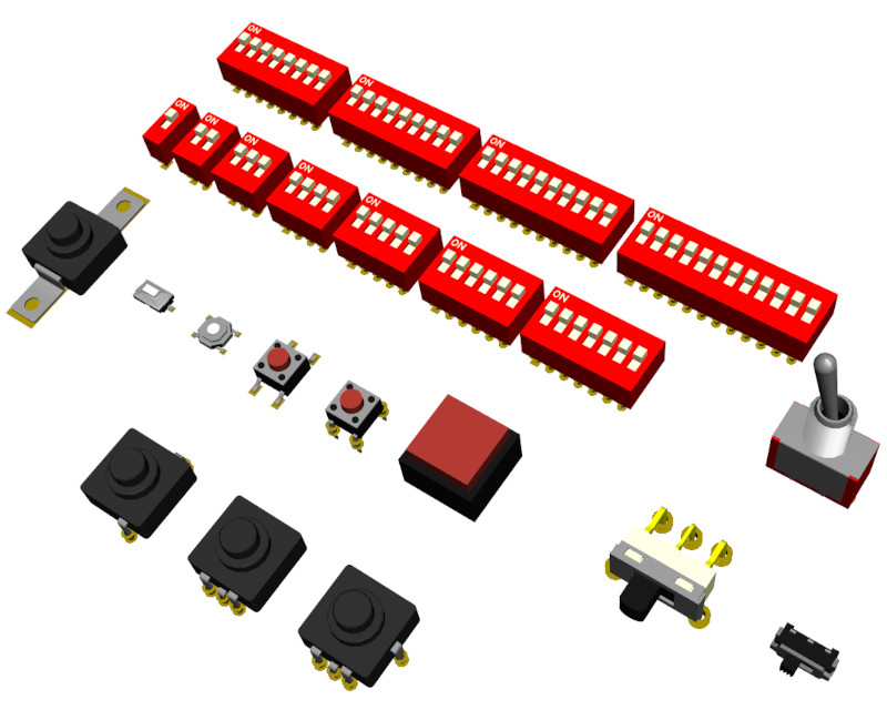 2-pin SMD button on the left to the SKQG button
CRImier
commented
7 years ago Task list - done, thank you for suggestion!
CRImier
commented
7 years ago Microphone: can't measure it right now but will do in 2 hours. I think 6mm is height and 5mm is width.
dwaq
commented
7 years ago As for the OLED display, I found Monochrome 1.3" 128x64 OLED graphic display on Adafruit which appears to be compatible with your design, but not the exact model that you're using. It provides dimensions but not a 3D model so I'd have to design it. Should I use these dimensions or can you find the dimensions of the display you're using? For case design, I assume screen dimensions are going to be very important, so this model needs to be correct.
CRImier
commented
7 years ago @dwaq - you're right about screen dimensions being very important. I can't measure my screen right now, and can't check if the dimensions are right, either, but I'll measure the screens I'm using and post the dimensions today or tomorrow.
CRImier
commented
7 years ago @dwaq Just measured the microphone, it's 5mm in width and 6mm in height.
dwaq
commented
7 years ago I tried modeling those dimensions today and it didn't look right. Can you provide a photo of the part soldered to the board so I can see how it's supposed to look? Thanks.
CRImier
commented
7 years ago @dwaq Here it is:
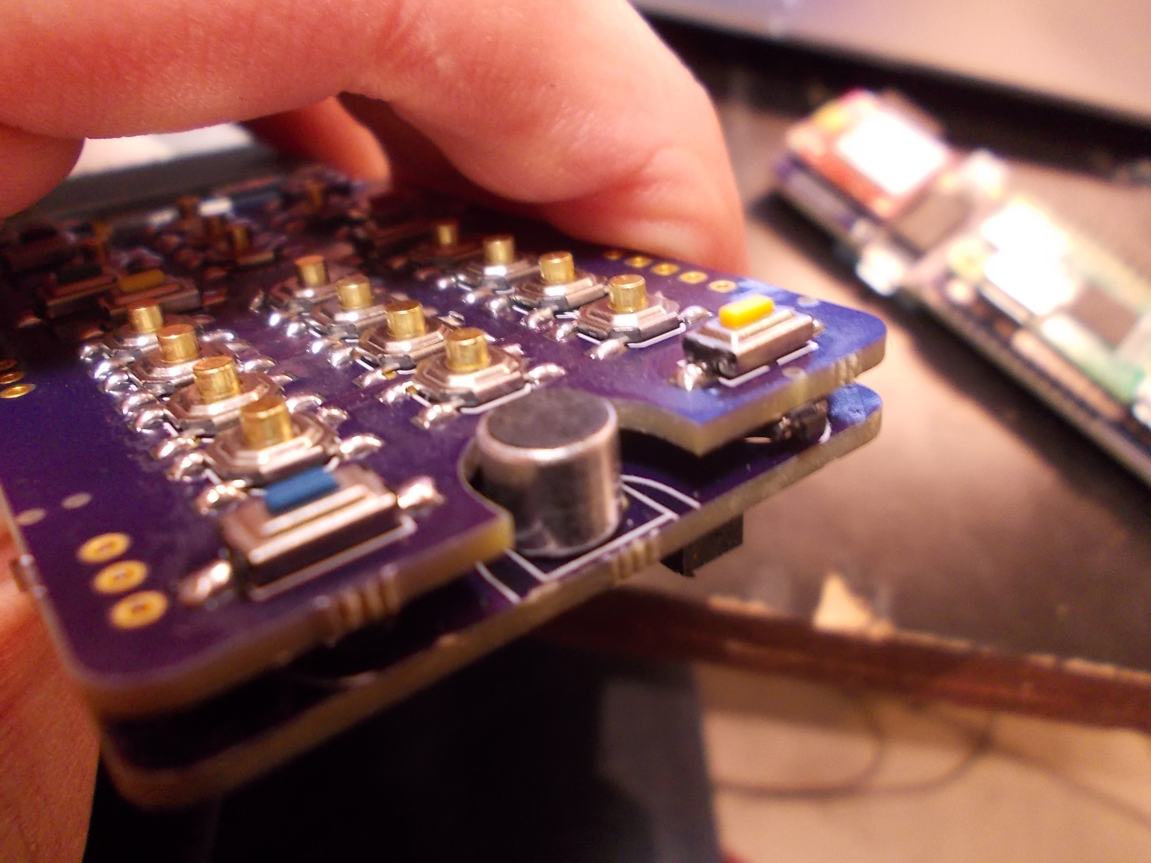 It's not the part I'm using on beta prototype there are photos of, but it's one of the samples I bought from TaoBao in QTY30 that was the best of them all, microphones like one currently on beta prototype would be great to use as they're smaller, but the sellers I used didn't have any of those.
CRImier
commented
7 years ago Pushed new changes - changed the crystal footprint to a reasonable one and removed pin headers that aren't actually soldered on.
dwaq
commented
7 years ago Here's a capture of the microphone modeled at 5mm width, 6mm height. As you can see, it doesn't fill out the terminal block silkscreen like the component in your photo does. It also barely covers the holes.
 I'll make a pull request regardless and you can either let me know what to change, or modify it yourself.
CRImier
commented
7 years ago Hi! It should be OK, mostly it's the center position and height of microphone that matters . I'll check its height once I'll think of a way to do that. As for the possible modifications - it would be good to have a thin black layer on the top, just like it is with microphones I'm using - but nothing more, you could just paint the top black.
CRImier
commented
7 years ago @dwaq - sorry for the screen dimension delay. Screen dimensions added in #24 (so that this issue isn't picture-heavy).
CRImier
commented
7 years ago Added #25 for TP4056 charger breakout board
CRImier
commented
7 years ago Fixed pin headers on back board, chaned pushed to repo
dwaq
commented
7 years ago For RGB LED: D3 (5050 package), are these dimensions correct for the part you're using? Especially the location of the polarity mark? I found a few 3D models of 5050 LEDs but they don't match these dimensions. If I have to model it myself, it's just going to be a cube -- I can't make it as detailed as the 3D models out there.
CRImier
commented
7 years ago @dwaq Yes, that's the correct type. As for the dimensions - could this just be a scaling issue?
dwaq
commented
7 years ago This one has the wrong dimensions (CREE must do it differently) - EDIT: I guess I could take this and scale each direction to make it fit. I can do this if I don't hear from the guy in the 3rd line This one has the polarity mark on the wrong location I found this one and converted the file format and it appears ok, but I need to get permission from him to use it
CRImier
commented
7 years ago The first one: yeah, if it could be scaled, it would be very cool. The third one is OK too - it's a 4-pin one (instead of 6 pins), but it's not too much of a problem since this model is meant to be a guide for where to make a cutout/light path in the case, not to be 100% pin-perfect.
dwaq
commented
7 years ago All that's left is the modules.. These are too complicated to create using my current design flow. I don't know the "correct" way to make these. Create them in KiCad and export the 3D model? Create them from the ground up in some 3D cad system? If you know of a tutorial on how this is typically done, I might be able to try it. Otherwise, I'm going to leave these items for someone else to tackle.
CRImier
commented
7 years ago You know, making the parts as KiCad PCBs and them exporting them does make a lot of sense, I could easily do that. For example, the current GSM module is basically a PCB with a GSM module, SIM slot and pin headers. I could easily model that, and then it could be exported to VRML and imported to another board. It's still going to need some simpler blocks, like the SIM holder, the GSM modem itself (basically a flat square block) and an inductor - would you be interested in drawing those from dimensions? That'd finish the 3D modelling stage, so we could start designing cases =)
CRImier
commented
7 years ago Also, @dwaq - could you find a 3D model of a Pi Zero? The model needs to have USB&HDMI connectors and an empty GPIO header (with holes, preferably), but that's pretty much the only hard requirement.
dwaq
commented
7 years ago As far as the module comment.. Yeah, I think I can help make some components. It might be nice to make them in a separate repo so that others can more easily find them and use them and we can just import the product of that work into this model.
CRImier
commented
7 years ago 
KiCad provides board 3D view/export functionality, which would be very useful for creating ZeroPhone cases. However, for many components used by ZeroPhone there just aren't suitable 3D models. What's necessary is to find/develop simple to-scale 3D models for these components and link them to the PCB so that they appear in the 3D viewer, and can then be exported by the KiCad VRML export option for case building. Most of the component size data can be gotten from footprints and ZeroPhone photos, and I'll post more component photos shortly for those components where dimensions might be unclear.