Closed radiomanoff closed 2 years ago
Thanks a lot for the feedback, I'm happy you found this useful! :)
I originally intended the ESS_MUTE_FET pin to be able to mute the DAC if there was any popping when switching inputs or when powering on. Since that didn't happen it's unused and you can leave it disconnected and skip the FET.
You might want to keep R4 and C11 (100kR to VCC / 2.2uF to GND) on the mute pin as they act as a soft-start for any power-on pops. The FET was there as the DAC runs off of 3.6V as opposed to the 3.3V of the Pico.
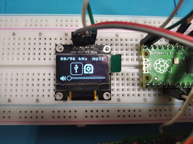
Hello. When connecting via USB, extraneous sound is heard. Maybe use the ESS_MUTE_FET pin, turn it on at the beginning of the RPI-PICO periphery initialization, and turn it off after the end of the transition processes? Also interesting pin TPA6130 - SD(shutdown), it can also be used in the project... I hope you don't mind that I changed the code a bit. Since I use WM8804, there is an idea (probably somewhat wrong) to use a relay for switching: external TOSLINK or SPDIF RPI-PICO. Use a free RPI-PICO pin to switch. Here is a rough diagram:
And make the menu look like this:
Hey!
You can definitely use the mute pin if you want to get rid of power-on pops with software instead of the RC network, you'll just need to have a pulldown to make sure it doesn't pop while the pico is still booting and set it high a few hundred milliseconds later. For reference the 2.2u/100k network on the schematics gives you ~220ms of delay.
On the TPA6130 you can send a shutdown over I2C (Bit0 on register 1) and save yourself a pin if you want to shut it down :) You shouldn't get any pops out of the headphone output as the chip starts up with both channels muted though (and I don't hear any on my boards).
I did notice you're tapping off your line out after the DC coupling caps, but you don't have to do this as the ESS9023 has a line-level opamp driver. They're there for the TPA6130 when in single-ended mode (section 9.2.2.1 in the datasheet) and should ideally be close to it.
I don't see why you wouldn't be able to use a relay to switch SPDIF, the bandwidth isn't that high and it should work just fine! Make sure to get a 3v3 compatible TOSLINK receiver (i.e. TORX147 instead of TORX179) if you're using optical inputs.
Please feel free to modify the code as you need, looks great with two inputs :) Are you planning on building this inside a box?
Please stay safe! I hope peace returns soon, nobody deserves to ever endure what's happening right now. We all stand with Ukraine 🇺🇦
Not yet implemented TPA6130
Hello. Tell me, I can't understand in which file the pin of the SPDIF OUT is assigned? When I compile an example from the sine_wave pico_playground, with a SPDIF output, the pin for the SPDIF OUT is changed in the file ../pico/sine_wave/pico-extras/src/rp2_common/pico_audio_spdif/include/pico/audio_spdif.h
Sorry for the slow response, the SPDIF pin is assigned here: https://github.com/alexstanoev/FoxDAC/blob/master/firmware/foxdac/CMakeLists.txt#L27
Putting the front panel on a vertical board is a good idea, looks great!
Thank you very much. I just started learning сmake, so some things are not clear to me. Here are a few more photos, TPA6130 and toslink input has not yet been implemented
USB can also be connected with wires to the back wall, there are pads for soldering wires from the bottom of the Pico
Free space for toslink input and relay
On the right is a free space under the TPA6130
Thanks for an interesting project. Sounds good in my opinion. I changed the project a bit and used WM8804 (it will work by default too, you just need to switch to 1 TOSLINK). The device works like a USB Sound Card. The question is, how is the ESS_MUTE_FET pin connected to the MUTE pin of the ESS9023 DAC used?