 almindor
commented
1 year ago
almindor
commented
1 year ago Hmm, as a quick check can you try doing DisplayOptions::default() and lcd.clear(Rgb565::GREEN) or such just to see if the basics work?
Closed mutantbob closed 5 months ago
almindor
commented
1 year ago Hmm, as a quick check can you try doing DisplayOptions::default() and lcd.clear(Rgb565::GREEN) or such just to see if the basics work?
 mutantbob
commented
1 year ago
mutantbob
commented
1 year ago Using DisplayOptions::default() and let c3 = Rgb565::new(0, 0x3f, 0x1f); lcd.clear(c3); still results in a black screen
almindor
commented
1 year ago Using
DisplayOptions::default()andlet c3 = Rgb565::new(0, 0x3f, 0x1f); lcd.clear(c3);still results in a black screen
Hmm that sounds like a bug. I have an old st7789 but didn't use it for ages since I'd have to rewire my setup from the other display so I won't be able to check this out right now.
I'm labeling this as a bug for now. Do you have a logical analyzer per chance? We could try to see if the data sent out differ and where. I'm guessing you didn't touch the SPI setup in any way when switching the driver?
mutantbob
commented
1 year ago I did not change the SPI when switching the driver. My source code is at https://github.com/mutantbob/lcd-esp32 . I compile it using (. ~/vendor/rust-build/export-esp-rust.sh ; time cargo build --features mipidsi)
almindor
commented
1 year ago And just to make sure we're not stalling anywhere, the code execution reaches the "end" right? As in we're not stuck somewhere in display::init or such.
mutantbob
commented
1 year ago Correct, println!("beep") and boop are both showing up in espmonitor, and the neopixel is rotating through the rainbow.
almindor
commented
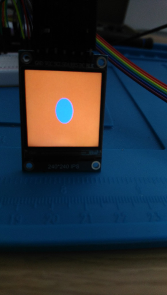
1 year ago I'm not sure what's wrong o.O my display works/
Picture:
Full code:
#![no_std]
#![no_main]

extern crate panic_halt;

use display_interface::WriteOnlyDataCommand;
use display_interface_spi::SPIInterfaceNoCS;
use e310x_hal::delay::Delay;
use e310x_hal::spi::Spi;
use embedded_graphics::draw_target::DrawTarget;
use embedded_graphics::pixelcolor::*;
use embedded_graphics::prelude::{OriginDimensions, RgbColor, Size};
use embedded_hal::digital::v2::OutputPin;
use embedded_hal::spi::*;
use hifive1::pin;
use hifive1::{
    hal::{prelude::*, DeviceResources},
    *,
};
use mipidsi::{models::*, ColorOrder};
use mipidsi::{Display, DisplayOptions};
use riscv_rt::entry;

type DisplayRgb = Rgb565;
type DisplayModel = ST7789;

#[entry]
fn main() -> ! {
    let dr = DeviceResources::take().unwrap();
    let p = dr.peripherals;
    let pins = dr.pins;

    // Configure clocks
    let clocks = hifive1::clock::configure(p.PRCI, p.AONCLK, 320.mhz().into());
    let mut delay = Delay::new();

    hifive1::stdout::configure(
        p.UART0,
        pin!(pins, uart0_tx),
        pin!(pins, uart0_rx),
        115_200.bps(),
        clocks,
    );

    sprintln!("Init");

    let mut cs2 = pin!(pins, spi0_ss2).into_output();
    // main spi pins
    let sck = pin!(pins, spi0_sck).into_iof0(); // dig13
    let mosi = pin!(pins, spi0_mosi).into_iof0(); // dig11
                                                  // display helpers
    let mut cs0 = pin!(pins, spi0_ss0).into_output(); // dig10
    let dc = pin!(pins, dig9).into_output(); // dig 9
    let rst_display = pin!(pins, dig8).into_output(); // dig8

    // ensure other devices are off
    cs0.set_high().unwrap();
    cs2.set_high().unwrap();

    // Configure SPI
    let pins = (mosi, (), sck);
    let spi_display = Spi::new(p.QSPI1, pins, MODE_3, 40.mhz().into(), clocks);
    sprintln!("SPI done");

    let di = SPIInterfaceNoCS::new(spi_display, dc);

    let mut display = Display::with_model(di, Some(rst_display), DisplayModel::new());
    sprintln!("Driver created [new]");

    display
        .init(
            &mut delay,
            DisplayOptions {
                color_order: ColorOrder::Bgr,
                ..Default::default()
            },
        )
        .unwrap();
    sprintln!("Display init done [new]");

    display.clear(DisplayRgb::BLACK).unwrap();
    sprintln!("Display clear done [new]");

    sprintln!("Main draw");
    lcd_test_pattern(
        &mut display,
        DisplayRgb::new(0x01, 0x10, 0xFF),
        DisplayRgb::new(0xFF, 0x10, 0x01),
    )
    .unwrap();

    loop {
        continue;
    }
}

pub fn lcd_test_pattern<DI, RST, M, C: RgbColor, PinE>(
    lcd: &mut Display<DI, RST, M>,
    c1: C,
    c2: C,
) -> Result<(), mipidsi::Error<PinE>>
where
    DI: WriteOnlyDataCommand,
    RST: OutputPin<Error = PinE>,
    M: Model<ColorFormat = C>,
{
    let Size { width, height } = lcd.size();
    let pattern = (0..height as i32).flat_map(|y| {
        (0..width as i32).map(move |x| {
            let dx = x - width as i32 / 2;
            let dy = y - height as i32 / 2;
            if dx * dx * 2 + dy * dy < 40 * 40 {
                c1
            } else {
                c2
            }
        })
    });
    lcd.set_pixels(0, 0, width as u16, height as u16, pattern)
}I did Bgr instead of Rgb here in DisplayOptions by accident (from another display's code before) but that only changes the colors.
mutantbob
commented
1 year ago It might be a corner case specific to the ESP32. or ESP32 Pico Mini 02.
mutantbob
commented
1 year ago Also, it looks like you are using MODE_3, while I was using the default (MODE_0 = IdleLow, CaptureOnFirstTransition ?)
almindor
commented
1 year ago Also, it looks like you are using
MODE_3, while I was using the default (MODE_0=IdleLow,CaptureOnFirstTransition?)
Yes, MODE_0 is technically correct... but only if the CS pin is actually used. In the cheapo ST7789 (such as mine) where they hardwired the CS to GND it causes a clock timing issue and MODE_3 works.
See https://github.com/Bodmer/TFT_eSPI/issues/1758#issuecomment-1091546681 and https://www.instructables.com/Adding-CS-Pin-to-13-LCD/
Try switching to MODE_3 to see if it works. I wonder if it's just a timing/optimization issue at this point.
almindor
commented
1 year ago @mutantbob did you try MODE_3 yet? I'm really curious what the issue here is.
mutantbob
commented
1 year ago I had a chance to try MODE_3 on both an ESP32 and an RP2040. It works. I had to change the ColorOrder to Bgr. I am not sure how that will interact with my OV5642 which seems to be working with MODE_0. I wonder why this changed between the st7789 crate and the mipidsi crate.
It also appears that mipidsi::models::st7789::ST7789::display_size() returns 240x240, which is not what I expected. Maybe that is its own issue.
almindor
commented
1 year ago I had a chance to try MODE_3 on both an ESP32 and an RP2040. It works.
Yes, the MODE_3 is basically a design issue with how they handled the CS to ground, it has to do with the 1st clock signal AFAIU.
I'm getting waveshare ST7789 displays with proper CS pins so I'll be able to test if they work fine in MODE_0 (and possibly emulate the MODE_3 with grounded CS).
I had to change the ColorOrder to Bgr. I am not sure how that will interact with my OV5642 which seems to be working with MODE_0.
The Bgr is probably because I did a MADCTL xor for the BGR bit for St7789 model in MIPIDSI. I just noticed my display was the other way around and assumed it was a chip bug. I think it might actually have to do with that clock/cs signal problem tho. I'll probably remove that bit override.
I wonder why this changed between the st7789 crate and the mipidsi crate.
I think it's an optimization/timing thing. One of the two implementations is probably somehow slightly slower making it react different due to that 1st clock signal issue on the display. Not sure.
Code wise they're nearly identical. The only difference is that
It also appears that mipidsi::models::st7789::ST7789::display_size() returns 240x240, which is not what I expected. Maybe that is its own issue.
Yes that's separate. I consider ST7789 to be 240x240 (with framebuffer size 240x320), while others like ST7789V can have different display sizes. What size does your have (visible and framebuffer)?
mutantbob
commented
1 year ago I have the Adafruit 2.0" ST7789 : 320x240
almindor
commented
1 year ago @mutantbob could you re-check with v0.2.2 please? I think #24 should've fixed these issues as well.
 andreban
commented
1 year ago
andreban
commented
1 year ago Just ran into the black screen - I can confirm switching from MODE_0 to MODE_3 fixes it.
I also tested the fix for the colours (even though I didn't initially run into it, since I'm using v0.30. I can repro on v0.2.1 and can confirm it's fixed on v0.2.2 and onwards.
almindor
commented
5 months ago Closing as fixed, re-open if it still occurs
 rfuest
commented
5 months ago
rfuest
commented
5 months ago I did just run into the same issue, where a ST7789 based display without CS wouldn't work in MODE_0 but did work MODE_3. I think this issue should be included in the troubleshooting doc and/or the API docs.
I had the following code working on the Adafruit ESP32 Feather V2 (ESP32-PICO-MINI-02) with the st7789 0.6.1 crate
I converted it to
but the screen goes black and stays black. What have I overlooked?