 angelpereyra
commented
6 years ago
angelpereyra
commented
6 years ago Hi all, which is the configuration needed on the Arduino IDE? ESP8285, 74880 baud,... ?
Thanks!
Closed Majo96 closed 6 years ago
angelpereyra
commented
6 years ago Hi all, which is the configuration needed on the Arduino IDE? ESP8285, 74880 baud,... ?
Thanks!
 geekypenguin
commented
6 years ago
geekypenguin
commented
6 years ago See the wiki...
 FatBeard
commented
6 years ago
FatBeard
commented
6 years ago Hi guys. Is anyone having problems with the T1 UK 1 gang and 2 gang turning on and off randomly without being pressed. Button 1 on both variants is causing problems. Button 2 seems fine. Something appears to be setting off the capacitive button post Tasmota flash.
 SupraJames
commented
6 years ago
SupraJames
commented
6 years ago I have 4 of these (2 and 3 gang) deployed and have never had that happen with any version of the firmware.
 jeylites
commented
6 years ago FatBeard
commented
6 years ago
jeylites
commented
6 years ago FatBeard
commented
6 years ago Thanks for the response guys. @jeylites Are you saying to flash with the esptool first and then flash tasmota over the air? Also have you had the issue i described or is esptool/tasmota just a way of fixing issues genericall?
jeylites
commented
6 years ago @FatBeard
Yes Flash with ESP Tool as shown below and on the third attempt flash with Tasmota. Out of twenty eight , 3gang T1s that I flashed, only three had an issue like yours. So much so these days any new Sonoff, I clear out the flash before re flashing with Tasmota simply because I do t want to do it twice.
Over the air something I have yet to explore. All my flash has been manual. I got to learn how to do OTA at some point.
Open a command prompt and execute command esptool.py --port COM5 erase_region 0x0F4000 0x008000 Optional Clear the complete flash with command esptool.py --port COM5 erase_flash
jeylites
commented
6 years ago @FatBeard is your UK t1 the latest version or old type. Old type meaning PSF module types...
I have both OLD and NEW, it bothers me that the back Light on the NEWER ones are dimmer than the OLDER one which makes it difficult to see the buttons at night.
Do you have similar issues?
FatBeard
commented
6 years ago @jeylites I seem to have the older ones with the PSF sticker/module. Didn't realise until now that there were different versions of it. See attached below.


jeylites
commented
6 years ago Yeah, that’s the old one. Thinking of it I like the old one better for its bright LED touch :)
I currently looking at way to crank up the brightness of the newer ones. If any one have ideas, post it up...
On Fri, Mar 2, 2018 at 10:57 PM FatBeard notifications@github.com wrote:
@jeylites https://github.com/jeylites I seem to have the older ones with the PSF sticker/module. Didn't realise until now that there were different versions of it. See attached below.
[image: img_0208] https://user-images.githubusercontent.com/4692143/36904794-979549f8-1e29-11e8-9d72-1db3c0b12d8d.jpg [image: img_0206] https://user-images.githubusercontent.com/4692143/36904795-97afee34-1e29-11e8-8962-c4744cc25bba.jpg
— You are receiving this because you were mentioned. Reply to this email directly, view it on GitHub https://github.com/arendst/Sonoff-Tasmota/issues/1424#issuecomment-369942954, or mute the thread https://github.com/notifications/unsubscribe-auth/AIw6wLogEftzWTBp3cP1Lz5RyCJwZ-1hks5taV3NgaJpZM4RLpLp .
-- Sent from Iphone Mobile
 MTrab
commented
6 years ago
MTrab
commented
6 years ago Have any of you tried this version of a T1 EU 2 Gang?
Can't see any holes for the pins to flash the MCU.


jeylites
commented
6 years ago @MTrab You will have to connect to the PSF...
 Herschdorfer
commented
6 years ago
Herschdorfer
commented
6 years ago Can somebody post a picture of the T1 EU 2Gang? I want to reverse engineer the board a bit and want to see the difference in the parts that are actually soldered.
Here are some high res pictures of my T1 3Gang UK


and a T1 1Gang EU


SupraJames
commented
6 years ago I just took pictures of my UK T1 2-gang, but then realised you said EU version. Do you still need the UK plctures?
Herschdorfer
commented
6 years ago I think the parts are the same, evening the labels. Everything is welcome! :)
Thanks!
SupraJames
commented
6 years ago T1 UK 2-gang
Wall part

Note that bent header pins are added by me


 Thoom19
commented
6 years ago
Thoom19
commented
6 years ago I bought couple of EU version switches, glad i could share internals photos :)
1 button version:
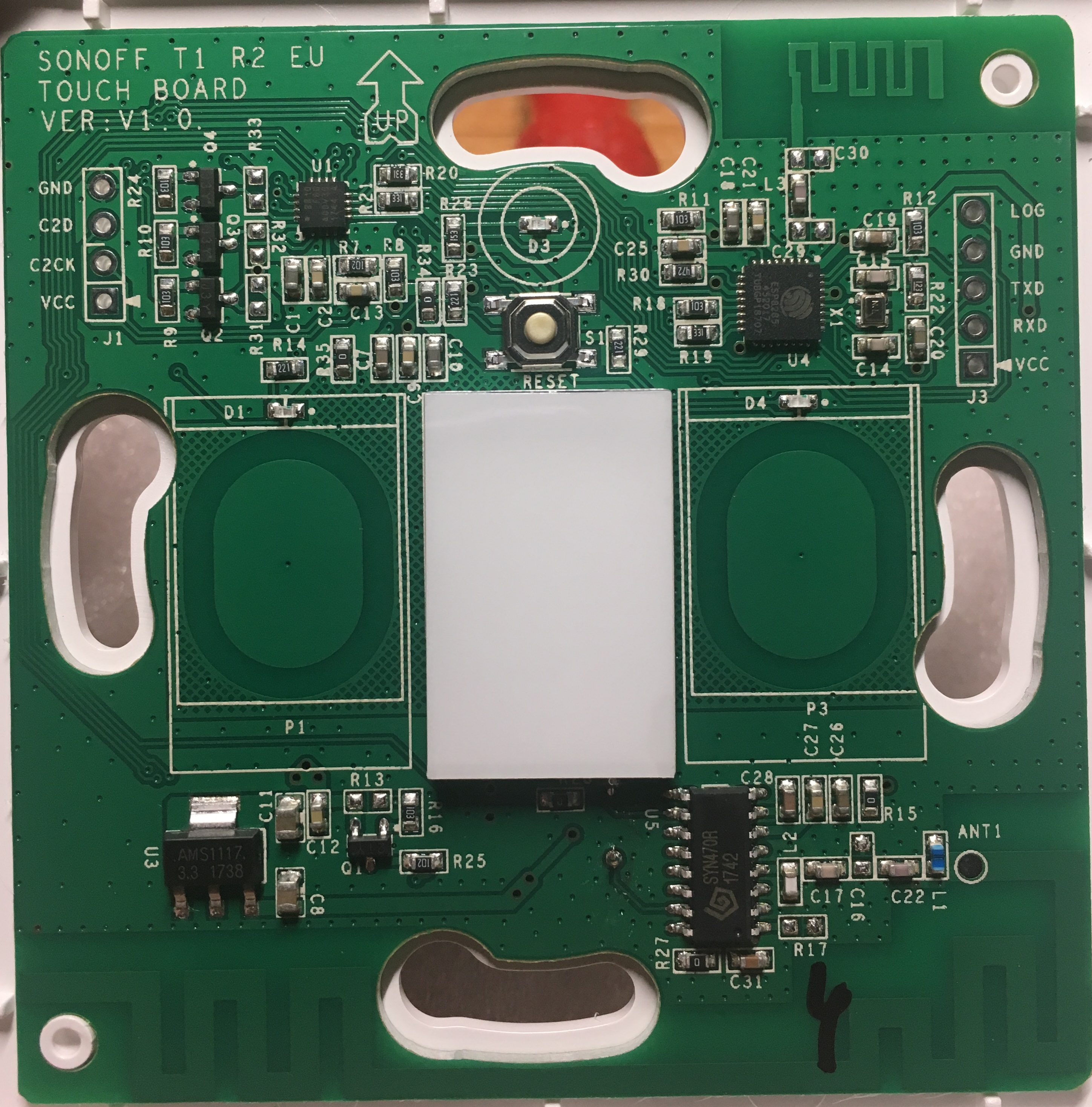

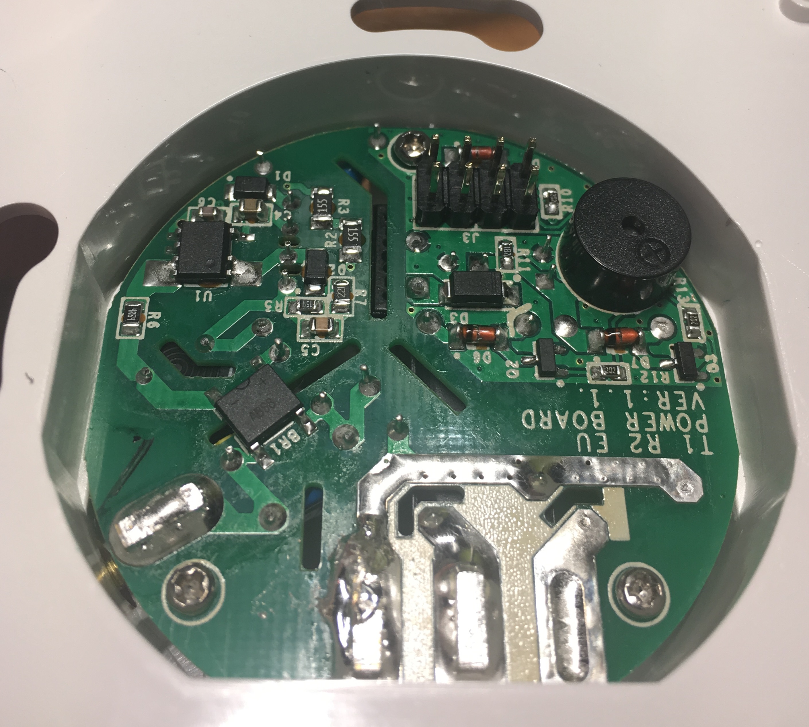
2 button version:


Note that GPIO2 is not available there at J3 connector :(
Herschdorfer
commented
6 years ago merci! :)
My idea was that the buttons are maybe activated in the firmware via resistors and that the actual firmware is the same.
it seems like that the parts are the same for versions. Stange is that C3 is missing in the 1 gang and 2 gang version.
Maybe i will try to read the firmware from the extension chip.
 kanttti
commented
6 years ago
kanttti
commented
6 years ago Just received one Sonoff T1 R2 EU 2-gang and looks just like in @Thoom19 pics. Uploaded Tasmota and after setting SetOption13 ON everything works like a charm.
I also noticed that the 5th pin in J3 connector (with text LOG next to it) IS connected to GPIO2! It can also be seen in pics above if you follow the traces carefully :)
How about in UK model? Is the 5th pin also connected to GPIO2 of ESP8285? If yes, Should the GPIO2 setting be enabled in Tasmota Configuration UI?
 Bolukan
commented
6 years ago
Bolukan
commented
6 years ago You select the 8285 board in the Arduino GUI? Is that really giving another performance compared to selecting the 8266 board in the Arduino GUI? I ask this because I tried both and did not really experienced a difference on first glance. (And if it has consequences, I will update the wiki)
Herschdorfer
commented
6 years ago I am selecting also 8285 in the GUI. so far everything works fine.
 kegra
commented
6 years ago
kegra
commented
6 years ago I got the exact one as Thoom19 sonoff T1 EU 2CH but I cannot flash it, I tried pressing button 1 and then hold reset for few seconds and then release, I can confirm that the central (wifi) led is not blinking or lights up and the two button are dimly lit, but I cannot flash it. the strange thing is that now every time I give power via the ftdi the situation is not changing. I mean that it stays like that and i have no blinking in the wifi.... any help how to flash this correctly? @kanttti @Thoom19
Bolukan
commented
6 years ago @kegra, did you remove it from the backplate with the relay? Your procedure sounds ok to me.
kegra
commented
6 years ago Yes I did that in the first place. but the weird thing is that if i disconnect the ftdi should the sonoff return to the previous state? i mean led in wifi blinking etc? @kanttti
kegra
commented
6 years ago @kantttiI have flashed in the past several sonoffs without any problems. to clarify something button 1 is the one on the left as we look the board with the up arrow pointing up :-) because the wiki shows only the old UK version (not the same as @Thoom19 and yours.)
Bolukan
commented
6 years ago Look to your flash settings? DOUT and that stuff
Bolukan
commented
6 years ago Updated the wiki to include the US-variant, reorder the flash instruction and added a description of the EU layout. Only doubt on whether you should advise people to use the ESP8285 board API and create a specific 8285.bin or whether they can use the ESP8266 - as mentioned in the general instructions.
kanttti
commented
6 years ago @kegra I'm using Visual Studio Code and didn't make any change to the Tasmota code.`Version uploaded was 5.12.0h. In platformio.ini I'm using all defaults
platform = espressif8266
framework = arduino
board = esp01_1m
board_flash_mode = dout
build_flags = -Wl,-Tesp8266.flash.1m0.ld
lib_deps = PubSubClient, NeoPixelBus, IRremoteESP8266, ArduinoJSON
extra_scripts = pio/strip-floats.py
Please note that to enter flashing mode you need to (at least for 2ch model)
After this the Wifi led will NOT be lid and the touch buttons will be lit dimly and you can upload the program.
Does somebody know in T1 1ch model, is it the middle touch plate (the only one) you need to hold to enter flash mode or do you need to short circuit some pins going to the missing leftmost touch plate?
kegra
commented
6 years ago @kanttti , thank you for giving all the details and for spending time trying to help, i have done all exactly as you say , i have now two sonoffs t1 eu 2ch at the exact same state (no wifi lit , buttons dimly lit ) tried both to reverse also trx to trx and trx to rx in case labeling was not the right no luck... Can i revert them to boot normaly ? exit flash mode ? seems that even removing power both return to the same state.
kanttti
commented
6 years ago @kegra Have you tried to clean touch button 1 panel? Maybe you have left residue to the panel and for ESP it seems to be hold down all the time and it enters flash mode on every boot up?
In my T1 there was some minor residue left to the panel that caused the lights to switch on/off every minute. After cleaning the panel with a damp cloth I haven't had any issues. This residue could only be seen as a greasy fingerprint in bright light.
kegra
commented
6 years ago @kanttti I have even removed the thin plastic film that is on top to make sure no residue has been left, also this is happening to two not just one T1 both of them exact same behaviour, entered flash state, and then no matter how many time i remove power and connect power again the T1s remain in the same state.
unable to flash them , unable to go back also , this is very weird behavior.

jeylites
commented
6 years ago @kegra Use ESP tool to clear the flash followed by upload. Check wiki
On Thu, Mar 29, 2018 at 1:42 AM Ioannis notifications@github.com wrote:
I have even removed the thin plastic film that is on top to make sure no residue has been left, also this is happening to two not just one T1 both of them exact same behaviour, entered flash state, and then no matter how many time i remove power and connect power again the T1s remain in the same state. unable to flash them , unable to go back also , this is very weird behavior. [image: img_8767] https://user-images.githubusercontent.com/8533178/38046446-66d4d2ee-32c8-11e8-8872-0999532d0221.JPG
— You are receiving this because you were mentioned. Reply to this email directly, view it on GitHub https://github.com/arendst/Sonoff-Tasmota/issues/1424#issuecomment-376973609, or mute the thread https://github.com/notifications/unsubscribe-auth/AIw6wAw7OibDcOnYf1ZGtR0IZNQUWfi3ks5ti8uGgaJpZM4RLpLp .
-- Sent from Iphone Mobile
kegra
commented
6 years ago @jeylites @kanttti , thank you for the suggestion , esptools same as platformio cannot connect to T1. failed to connect to espressif , seems like the T1 is not in flash mode even thought visualy seems so... but i have no clue how to exit that state i have tried everything...
geekypenguin
commented
6 years ago Have you tried manually jumpering gpio0 to groubd when you power on the sonoff? This is the hard way to enter flashing mode bypassing all the push buttons etc?
What does a serial output of the bootloader (74500 baud) show when you power on the sonoff? If you're not getting an output try reversing tx and rx
kanttti
commented
6 years ago When you power on the board normally (no flashing mode), the GPIO0 should be high (around 3V). Touching the touch panel should pull it low. You should be able to see this transition with a normal multimeter.
3.3V should be found in the via pointed in picture below.
As geekypenguin said. Try to pull down GPIO0 manually from R19 to ground. This way you can pull down first, then connect power.
Is your usb-ttl board still working with other esp boards?

kegra
commented
6 years ago @kanttti thank you for the detailed instructions I will try this, tomorrow because i have no soldering or multimeter here , need to go to a friend for that, my FTDI works perfectly I just flashed a sonoff basic just to make sure that this was not the problem. Its very weird for me that the T1 keeps that state (as in the photo i uploaded during power on /off) also in that state pressing reset just turn off all lights and nothing else happens.
geekypenguin
commented
6 years ago Check them out our.of the bootloader serial console if you can't get the gpio0 method working until tomorrow.that will tell you if there is a problem with the bootloader (likely a dead board) or if it's just a software/flashing problem. If the software is missing or corrupted after a failed flash, then it will boot to bootloader every time regardless, which could explain the symptoms you see
kegra
commented
6 years ago @geekypenguin i connected ground to R19 as @kanttti showed before connecting the usb , connected and nothing changed , T1 at the state i show in the picture few posts above and esptools and platformio cannot upload or erase the flash , same exact ftdi usb pc platfrom that few minutes ago flashed a sonoff basic. out of options and luck , with two "bricked T1" i have a 3rd but really i am afraid i will turn that to a zombie too....
geekypenguin
commented
6 years ago Ok, it's very unlikely that you have bricked them completely. What does the serial console show when you connect the ftdi? If the symptoms don't change when connecting gpio0 to ground then it's deffinatley not booting to flash and is stuck at the bootloader, but without seeing the serial console I can't say what state the bootloader is in
kegra
commented
6 years ago @geekypenguin i get this when i give power to t1
Exception in thread rx: Traceback (most recent call last): File "/System/Library/Frameworks/Python.framework/Versions/2.7/lib/python2.7/threading.py", line 810, in __bootstrap_inner self.run() File "/System/Library/Frameworks/Python.framework/Versions/2.7/lib/python2.7/threading.py", line 763, in run self.target(*self.args, **self.__kwargs) File "/Users/kegra/.platformio/penv/lib/python2.7/site-packages/serial/tools/miniterm.py", line 445, in reader data = self.serial.read(self.serial.in_waiting or 1) File "/Users/kegra/.platformio/penv/lib/python2.7/site-packages/serial/serialposix.py", line 509, in read raise SerialException('read failed: {}'.format(e)) SerialException: read failed: [Errno 6] Device not configured
kegra
commented
6 years ago @geekypenguin one quick press in the reset button gives me this to the serial console
ets Jan 8 2013,rst cause:2, boot mode:(3,7)
load 0x4010f000, len 1384, room 16 tail 8 chksum 0x07 csum 0x07 csum err ets_main.c
geekypenguin
commented
6 years ago Ok so the first bit is platformio failing to communicate with the programmer/esp. The second bit is the important stuff, that's the bootloader output. This is showing that you are communicating with the esp correctly. Rst cause 2 is saying the device has reset because you pushed the reset button, and bootmode 3 is booting from flash. So the good news there is your device isn't broken, it just has a corrupted flash (hence checksum error).
If, after getting that printout, you go through the enter flashing mode process (any method) you should see the bootmode change to 2, indicating you have entered flashing mode. If it doesn't then there is something wrong with how you are entering flash mode. Having the serial console attached is the best way to determine if you are in flash mode (far more reliable than LEDs being off/on)
Once you have confirmed in flash mode from the console, try flashing tasmota again and see if you have any luck.
I've not re-read the whole thread, just dip in when I can, but if it still doesn't work then have you tried using esptool to clear the flash then flashing with Arduino IDE?
I had lots of problems flashing 20+ t1s of different flavours and i only have one truly dead one (and even that was a power supply issue rather than flashing) so I've picked up quite a lot of tips and tricks along the way, most of which I used to write the wiki
kegra
commented
6 years ago @geekypenguin thank you for giving me hope! tried this again after pressing the reset button but failed, I will try one more. Hope this thread will help many others. (have tried the esptools flash clear process with no luck too).
 lszeremeta
commented
6 years ago
lszeremeta
commented
6 years ago Seems that SonOTA works again with Sonoff firmware v2.0.1.
issacg: no issues at all, kcsj17: no issues except it took a while (20mins at least) for the FinalStage SSID to appear, flochocinco: OK but without option ("-s" doesn't work). no lines when finished
 atriOo
commented
6 years ago
atriOo
commented
6 years ago is it possible to publish switch presses via MQTT without triggering the relay and how i have to configure it? I want to switch some Phillips hue light without turning them completely off with the relay. Hope someone can help me out.
 kylegordon
commented
6 years ago
kylegordon
commented
6 years ago @atriOo I think you should be able to do that with one of the SetOption commands. https://github.com/arendst/Sonoff-Tasmota/wiki/Commands
I don't fully understand it yet, but I also want similar behaviour. I want it to turn on if off, and stay on even if pressed again. I know Tasmota can decouple the button from relay, but I'm not sure if it can do that kind of behaviour (which I consider crucial for a switch controlling a smart bulb)
SupraJames
commented
6 years ago @atriOo what you need to do it define one of the touch buttons as a Switch, rather than a Key. So in sonoff_template.h find your model (Sonoff T1 2CH) and change GPIO_KEY1 or GPIO_KEY2 to GPIO_SWT1 or GPIO_SWT2 and recompile.
You can then use SwitchMode and SwitchTopic to set the behaviour of that switch.
I have one 2CH unit where button 1 is a regular key and toggles relay 1, but button 2 is defined as a Switch, and simple fires an MQTT message (switchTopic) when it's pressed.
You need some 'middleware' like a python script, or HomeAssistant (what I use) to interpret that MQTT message and do something with it.
atriOo
commented
6 years ago ah okay. Thanks. i'm still waiting for my Sonoff T1 and hope the OTA firmware flash is as easy as the other Sonoff devices. Firmware is compiled and everything should be ready... hopefully xD
 gnkarn
commented
6 years ago
gnkarn
commented
6 years ago one question: is it possible to configure the T1 to act as a normal light switch when there is no wifi connection and , to act in different mode ( controlled by mqtt ) when it is connected to the broker ?, tks
 meneelyt
commented
6 years ago
meneelyt
commented
6 years ago I received a 3-gang US version direct from Sonoff China today (bought through AliExpress). Although the power wiring isn't typical for USA, it's nicely made. I was able to flash with SonOTA.exe and it seems to be working fine, connected to Home Assistant via MQTT.
The J3 connector labels are accurate (Tx and Rx are not reversed, as I've seen reported) and I can connect at 74880 baud. I haven't been able to get it into flash mode using the switch pushes on the Wiki page, and I haven't been able to figure out where GPIO0 is. Since SonOTA.exe works I'm not desperate, but if anyone has can tell me how to find GPIO0 I'll look and try to flash with a serial connection.


Dear Community,
is there a way to define the switches of the Sonoff T1 2 CH as pushbuttons? I can only find the option to change the SwitchMode for external switches.
Would be nice if someone can help me.
Thank you!