 emontnemery
commented
6 years ago
emontnemery
commented
6 years ago Which RF bridge is this?
Closed michaelmassee closed 6 years ago
emontnemery
commented
6 years ago Which RF bridge is this?
 michaelmassee
commented
6 years ago
michaelmassee
commented
6 years ago The Sonoff 433 RF Bridge https://www.itead.cc/sonoff-rf-bridge-433.html
 mapsrof
commented
6 years ago
mapsrof
commented
6 years ago Also got a new board design (2017-11-23) and it's working like Michael described!
 arendst
commented
6 years ago
arendst
commented
6 years ago Confirmed. Add this issue as link to Wiki > Sonoff RF Bridge 433.
 claud9999
commented
6 years ago
claud9999
commented
6 years ago I also received this board today.
Yes you have to pull out the rubber feet to get to the screws. I'm able to power the board but not flash the board using esptool.py, I've flashed a number of other Sonoff devices so it's not a computer config issue.
I've tried swapping RX/TX, pressing and holding the "peer" button, and changing S2 to "off", all to no avail.
More detailed instructions would be appreciated!
 PeterEmbedded
commented
6 years ago
PeterEmbedded
commented
6 years ago @claud9999
 newingit18
commented
6 years ago
newingit18
commented
6 years ago like @claud9999 I have the same issue with this type of board - tried all hints from @PeterEmbedded - no way to flash - any idea? At this board works a ESP8285, not the ESP8266.
arendst
commented
6 years ago Again. This boards is fine. Just follow the wiki and this thread.
newingit18
commented
6 years ago Sure - good board and wiki, but in the described issue this answer is no help...
newingit18
commented
6 years ago Dear all, seems that is an issue with the COM-Port - I used an existing COM1-port, without an USB-adapter. Then I used a FT232RL USB-Adapter - this worked fine, thanks all.
 Marty56
commented
6 years ago
Marty56
commented
6 years ago I had to set the switch from OFF to ON after flashing was completed. Otherwise no RF commands was recognized.
Marty56
commented
6 years ago I managed to get an Intertechno switch to work with the RF bridge. The Intertechno remote control is not detected. Although it can operate the same switch that I can control via RF bridge. Strange.
 mo8Zomo0
commented
6 years ago
mo8Zomo0
commented
6 years ago The newer RF bridge itself works fine, what I wondered, which IO ports are available and could be used for something else, like I would like to keep the RF function and add a temperature/humidity sensor.
 MikhaelGerbet
commented
6 years ago
MikhaelGerbet
commented
6 years ago Hello everyone ! It's a good idea to flash from the bottom side but, we don't close the box after :/ I have try to flash by the top side and here how to do :)
Info : the opening is done with cruciform screws hidden by the non slip skids :

I lifted the LED of the logo, I removed part of the protective mouse and I welded behind slightly inclined pines

I flashed the module

Then I replaced the LED in its place

And now, I was able to close the box :)

Enjoy :)
 angustyler
commented
6 years ago
angustyler
commented
6 years ago Flashing the RF Bridge with Tasmota 6.0.0a worked perfectly and is now accessible from the web page just fine. However, I'm now trying to install the Porticsh RF-Bridge-EFM8BB1 updated firmware by following the instructions: https://github.com/arendst/Sonoff-Tasmota/wiki/Sonoff-RF-Bridge-433 . But am getting error: "Upload Failed. Magic byte is not 0xE9" I've using the RF_Bridge.hex found at: https://github.com/Portisch/RF-Bridge-EFM8BB1/blob/master/Keil%208051%20v9.53%20-%20Release/RF_Bridge.hex (Note: I guess this is the correct location as the folder "tools/fw_efm8bb1" does not appear to exist - unless of course I am looking in the wrong place!) Any help greatly appreciated!
newingit18
commented
6 years ago Please look at the howto to prepare hardware for updating the EFM8BB1. I used the cutting of PCB strip lines as suggested in the picture (see https://github.com/arendst/Sonoff-Tasmota/wiki/Sonoff-RF-Bridge-433 - the last topic). It worked for me -I got success at the web gui of the Bridge.
 joecool99
commented
6 years ago
joecool99
commented
6 years ago In the section "Rf chip firmware upgrade" in the description mentioned above it is said, that "two not used copper traces need to be cut if you want to use the current power connector during updating".
Why is it necessary to cut these copper traces if they are not used?
Thank you!
newingit18
commented
6 years ago The idea behind - as shown at the picture - https://github.com/arendst/Sonoff-Tasmota/wiki/Sonoff-RF-Bridge-433 - the 2 new wires can be in that case a permanent connection (you have to solder 2 small cables permanently), so you are able to patch new firmware via the web interface every time very easy without any hardware activities.
joecool99
commented
6 years ago Thank you, newingit18.
Maybe i'm blind, but i still do not see why it is necessary to cut these two traces because as far as i can see, the lower part of the cutted traces is not connected to anything and the endpoints of the cutted traces are not soldered, as far as i can see...

This can not be seen very good on this image because of the new cables but on my sonoff bridge i've tried to find a connection with a magnifier - but i didn't ...
Thank you.
newingit18
commented
6 years ago If you are sure, that these strip lines are not connected to anything (I didn't check that electrically) - you can leave the lines uncutted. Keep in mind that this PCB can be a multi layer PCB, so you can not see all connections inside the multi layer PCB - you have to check this with a AC/DC multimeter to be sure.
joecool99
commented
6 years ago I'm not sure - that's my problem ;-)
I want to avoid a permanent change to the board, if it's not necessary, and as you said, if the board is multi layer - cutting something might be especially harmfull ...
arendst
commented
6 years ago Guys, the issue I wanted to raise here is the fact that the lower part of the traces are connected to the USB connector. If you connect external power to the USB connector these traces might carry either power or a USB signal depending where you get your power from which will interfere with the MCU flash signals.
So either do not use the USB power while MCU flashing but connect power to other pins on the header or cut the traces and use the USB connector to power the thing.
joecool99
commented
6 years ago OK, thank you very much.
newingit18 brought me to the right idea, i've just checked the other side of the board and i've found what you say:

Thank you very much :-)
PeterEmbedded
commented
6 years ago Just for some more information. These "endpoints" are actually vias. https://en.wikipedia.org/wiki/Via_(electronics)
 videobuff
commented
6 years ago
videobuff
commented
6 years ago I aso have the same problem, and not yet resorted to cutting the pcb traces. The tasmota firmware update went without a glitch: Programma Versie | 6.1.0 2018-07-16T00:42:10 2_3_0/1.5.3(aec24ac9) 0T00:09:24 And i can see the webpage.
Anything else to try before cutting the traces ?
 nnhhuu
commented
6 years ago
nnhhuu
commented
6 years ago I have an issue, in setting i can't find the Flash: 1M (no SPIFFS), these are the option i have

can i use other option here.?
 ascillato
commented
6 years ago
ascillato
commented
6 years ago  Geoff571
commented
6 years ago
Geoff571
commented
6 years ago OK, I'm confused.
I read the Wiki on the Sonoff Bridge and it implies it should be flashed as an ESP8266, however the chip is actually an ESP8285. I saw a YT video that specifically set Arduino IDE to flash for an ESP8285. Which method is correct?
ascillato
commented
6 years ago Both will work just fine. Better is to follow the wiki that has proven to work.
Geoff571
commented
6 years ago Many thanks @ascillato, I flashed is as per the Wiki article and I'm a happy bunny
 TerryLansdown
commented
5 years ago
TerryLansdown
commented
5 years ago Hi, uploaded the 6.4.1.5 firmware with no big problems. Seems to run fine via a USB-serial adapter. If I reboot with the USB as the power source (not the serial connection) the RF bridge seems to go into a reboot loop. Can't connect to the serial to confirm that. Any suggestions? Should I be cutting tracks on the board as discussed above, that doesn't seem to be necessary. Thanks.
 ozett
commented
5 years ago
ozett
commented
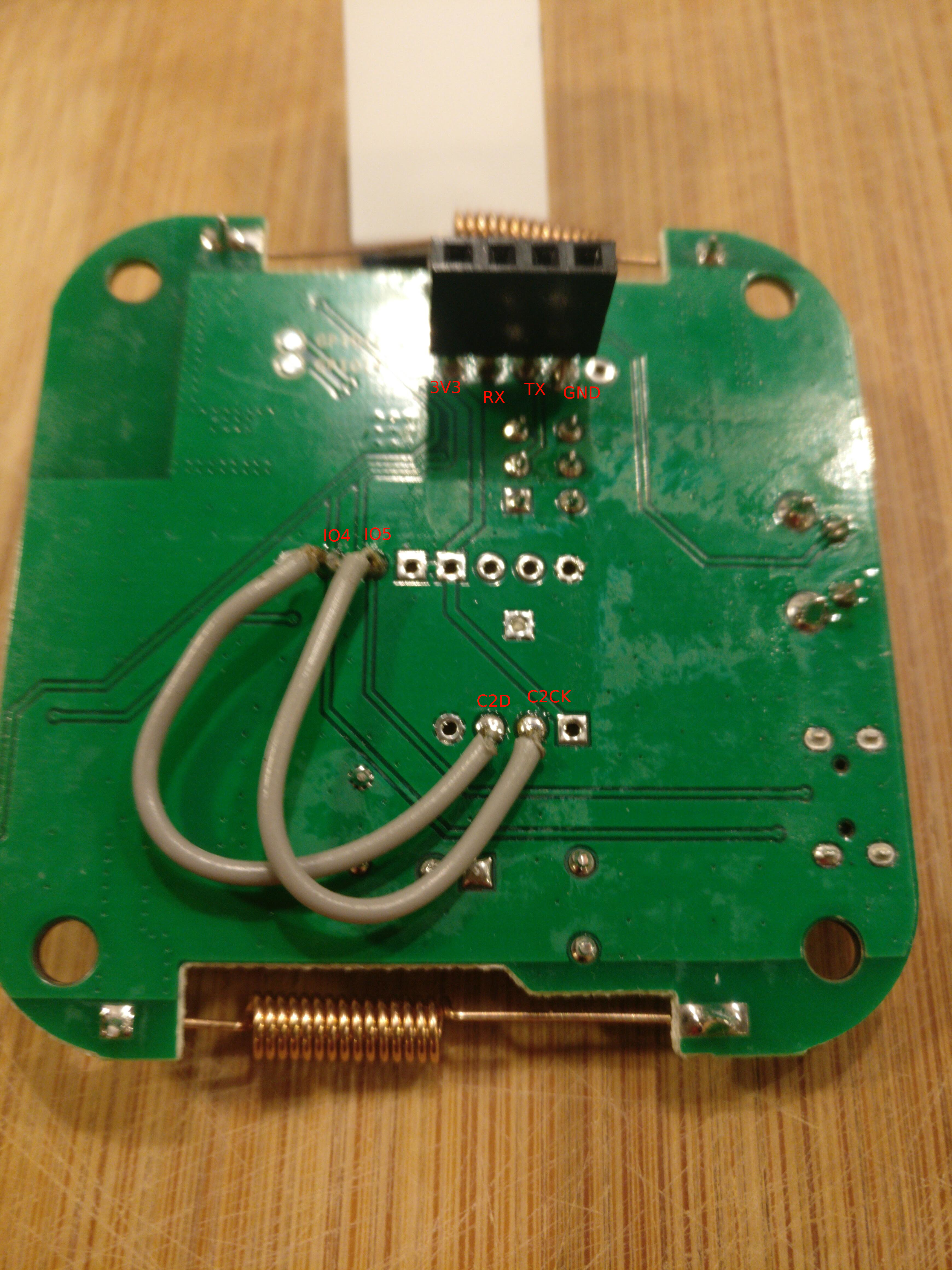
5 years ago i also have no luck to flash my new sonoff bridge. as i checked the wiki 10 times (as some advised here), i think the image for the new-version her in this thread as on the wiki is somehow wrong. !?
the wiki states:
Connect two wires between GPIO4 and C2Ck and GPIO5 and C2D.but if you check the image and revert the PCB, the wires should be crossed.
all you guys flashed successfully made it right, all others are irritated about some (maybe) misleading information in the wiki? any hints, if the image in the wiki is right, or my board is different?

ozett
commented
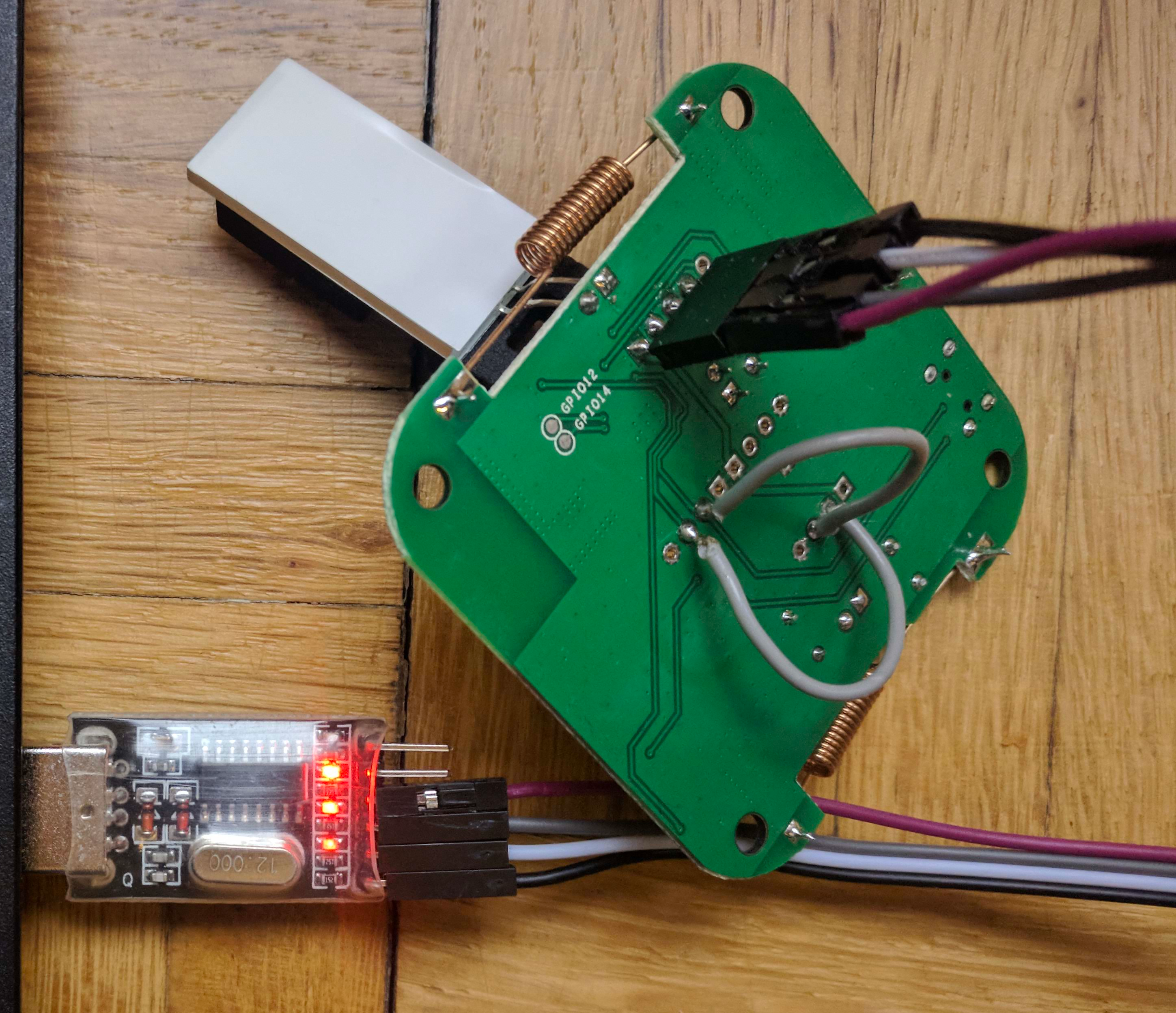
5 years ago i investigated, soldered headers, and did it again: i worked.
this is how i did it: wired cross-over rx-tx as i followed the hint which was linked above (also stated here)
(3.3V to 3.3V, RX to TX, TX to RX and GND to GND).followed the stated wiring for the new-PCB as "written" in the wiki and ignored the image:
Connect two wires between GPIO4 and C2Ck and GPIO5 and C2D.hold the button for 5 sec. down (not shorter) as stated here on usb-plugin of the ftdi
as the compiling takes a while in the arduino-ide i STRG-ALT-S exported a binary, put it in the flashtool directory and used this flashtool (took it from the espeasy-release.zip file)

it flashed:

ozett
commented
5 years ago at least i am on the module now to check if it works.
but as there are a bunch of modules/names one get confused again.. 😁
maybe would be good to reference the modules also by number in the wiki?
(just to make clear that this "bridge" is not any other "bridge", than as long as there are already numbered in the firmware and in the dropdown a number seems clearer )

TerryLansdown
commented
5 years ago Hi, I can confirm that for me, ozett's clarification is working (many thanks!). Module seems stable so far.
See attached pic of my 'revised' wiring, I'd used the image posted above (by joecool99) initially, with no luck, just reboot cycles.

 Fietspomp86
commented
5 years ago
Fietspomp86
commented
5 years ago I flashed mine according the wiki. I have a R2 V1.0.
So my wires are not like yours. Also I cut the 2 lines.
Flashed Tasmota using the normal procedure (Used ESPeasy flasher with precompiled binary).
Then flashed the hex file using the web-interface of Tasmota.

claud9999
commented
5 years ago I flashed mine according the wiki. I have a R2 V1.0. So my wires are not like yours. Also I cut the 2 lines. Flashed Tasmota using the normal procedure (Used ESPeasy flasher with precompiled binary). Then flashed the hex file using the web-interface of Tasmota.
Joy for me, I:
JOY! Thanks folks, now to try out my Sonoff 433Mhz goodies.
EDIT: Had trouble pairing my PIR sensor until I switched SW2 back on. Be sure to do that before reassembling!
 Villhellm
commented
5 years ago
Villhellm
commented
5 years ago I have successfully flashed my R2 V1.0 without resoldering/cuttiing traces, but the bridge is not receiving any signals from my RF devices. The switch is definitely set back to the on position, still nothing. Anyone have a similar problem?
 tedsluis
commented
5 years ago
tedsluis
commented
5 years ago I am having problems with the RF bridge R2 v1.0 marked "2017.11.23". It looks like flashing went okay, no errors, but after powering the RF bridge using the micro usb I can not connect to it.
To flash I use a Fedora linux system with a CH340G USB serial adapter. I use VSCode with the PlatformIO plugin. I tried the Sonoff-Tosmota 6.4.1 (release) and the 6.4.1.9 (development). I have quite some experience with successful flashing other Sonoff devices, like Basic, Pow R2, 1CH and S26.
I did not used the micro usb power during flashing, so I did not cut the copper traces on the board, as mentioned in the wiki.
Like @ozet, I was confused by the instructions in the wiki on the flash process. The image was different then the wiki text?! So I first tried the wiring according the image in the wiki and later on, as mentioned by @ozet, I also tried the wiring as advised in the wiki text.
My board (with wiring according wiki image, this does not match with the wiki text):

Wiring according the wiki image:
Wiring according wiki text:

Both ways of wiring gave the same result: The flashing process finished successful, but I was not able to connect to RF bridge.
The Flash logging is the same for both ways of wiring:
> Executing task: platformio run --target upload <

Processing sonoff (framework: arduino; platform: espressif8266@1.8.0; board: esp01_1m)
-------------------------------------------------------------------------------------------------------------------------------------------------------------------------------------------
Verbose mode can be enabled via `-v, --verbose` option
CONFIGURATION: https://docs.platformio.org/page/boards/espressif8266/esp01_1m.html
PLATFORM: Espressif 8266 > Espressif Generic ESP8266 ESP-01 1M
HARDWARE: ESP8266 80MHz 80KB RAM (1MB Flash)
Converting sonoff.ino
Library Dependency Finder -> http://bit.ly/configure-pio-ldf
LDF MODES: FINDER(chain) COMPATIBILITY(soft)
Collected 53 compatible libraries
Scanning dependencies...
Dependency Graph
|-- <OneWire> 2.3.2
|-- <ArduinoJson> 5.11.2
|-- <LiquidCrystal_I2C>
|   |-- <Wire> 1.0
|-- <TasmotaMqtt> 1.0.0
|-- <Adafruit ILI9341> 1.2.0
|   |-- <Adafruit GFX Library> 1.2.9
|   |   |-- <SPI> 1.0
|   |-- <SPI> 1.0
|-- <PubSubClient> 2.6
|-- <ESP8266WebServer> 1.0
|   |-- <ESP8266WiFi> 1.0
|-- <DNSServer> 1.1.0
|   |-- <ESP8266WiFi> 1.0
|-- <ESP8266mDNS>
|   |-- <ESP8266WiFi> 1.0
|-- <I2Cdevlib-MPU6050>
|   |-- <I2Cdevlib-Core>
|   |   |-- <Wire> 1.0
|-- <NeoPixelBus> 2.2.9
|   |-- <SPI> 1.0
|-- <ESP KNX IP Library> 0.5.1
|   |-- <ESP8266WiFi> 1.0
|   |-- <EEPROM> 1.0
|   |-- <ESP8266WebServer> 1.0
|   |   |-- <ESP8266WiFi> 1.0
|-- <ArduinoOTA> 1.0
|   |-- <ESP8266WiFi> 1.0
|   |-- <ESP8266mDNS>
|   |   |-- <ESP8266WiFi> 1.0
|-- <Ticker> 1.0
|-- <Adafruit SSD1306> 1.1.2
|   |-- <Adafruit GFX Library> 1.2.9
|   |   |-- <SPI> 1.0
|   |-- <Wire> 1.0
|   |-- <SPI> 1.0
|-- <I2Cdevlib-Core>
|   |-- <Wire> 1.0
|-- <ESP8266HTTPClient> 1.1
|   |-- <ESP8266WiFi> 1.0
|-- <ESP8266httpUpdate> 1.2
|   |-- <ESP8266HTTPClient> 1.1
|   |   |-- <ESP8266WiFi> 1.0
|   |-- <ESP8266WiFi> 1.0
|-- <TasmotaSerial> 2.2.0
|-- <Adafruit CCS811 Library> 1.0.0
|   |-- <Wire> 1.0
|-- <Waveshare esp 2.9 inch e-paper display driver> 1.0
|   |-- <SPI> 1.0
|-- <C2Programmer> 1.0.0
|-- <IRremoteESP8266> 2.5.2
|-- <Adafruit SGP30 Sensor> 1.0.2
|   |-- <Wire> 1.0
|-- <SPI> 1.0
|-- <Joba_Tsl2561> 2.0.7
|   |-- <Wire> 1.0
|-- <BME680_driver-bme680_v3.5.9>
|-- <Wire> 1.0
|-- <I2Cdevlib-ADS1115>
|   |-- <I2Cdevlib-Core>
|   |   |-- <Wire> 1.0
|-- <MQTT> 2.4.0
|-- <TasmotaModbus> 1.1.0
|   |-- <TasmotaSerial> 2.2.0
|-- <Mutichannel_Gas_Sensor> 0.0.1
|   |-- <Wire> 1.0
|-- <Adafruit LED Backpack Library> 1.1.6
|   |-- <Adafruit GFX Library> 1.2.9
|   |   |-- <SPI> 1.0
|   |-- <Wire> 1.0
|-- <ESP8266WiFi> 1.0
|-- <NewPing> 1.9.1
|-- <Adafruit GFX Library> 1.2.9
|   |-- <SPI> 1.0
|-- <rc-switch> 2.6.2
Compiling .pioenvs/sonoff/src/sonoff.ino.cpp.o
Linking .pioenvs/sonoff/firmware.elf
Retrieving maximum program size .pioenvs/sonoff/firmware.elf
Building .pioenvs/sonoff/firmware.bin
Checking size .pioenvs/sonoff/firmware.elf
Memory Usage -> http://bit.ly/pio-memory-usage
DATA:    [======    ]  58.9% (used 48240 bytes from 81920 bytes)
PROGRAM: [=====     ]  51.4% (used 526764 bytes from 1023984 bytes)
Configuring upload protocol...
Looking for upload port...
Use manually specified: /dev/ttyUSB0
Uploading .pioenvs/sonoff/firmware.bin
Uploading 530912 bytes from .pioenvs/sonoff/firmware.bin to flash at 0x00000000
................................................................................ [ 15% ]
................................................................................ [ 30% ]
................................................................................ [ 46% ]
................................................................................ [ 61% ]
................................................................................ [ 77% ]
................................................................................ [ 92% ]
.......................................                                          [ 100% ]
============================================================================== [SUCCESS] Took 62.11 seconds ==============================================================================

======================================================================================== [SUMMARY] ========================================================================================
Environment sonoff              [SUCCESS]
============================================================================== [SUCCESS] Took 62.11 seconds ==============================================================================
During flashing the LEDs on the CH340G USB serial adapter are flashing all the time, the big green LED of the RF bridge is green all the time. No other LEDs on the board flashes and I did not hear a beep.
There is one strange thing to mention about the flash process. Normally with all the other Sonoff devices I have flashed (using the same software and configuration), the upper and lower LED on the CH340G were "ON" when the flash process was fished. With the RF bridge only the upper LED was "ON".
Steps after flashing:
Again the big green LED of the RF brigde is green. No other LEDs on the board flashes and I did not hear a beep.
I tried to connect to the RF bridge board, without success. It does not react on pressing the button.
Of course I have repeated the flash process several times. Many times I first erased the firmway using this command:
$ ./esptool.py --port /dev/ttyUSB0 erase_flash
esptool.py v2.6
Serial port /dev/ttyUSB0
Connecting....
Detecting chip type... ESP8266
Chip is ESP8285
Features: WiFi, Embedded Flash
MAC: 60:01:94:be:7d:d1
Uploading stub...
Running stub...
Stub running...
Erasing flash (this may take a while)...
Chip erase completed successfully in 0.0s
Hard resetting via RTS pin...
I am still puzzled about the correct way of wiring. Can any one confirm the correct wiring for my type of board?
Isn't strange that I am able to flash the the RF bridge, but that it does not work? What can be wrong?
I even tried a second RF bridge and I ended up with the same results.
How can I debug this?
TerryLansdown
commented
5 years ago How can I debug this?
Hi, See my earlier post for the wiring that works for me.
Sounds like you know what you're doing, but maybe you didn't try:
What do you mean by 'I was not able to connect to RF bridge'? Is it dead? Can you ping it, but not connect to the web interface? On mine, powering by the micro-usb cable resulted in clicking reboots, until I fixed the wiring.
tedsluis
commented
5 years ago Hi, thnx for your extensive reply!
TerryLansdown said:
Hi, See my earlier post for the wiring that works for me.
Sure I have read your post, but it was/is not 100% clear to me whether your board has the "2017.11.23" mark, like my board. Can you confirm that?
TerryLansdown said:
- checking the serial monitor for device boot/network connect messages? I think I tested mine with the USB-serial cable powering it, first.
I tried that, but without luck. I am not sure how to do it on a Sonoff RF Bridge. I had my RF bridge connected using the TX, RX, 3v3 and GND to the CH340G serial adaptor. I did not connected it to a micro usb power. Is that correct? I tried the cu command (Fedora command line, I have used this for other board successfully):
$ cu -l /dev/ttyUSB0 -s 19200I didn't got any response. How should it react? I also tried to put the RF bridge in flash mode, in order to get any response. What steps should I take to start a console? What tool did you use?
TerryLansdown said:
- checking if the bridge is appearing on your network, ping'ing it?
The IP address of the bridge did not appear in my network. So I could not ping it or connect to the web interface.
TerryLansdown said:
- flashing a different way? I used the Arduino SDK to flash mine.
I will try that, may be tonight (or in the coming days).
TerryLansdown said:
On mine, powering by the micro-usb cable resulted in clicking reboots, until I fixed the wiring.
My wiring is like yours now. When I power on the RF bridge using the micro usb, the big green LED turns "on". No other LED flashes, no beep and no reaction when I press the button.
I used the same Sonoff-Tasmota firmware + configuration as I used for other Sonoff devices (except for the IP address and topic name).
To flash the RF bridge I tried an upload speed of 115200 as well as 19200 (takes much longer to finish). Which is correct?
To test whether my current Vscode with PlatformIO setup still works, I have flashed a Sonoff Basic device yesterday. It still works.
TerryLansdown
commented
5 years ago Hi,
Don't know, it's now deep in a cupboard put back together. If I get a chance I'll have a look, from memory it was a 2017 version.
Again (from memory), I flashed with just the USB-Serial adapter. When uploaded, within the Arduino SDK there is a serial monitoring option. Using only the serial adapter (I think) I got status updates, connected to local network, connected to MQTT server, etc. You may have seen these with your Sonoff Basics? Only after a successful flash (using the Arduino SDK and the image from the main Tasmota Git pages; did I unplug the serial and power using just micro-usb cable.
I'm guessing your flash is a big fail if you can even see noise using 'cu'. Think you did the right thing to zero out the board between each flash with esptool.
I don't think I needed to press any buttons to get the board up. Move onboard switch from flash to broadcast, then plug in and it connected to my network, and MQTT server. I could then access the webpages, much like (presumably) your other Sonoffs.
From memory, I think I tried flashing at both speeds, I think it flashed at 115200 and then it definitely communicates at 19200.
Other than trying a different flashing technique specifically for this board, sorry I'm out of ideas.
tedsluis
commented
5 years ago Hi, Thanx again for your detailed answer.
I think you are right, mine RF bridge is not flash successful.
I tried flashing using the esptool, several attempts with different baud rates, but they all ended like this:
[esptool-2.6]$  ./esptool.py --baud 19200  --port /dev/ttyUSB0 write_flash -fs 1MB -fm dout 0x0 /home/tedsluis/Downloads/sonoff.bin
esptool.py v2.6
Serial port /dev/ttyUSB0
Connecting....
Detecting chip type... ESP8266
Chip is ESP8285
Features: WiFi, Embedded Flash
MAC: 60:01:94:be:7d:d1
Uploading stub...
Running stub...
Stub running...
Configuring flash size...
Compressed 561728 bytes to 383685...
Wrote 561728 bytes (383685 compressed) at 0x00000000 in 201.8 seconds (effective 22.3 kbit/s)...
File  md5: d4d8fc948a61ad6daba006cfb13ba547
Flash md5: 3a870a291785e4cc40d1af355e578b7c
MD5 of 0xFF is 9300bbcef90645be31241ea9ba92847b

A fatal error occurred: MD5 of file does not match data in flash!
I will try the Arduino IDE to night.
ozett
commented
5 years ago may you try the espeasy flashtools? i had success with them: https://github.com/arendst/Sonoff-Tasmota/issues/1916#issuecomment-452069128
 LucReynders
commented
5 years ago
LucReynders
commented
5 years ago Received my RFBridge yesterday. Flashed it with Tasmota : (! no extra wires have been added, only the pins - no 5V supply during flash))
tedsluis
commented
5 years ago Thnx @TerryLansdown, @Ozett and @LucReynders.
@TerryLansdown said:
The Arduino SDK worked for me, good luck.
It took me a while to get the Arduino IDE working on Fedora Linux. I guess most people use Windows. I followed the wiki instructions and I managed to build and upload the Sonoff-Tasmota firmware. Unfortunately still the same result: I can not connect to the bridge, but I keep positive. This is only my first attempt with the Arduino IDE :-)
Build options changed, rebuilding all
Archiving built core (caching) in: /tmp/arduino_cache_674523/core/core_esp8266_esp8266_generic_CpuFrequency_80,VTable_flash,ResetMethod_nodemcu,CrystalFreq_26,FlashFreq_40,FlashMode_dout,FlashSize_1M0,led_2,LwIPVariant_v2mss1460,Debug_Disabled,DebugLevel_None____,FlashErase_none,UploadSpeed_115200_c1df69fc8c56a963385ffb471ec2f0ff.a
Sketch uses 529928 bytes (51%) of program storage space. Maximum is 1023984 bytes.
Global variables use 51604 bytes (62%) of dynamic memory, leaving 30316 bytes for local variables. Maximum is 81920 bytes.
Uploading 534080 bytes from /tmp/arduino_build_804524/sonoff.ino.bin to flash at 0x00000000
................................................................................ [ 15% ]
................................................................................ [ 30% ]
................................................................................ [ 45% ]
................................................................................ [ 61% ]
................................................................................ [ 76% ]
................................................................................ [ 91% ]
..........................................                                       [ 100% ]
No output on the serial monitor yet, but I need some more time to get to know the Arduino IDE.
@Ozett said:
may you try the espeasy flashtools?
Unfortunately I only have Linux systems. I think espeasy only runs on Windows.
Your previous post is very useful!
@LucReynders said:
Flashed it with Tasmota : (! no extra wires have been added, only the pins - no 5V supply during flash))
No extra wiring? Very interesting. Is your RF bridge marked "2017.11.23"? Thnx for your detailed steps. Very useful!
I need some more time to carry out all the instructions and tips. I let you guys know in the coming days.
ozett
commented
5 years ago Unfortunately I only have Linux systems. I think
espeasyonly runs on Windows. Your previous post is very useful!
Thanx, Espeasy is a firmware for the ESP8266/Esp32 chips. they have also firmware flash-tools. i think there is a linux-variant of the good working windows tool.
may there some inspirations for your experiment: https://www.letscontrolit.com/wiki/index.php/Flash_script_linux
---add: as i looked your output of the arduino ide: do you hard-reset (power-off!) your device after flashing? i think that is needed also...
LucReynders
commented
5 years ago For flashing the RFBridge, look at :
https://www.youtube.com/watch?v=XixXbg2T4Ns
https://no-ads-youtube.com/video-without-adverts/drzzs/sonoff-rf-bridge-with-tasmota?v=OfSbIFIJPuc
 molexuse
commented
5 years ago
molexuse
commented
5 years ago I have successfully flashed my R2 V1.0 without resoldering/cuttiing traces, but the bridge is not receiving any signals from my RF devices. The switch is definitely set back to the on position, still nothing. Anyone have a similar problem?
Hi
Same problem. Flash without cut. It`s works, wifi connects. mqtt connects.
Rf received (red led flash) but in console serial and mqtt rf not send. I try diferent firmware with no success.
As i understand from schematic esp communicate with rf chip by uart, still analyze....

UPDATE! It`s works!!! flash sonoff-classic.bin from git release and all ok
LucReynders
commented
5 years ago !!! Noot all remontes are detected by the bridge, only the 24 bit codes. In my case only one out of 3.
Today i get my "new" Bridge, successfully flashed with help of the good work here. Thanks for that.
I want to share my experience
What i did differnt from the description:
The Box is Screwed together.
To get to the Switch, just bend slightly the large Led on the Top
Then Flash it from Bottom Side
regards