 Jason2866
commented
6 years ago
Jason2866
commented
6 years ago Closed FamJohansson closed 6 years ago
Jason2866
commented
6 years ago  FamJohansson
commented
6 years ago
FamJohansson
commented
6 years ago There are two versions of 4CH pro I have R2 version ..
see pictures


Jason2866
commented
6 years ago Do you have checked that the pinheader goes to the correct pins of the esp? For flashing GPIO 0 must be grounded before the power goes up from the USB seriell chip... Nearly all sonoffs use a button wired to GPIO 0. Do you have a Ohm meter, to measure this things out? Perhaps you have to set the litte switch to the other position for flashing. -> see Rf Bridge I could be that the other big chip is connected via serial and with the switch you disconnect it. Just try to read the flash with esptool with this setting. Save the Rom. If sonoff firmware doesnt work you could use it with the original. Just flash it back... Pinout https://goo.gl/images/VpDvEV
 nmaggioni
commented
6 years ago
nmaggioni
commented
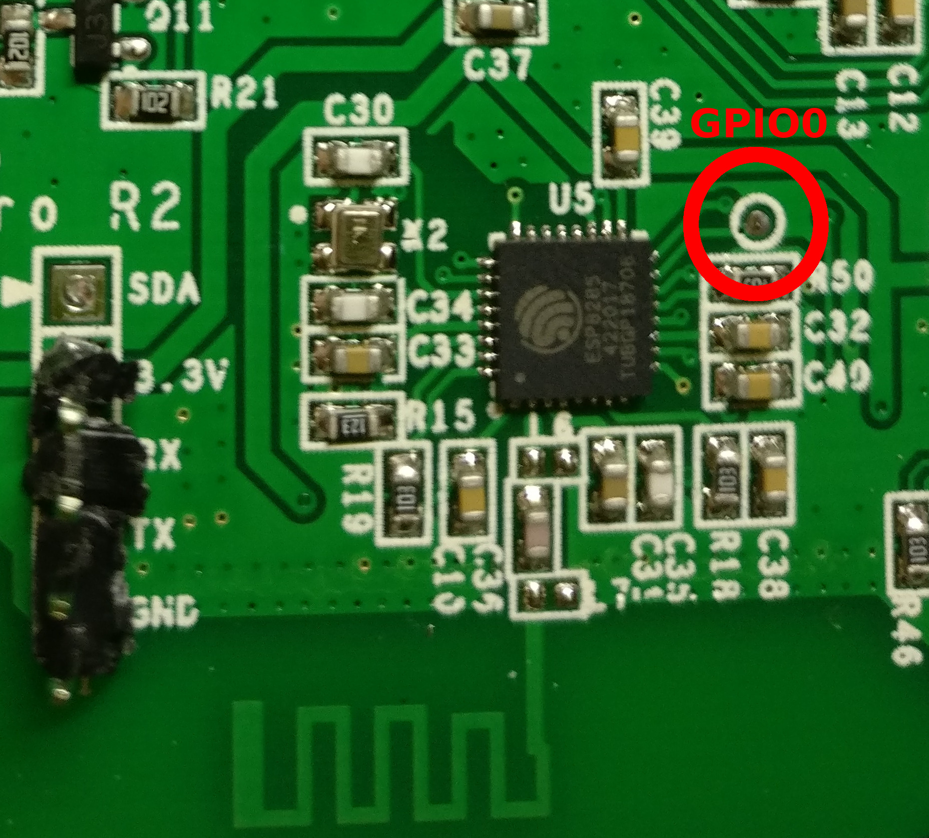
6 years ago On the R2 model the GPIO0 pad is broken out to a small pad to the right of the ESP package, as per my other comment - I have updated the wiki:
FamJohansson
commented
6 years ago @nmaggioni Thanks this solved my question..
nmaggioni
commented
6 years ago @FamJohansson You're welcome, consider closing this issue if it's fixed.
FamJohansson
commented
6 years ago Hello again @nmaggioni Do yo have any clue how to flash this one?
nmaggioni
commented
6 years ago The ESP module looks like the one in the 4ch Pro, have you tried its method as per the wiki? Search for a datasheet and check the GPIO0 pin position in case it differs.
 sigalou
commented
6 years ago
sigalou
commented
6 years ago For Flash, I did a tutorial on my site (in French). Good continuation. http://sigalou-domotique.fr/index.php/17-sonoff-4ch-pro-r2
FamJohansson
commented
6 years ago @sigalou Have you tested this one?
https://www.aliexpress.com/item/32835664788/32835664788.html
Can’t see how to flash it,
Jason2866
commented
6 years ago Looks interesting, but i am pretty sure it is not a genuine sonoff. ITEAD had never used an extra power supply board (this looks like a cheap one) and the integrate the ESP on the main PCB on actual board revisons. Furthermore this board istnt listed on the website from ITEAD
 ascillato
commented
6 years ago
ascillato
commented
6 years ago Hi @FamJohansson
If your issue is solved, please close it. Thanks! :+1:
 KierkelsD
commented
6 years ago
KierkelsD
commented
6 years ago @FamJohansson , could you tell us how you have resolved your problem?
Thanks
 Frigorio
commented
5 years ago
Frigorio
commented
5 years ago Hello again @nmaggioni Do yo have any clue how to flash this one?
 itajackass
commented
5 years ago
itajackass
commented
5 years ago Hi i'm little bit OT but i've found some pic here... Is it possible to install an external antenna on R2 version? In normal version was a pad where we can solder an ipex connector. But in R2 i don't see anything. Can someone help me?


Hi, Thank you for a wonderful job you've done with Sonoff Tasmota.
I'm trying to flash my Sonoff 4CH Pro R2 with the firmware but I do not get it uploaded. A little bit uncertain of what I'm doing wrong.
I have no trouble flashing the Sonoff 4CH Pro. (Current version 5.12.0c)
I'm unsure of the following: -Supports sonoff Tasmota Sonoff 4CH Pro R2? -How do I put Sonoff 4CH Pro R2 in flash mode?