arendst / Tasmota

Alternative firmware for ESP8266 and ESP32 based devices with easy configuration using webUI, OTA updates, automation using timers or rules, expandability and entirely local control over MQTT, HTTP, Serial or KNX. Full documentation at
https://tasmota.github.io/docs
GNU General Public License v3.0
21.87k stars 4.75k forks source link

Adding support for PZEM004T energy monitor for 3 phase - request #2315

Closed roblad closed 4 years ago

roblad commented 6 years ago

Hi,

Is it possible add USE_PZEM004T and add support for PZEM004T Energy monitor for 3 phase by using USE_SERIAL_BRIDGE and report each phase through that functionality ? May be there is possibility to use 3 phase config for USE_PZEM004T as it is in that project:

https://github.com/apreb/eNode

sendorm commented 4 years ago

I know this issue is closed but I am having difficulties implementing the procedure. When I do the

13:49:17 CMD: SerialSend5 01040000000A700D
13:49:17 MQT: stat/black/RESULT = {"SerialSend":"Done"}

OR with the new command: ModuleAddress 3

How can I be sure that the address is changed indeed? All I get is stat/black/RESULT = {"SerialSend":"Done"}

localhost61 commented 4 years ago

Try the command ModuleAddress alone, with no argument.

jziolkowski commented 4 years ago

@localhost61 no, it won't work. This is command is write-only, it won't query the Module for current address, because how would it know where to send the query?

@sendorm the only way to check if it worked is to connect the configured PZEM to AC (so it will present itself as ready) and reboot Tasmota. If the PZEM data is visible, then it worked. Disconnect, attach the next one and do the procedure again after restart.

sendorm commented 4 years ago

When the tasmota is restarted, the web gui briefly shows the 0/0/230. From the location of the valid voltage I can verify that the address change command is working. Thank you. But when I try to connect two phases it fails, all the voltages show 0. And it converts to the 1 phase system. To verify: This code also works for 2 phase setup and the cathode of the diode(the side with the black line) is connected to the tx port of the pzem right? One guy in the thread mentioned changing the polarities of the diodes works for him. I might try that too. (edit: That also didn't work)

localhost61 commented 4 years ago

Don't you have a multimeter with a diode mode to test the junction? Sorry, I've no device for testing.

sendorm commented 4 years ago

I do have a multimeter and the forward drop is 0.27Volts, which seems to be in order. I also tried changing the Vdd to another source. I was using the VU port of 8266 (which worked for one pzem004t). This also didn't change the behavior. Maybe I should try another source. Also my pzem's are version 2. My tasmota version is as follows:

Program Version 6.7.1(sonoff)
Build Date & Time   2019-10-26T13:19:13
Core/SDK Version    STAGE/2.2.2-dev(38a443e)
sendorm commented 4 years ago

I couldn't manage to get this working. I guess I'll just add another tasmota for the second phase :) Thanks everyone. Edit: I should also mention that I was not using the 1K mod with pzem004t v2 and it was still working fine.

jziolkowski commented 4 years ago

@arendst in its current form, is it possible to use a rule to trigger against a variable for a certain phase? For example, rule triggering only if the 2nd value in the Power list is >= \<value>

Maybe a new set of triggers in a form of Energy#power\<L> or energy#current\<L> etc where L <= the number of currently reported "phases". OR maybe a new setoption which configures how the telemetry is formulated, so instead of "Power": [a,b,c] we'll get "Power1": a, "Power2": b ... and so on.

edit: \< escaping

arendst commented 4 years ago

Since list support is implemented a while ago you might want to try this:

on energy#power[2]>0.68 do publish cmnd/wemos4/theo %value% endon
rt400 commented 4 years ago

Recently, there seems to be disconnections in the communication of the modules. For example: image image image

And sometimes I get crazy and illogical values: For example :

image

and after seconds : image

any idea ???? use with WEMOS D1 with 6.7.1v

Jason2866 commented 4 years ago

@rt400 How is everything wired? Do yyou have a good power supply? Do NOT connect anything to the 3.3V path of wemos mini. The 3.3 V reg is not capable to drive anything...

rt400 commented 4 years ago

@Jason2866 I Used with 5v 2.1A power supply . and the 3 PZEM module connect 5v from the WEMOS. also the TX from the 3 module are conncet with Shtoky Diode .

Jason2866 commented 4 years ago

Which 5V 2.1A power supply? Dont use cheap china USB ones...

sendorm commented 4 years ago

@rt400 do you use the 1k resistor fix, can you provide a picture of your setup and also what are your pzem’s versions? Thank you

localhost61 commented 4 years ago

@rt400 I guess you mean the 10kΩ pullup. 1kΩ may be too much current to sink for the slave to achieve a low level.

Jason2866 commented 4 years ago

The 1k resistor is needed on every Pzem device to make the TTL level compatible to 3.3V The 10k resistor is needed as bus pullup! So you have to install 3 pieces of 1k resistors and one 10k resistor

sendorm commented 4 years ago

@Jason2866 When the 1K is connected, the pzem is still powered with 5Vs right?

localhost61 commented 4 years ago

@sendorm Yes! That's the reason why.

sendorm commented 4 years ago

Ok. I have pzem004t v2’s and they do readily work with no 1k ohm and being directly connected to 5V with a 8266. Could not get any info on the net on v2 sensors and what is the difference with v1. Could not get to use them with the schottky diodes and 3 phase setup though. Well I just bought v3’s in the mean time.

localhost61 commented 4 years ago

ESP8266 is powered in 3.3V and not more than 3.6V, There is a voltage regulator on a Wemos D1 mini that convert the 5V into 3.3V. It's really not advisable to interconnect the ESP I/O with 5V powered sensors without caution. There are protection diodes on every ESP I/O intended to shorten voltage spikes over 3.6V. If the overvoltage duration is too long, those diodes will blow and the MCU will follow soon. With 1kΩ serial resistor you reduce the stress on the ESP I/O and the protective diodes will be able to handle the overvoltage.

sendorm commented 4 years ago

ok thank you and you are right. But I just couldn’t get the pzems to work when a 1K is connected. Also the CEO, Teo Swee Ann has stated that pins are indeed 5V tolerant. https://www.facebook.com/groups/1499045113679103/permalink/1731855033731442/?hc_location=ufi Mind you that my pzems are v2.

localhost61 commented 4 years ago

Thank's for the input ;-)

rt400 commented 4 years ago

@Jason2866 @localhost61 What about the 10K resistor pull-up you mean ??? here is my schema image

localhost61 commented 4 years ago

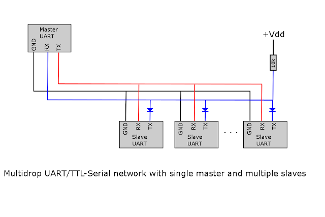
@rt400 Your schema has several divergencies with the one @0x3333 provided here.

Following Telecom industry standards, RX and TX are intended to be crossed because RX is a Receiver and TX a Transmitter, some manufacturer add confusion when they write on the Sensor pinout the label of the MCU pins they connect too. It applies for buses and is more intuitive for newbies, but it's wrong for "point to point" serial connection.

I remind I have no experience with PZEM, I only own Eastron SDM modbus and Neo Coolcam energy monitors.

rt400 commented 4 years ago

@localhost61 i correct the schema. i draw by mistake but on real its in cross.. in @0x3333 schema he connect from 5v a 10Kohm resistor to TX . so the VCC connect direcly to 5v ? don't understantd exacly the schema..

Jason2866 commented 4 years ago

Yes, you connect 5V via the 10k Ohm resistor to the TX line which goes to RX input of the ESP This resistor is called "PullUp" without this resistor it will 100% NOT work

rt400 commented 4 years ago

@Jason2866 thank.. so one wire from ESP 5v to PZEM 5V and add resistor from ESP 5v to ESP TX ?

Jason2866 commented 4 years ago

Add resistor to the line where the diodes are where it goes to ESP

rt400 commented 4 years ago

@Jason2866 OK i will add it and respond if the problem was fixed. many thanks

Jason2866 commented 4 years ago

I clarified my text!

localhost61 commented 4 years ago

Wemos mini 5V, not ESP 5V, on the module the ESP run at 3.3V

rt400 commented 4 years ago

@Jason2866 with adding the pull-up resistor won't fix the problem , but i install diffrent power supply and now its look ok. i keep check it..

sheminasalam commented 4 years ago

Can I use the transformer coil with the phase wire instead of the neutral wire to read the values? I know the coil is instructed to be used with neutral wire. But in my case there is no separate neutral wires for the 3 phases and i want to read the values of all the three phases separately. How can I do this if there is no separate neutral line for each phases?

jziolkowski commented 4 years ago

I use my CT's on L wires and it works well. TBH I have no idea how else you could measure 3 phase installation using N wire only, because by design 3 phase has only one N wire.

sheminasalam commented 4 years ago

I have two questions. 1) what are the specifications of the ph junction diode used to connect to TX? 2) If i use a sonoff basic instead of wemos, do i have to connect a 5v external power supply with 10k resistor to TX ?

Jason2866 commented 4 years ago

1) schottky diode like BAT45 2) dont use a sonoff basic for

localhost61 commented 4 years ago

dont use a sonoff basic for

... security reason regarding hazardous voltage and only 3.3V, no 5V available.

sheminasalam commented 4 years ago

Actually its a salvaged sonoff basic which only works if i give 3.3v to the chip directly kind of the way we power up during flashing. The 220v input side is not usable so hazardous voltage is not an issue. I plan to use a 5v 2.5a dc power supply for the sonoff and the PZEMs. In case of the sonoff i will use a 5v to 3.3v converter. But what about the 5v with 10k resistor. Can i directly conncect the 10k resistor to this 5v power supply?

localhost61 commented 4 years ago

In that case, yes, it's the way to do.

sheminasalam commented 4 years ago

I am planning to use ESP01S as my master device which works with 3.3v volt. The above scheme has been discussed with wemos d1 mini in mind which uses 5v as input. I can see that the pullup resistor is connected to 5v vdd in case of TX pin of the salve and then to RX pin of wemos. In my case since the master device is working with 3.3v direct supply which I plan to obtain from a 5v to 3.3v converter, should I connect the pull up resistor of 10k to 3.3v as in the schema have uploaded or to the 5v as shown in the original schema? please advise. diode-level-converter

localhost61 commented 4 years ago

@sheminasalam ->10k to the 5V.

And, once again the ESP from the Wemos D1 mini is NOT powered with 5V but with the 3.3V supplied by the regulator located on the back of the PCB. Your schematic is confusing, and doesn't apply here. Where are the TX & RX signal pins? I only see power pins here. According to Espressif representative you can use a 10k pullup to 5V on the entries of an ESP powered in 3.3V, it won't fry.

sheminasalam commented 4 years ago

Ok Thanks.. I was suggested schottky diodes similar to BAT45 for connecting to TX of slave. I have IN4148 with me. Even though it is not a schottky diode it is fast switching. Can i use it instead of BAT45?

localhost61 commented 4 years ago

It may work but not as good as a BAT45. So use it for your tests in the meanwhile but get some BAT45 for the long term. Because we want a voltage drop as low as possible so that the RX pin see a Low level when one of the TX pins is low but the others high.

austrisv commented 4 years ago

I wonder, is it appropriate to ask here or shall it be a new issue or question here or in discord? I will give it a try and ready to move if this is not correct. I have Tasmota 7.1.2 running on Sonoff Basic R2 and two PZEM004 v3 attached to it (with 1k on 5V pin). I executed ModuleAddress 1 and 2 while having single module connected and it seems to be fine. It looks like all is working correctly with V+ pin attached to Sonoff's 3.3 and without the 10k pullup ... and without the schottky diodes. Question: am I missing something and it only appears to be working and may cause me headache in future? Or all should be ok? Thank You so much! image image

jziolkowski commented 4 years ago

Without the diodes you will sooner or later burn a device serial pin. If you have issues with that setup make sure your diode is of the exact type or at least VERY similar characteristics

austrisv commented 4 years ago

Without the diodes you will sooner or later burn a device serial pin. If you have issues with that setup make sure your diode is of the exact type or at least VERY similar characteristics

okkk, I had BAT43's ordered anyways, will add them then. TA!

austrisv commented 4 years ago

Without the diodes you will sooner or later burn a device serial pin. If you have issues with that setup make sure your diode is of the exact type or at least VERY similar characteristics

Added BAT43 and all seems working. One last q - do I still need the 10k pullup on Tx line? I have pzem's V+ connected to sonoffs 3.3v. Added two bat43's, do not have 10k pullup and all seems to be working. Or it won't last long like that? Thank You!

Jason2866 commented 4 years ago

Why only 2 diodes? You need all three. The pullup is needed. Do it as described or you will have sooner or later problems....

austrisv commented 4 years ago

Why only 2 diodes? You need all three. The pullup is needed. Do it as described or you will have sooner or later problems....

two because I have two pzems in my setup:) I was confused as original diagram did not show V+ connection from pzem to board. Well, at least, that's how I read the diagram. Will go with the pull-up. Thank You!

sheminasalam commented 4 years ago

Can anybody help me with programming different addresses to pzem. I am stuck. i have tried to change address. The problem now i see is that when i connect all three together as in circuit diagram i get zero as reading. But when i connect first and second pzem to sonoff through circuit diagram i get correct reading. similarly with one and three together i get correct reading. But when i connect 2 and 3 together i get zero as reading. so i believe the address of 2 and 3 are having issues. how to correct it?