 LurchiStromberg
commented
7 years ago
LurchiStromberg
commented
7 years ago @moonfarms Oh... I read that 3,3 Volts is Urgent not to damage the EPS Chip at flashing...
Its pretty confusing if some Guys here tell to read Wikis, but at the End all do different stuff lol
But of course i am thankful to see, that there is also a more easy Way.
One last question about the Flash Mode. If I hold the 2 Buttons and Power the Board with the mini USB nothing happens that Moment. After I release the 2 Buttons the Relais start to pulse. At the Moment i push the outer Button, both LEDs are solid.
Is that the Way it works?
 moonfarms

 jktz90
 arendst
 witek1308
 osmassoglia
 ashwinbangalore
 sabs01
 stepac
 branob
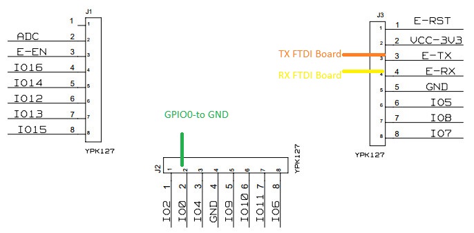
 For what it's worth, here is the pinout representing how it works with original firmware. Basically the two buttons and mode LED is also available on the pins. The remaining 3 pins are not connected to anything.
 ronwar
 TSparkas

 rmarkle
 tlc76
tlc76 PauloPC
 syphe
syphe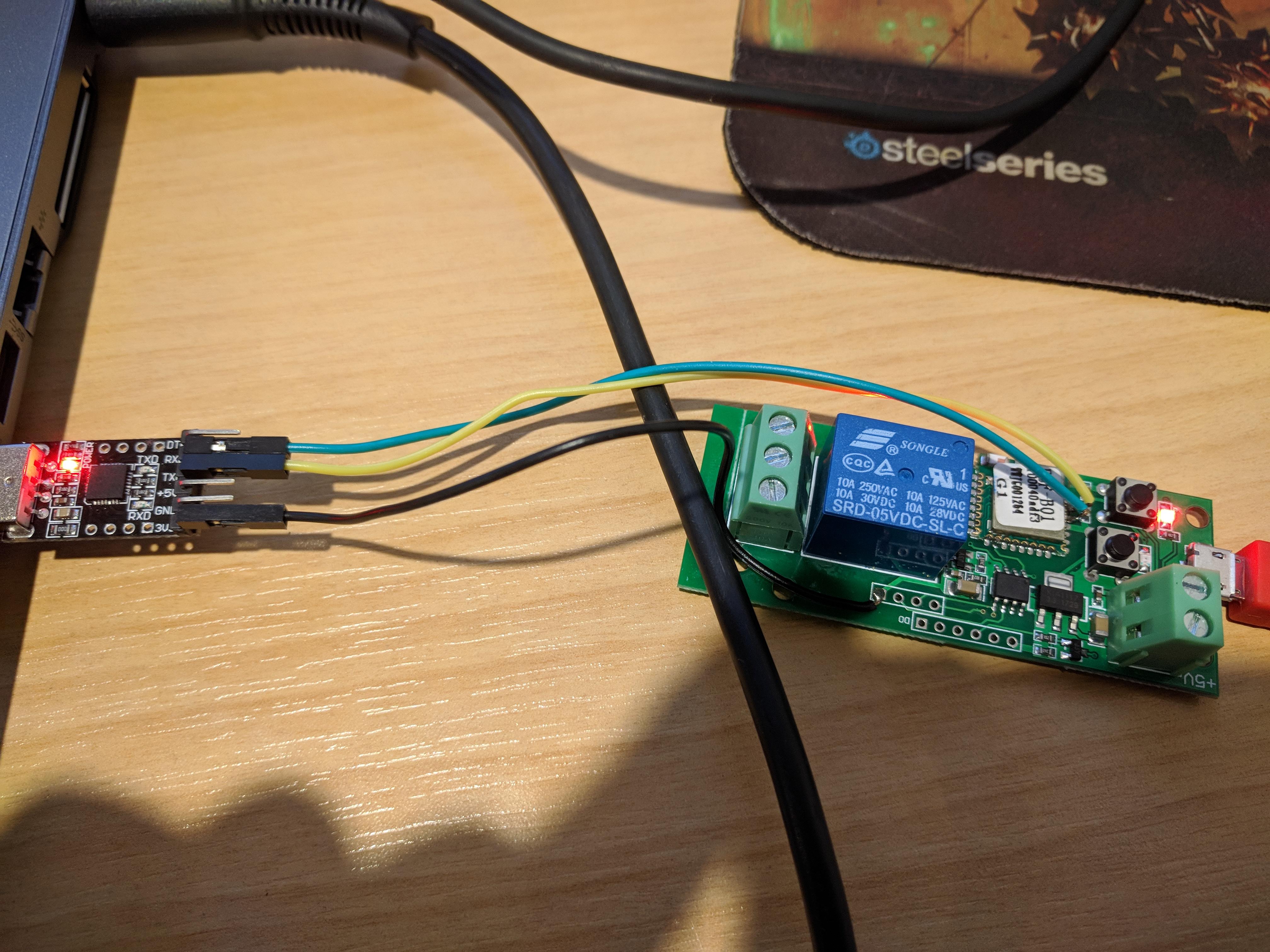


 antimix
 senadaruc
Hi All,
I just took possession of the above new device that appears to be the new version of the old device - the pics on the Itead website has not even been updated.
This board is based on the PSF-B01 itead ESP8285 module.
I have not found any custom firmware yet that appears to work - not Tasmota, ESPEasy or Espurna seems to work.
Using Tasmota it uploads fine with success flag - but this basically puts the module in an endless switch loop with no connection to wifi as setup in config file.
Anyone have any info?
Regards, Ed