 meingraham
commented
5 years ago
meingraham
commented
5 years ago Have you tried flashing the Tuya module via OTA?
Closed jim20j closed 5 years ago
meingraham
commented
5 years ago Have you tried flashing the Tuya module via OTA?
 jim20j
commented
5 years ago
jim20j
commented
5 years ago is the Raspbian 9 the method to use? i don't have another sd card right now.
meingraham
commented
5 years ago I flashed a fresh copy of Raspbian just for performing this. I would not think that using an existing Raspbian copy (perhaps updated to the latest packages) would not be any problem.
jim20j
commented
5 years ago according to the video it appears multiple steps and configs are involved, is this the only solution to this in the meantime? i am new to this but have been catching on pretty quick.
meingraham
commented
5 years ago This is the best OTA solution for Tuya modules. There are multiple steps but they are well documented and straightforward. The process is quite robust and foolproof. I would definitely recommend this over doing it via the serial interface.
Take a look at these videos for additional Tuya OTA flashing help: https://www.youtube.com/watch?v=O5GYh470m5k https://www.youtube.com/watch?v=q4HrpSORcXA https://www.youtube.com/watch?v=av84uORLB9Y
jim20j
commented
5 years ago Followed digiblurDIY, Success! The reason I couldn't find much help searching was because I was using the search string of how to flash "TYWE3S" instead of how to flash "Tuya"
Thank you!
meingraham
commented
5 years ago Glad to hear you got it done. For some of these devices you literally have to break the case open. And even then you sometimes can't get to the pins you need. Getting the OTA process for Tuya based devices (and they are everywhere) was huge!
Once you're in this for a bit (I just got started a few months ago), you begin to recognize model numbers, etc.
Please consider contributing a template for this device if it is not already in the template repository.
For ongoing assistance, a great place to get help is on the Tasmota Discord Chat.
If you're done here, please close this issue.
Mike
 Eiferer
commented
5 years ago
Eiferer
commented
5 years ago Hi,
My issue here is a problem with OTA has left me with the need to flash the hard way.. Any help, on how to get this unit into configuration mode?
 BreBar07
commented
5 years ago
BreBar07
commented
5 years ago I'm having issues getting my device into tasmota. I've tried OTA and flashing by serial no luck :(
OTA never detects device. Serial starts but fails shortly after.
I have single gang, double gang and power outlet I want to flash.


BreBar07
commented
5 years ago Tonight I confirmed the chip does go into programming mode but fails everytime. After numerous attempts I say it get as far as displaying 15% complete before failing. Anyone got ideas? I have seen one video CH_PD be connected to ground, but I don't think that's required.
 kozumin
commented
5 years ago
kozumin
commented
5 years ago Hi, did you manage to flash it? I'm in the same situation :( too late for OTA and the wiring method doesn't work. Mine is either not going in the boot mode (GRND+GPIO0) or boot mode is triggered in a way I don't know yet. Within the app works fine... but I want to add a few of them in HA It is a Wifi Leading Edge Dimmer : https://www.aliexpress.com/item/33015175004.html?spm=a2g0s.9042311.0.0.70da4c4dLDZmHi Any help?
BreBar07
commented
5 years ago No, mine definately goes into boot mode. U have been able to erase flash but it fails to upload flash everytime (fails at 8 or 12%) have tried different tools but same result :( if anyone can help I can donate a switch for testing....
kozumin
commented
5 years ago Is GPIO0 + GRND enough to put TYWE3S in boot mode? For me, the flashing process doesn't even start on UI... just waiting in a forever loop. The led goes solid green with the two pins wired but I'm not sure if that means is in boot mode. I'm using NodeMCU-PyFlasher and it worked nicely for all Sonoff modules I've flashed before.
meingraham
commented
5 years ago If any LEDs lit, it's likely not in programming mode. Connect GPIO0 to GND and hold the connection for 3-5 seconds while powering up the device to ensure the ESP completes the boot process before disconnecting GPIO0. Cycle power between erase_flash and upload if not using PyFlasher.
Also... this https://www.thingiverse.com/thing:3231225
kozumin
commented
5 years ago In my case, if I power the device (via USB-TTL) without shortcut of the two pins, the led is always off. If i shortcut them, the led goes green (and stays green). The jig is nice and I actually printed one but I couldn't find those pins at jaycar (NZ)... so I have to order them online.
kozumin
commented
5 years ago 

meingraham
commented
5 years ago The fact that something is driving a GPIO to turn on the LED makes me suspicious. That, along with the fact that when you do short GPIO0 to GND (regardless of the LED) and you can't flash the chip confirms that it isn't in programming mode.
A short command to check if it's in programming mode before trying to erase would be read_mac or flash_id. When you get a successful response from those commands, then the ESP is in programming mode and you can then erase_flash and then upload the firmware.
Did you check to see if perhaps the button is connected to GPIO0? Also, those 4 contact holes below the PCB information look like they could be the programing pins (Vcc, GND, Tx, Rx). Did you try checking if they traced back to the respective TYWE3S pins? I say this because I'm wondering if there could be some soldering issue (e.g., hidden under the TYWE3S itself) so you could remove the leads and maybe remove the issue.
Mike
BreBar07
commented
5 years ago My chip flash fails at 8 or 12% any ideas?
I've changed baud rate, resoldered, changed USB, checked power supply... Scratching my head.
meingraham
commented
5 years ago @BreBar07 checked power supply - in what manner?
BreBar07
commented
5 years ago @meingraham as in confirmed it's not failing because voltage drop to the board. I've tried with both power from the USB and also powered directly from 3.3v output.
meingraham
commented
5 years ago Voltage is not usually the issue. It's insufficient power; that is the amperage supplied along with stable voltage.
BreBar07
commented
5 years ago @meingraham I will double check the current but since I get the same result with USB power and external power I think this is the cause (I would be happy if it is lol)
BreBar07
commented
5 years ago By the way who ever helps solve my problem can claim my spare glass face wall Switches! A as I bought a couple extra!
meingraham
commented
5 years ago @BreBar07 You say USB power... what kind of device are we talking about in your case? Not the TYWE3S, but the device it's in.
kozumin
commented
5 years ago The fact that something is driving a GPIO to turn on the LED makes me suspicious. That, along with the fact that when you do short GPIO0 to GND (regardless of the LED) and you can't flash the chip confirms that it isn't in programming mode.
A short command to check if it's in programming mode before trying to erase would be
read_macorflash_id. When you get a successful response from those commands, then the ESP is in programming mode and you can thenerase_flashand then upload the firmware.Did you check to see if perhaps the button is connected to GPIO0? Also, those 4 contact holes below the PCB information look like they could be the programing pins (Vcc, GND, Tx, Rx). Did you try checking if they traced back to the respective TYWE3S pins? I say this because I'm wondering if there could be some soldering issue (e.g., hidden under the TYWE3S itself) so you could remove the leads and maybe remove the issue.
Mike
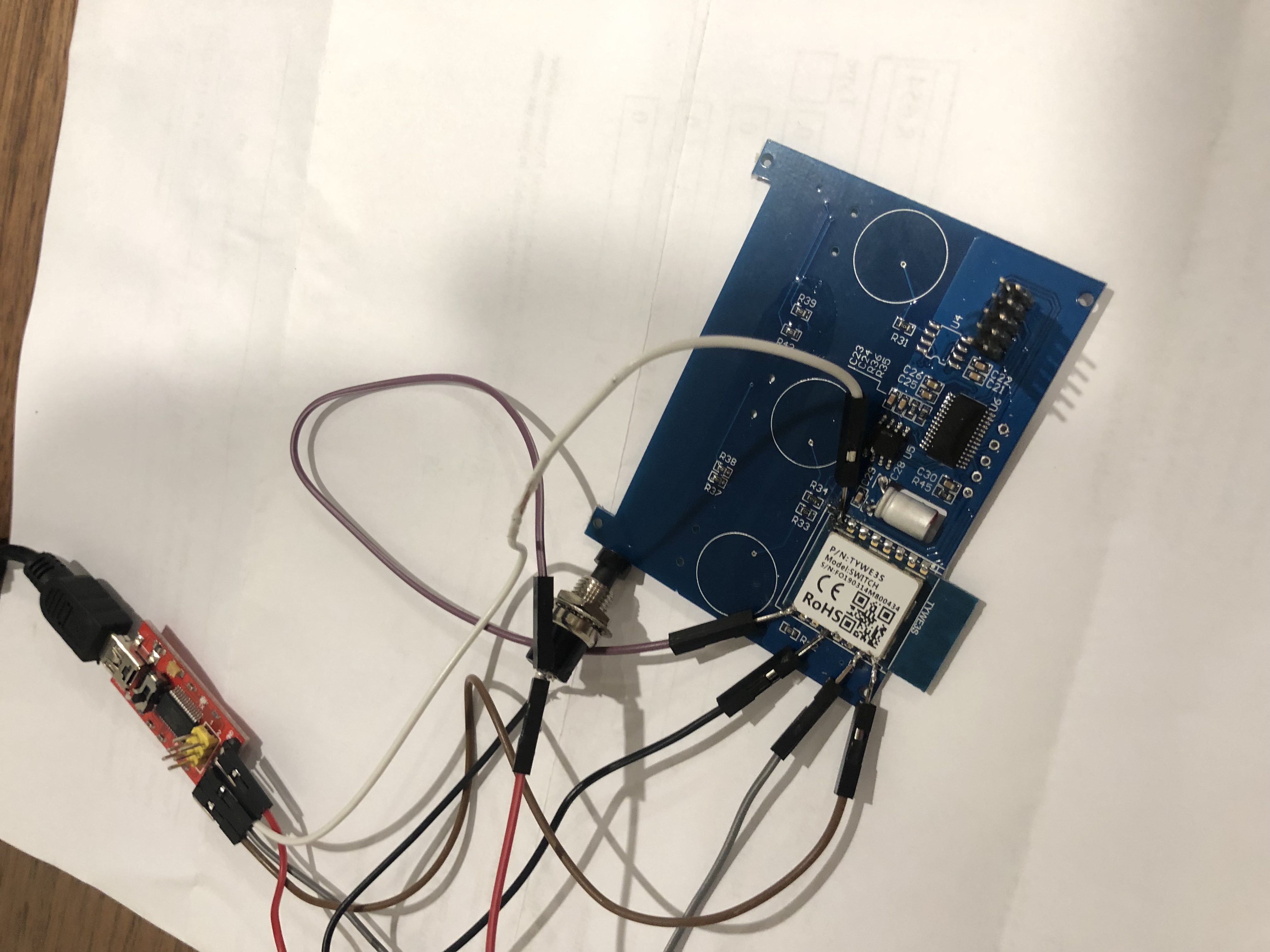
With the multi-meter, it doesn't look like the 4 contact holes are the standard programming pins as only the first one from the right and the third one connects to TYWE3S as 1st is VCC and third is GRND. While checking the CB on both sides, I believe the button is not connected to any of the TYWE3S pins other than the ground. I tried to follow its pins with the multimeter but i've got lost on those routes.
It sounds like the "wise" SmartLife that made this dimmer just added recently a very tricky
protection on hardware side not only on software one.... and that for just 12$ :))
I am adding the picture of the back of this board in a hope that will make more sense for you.
Honestly, I'm thinking this is a lost cause

meingraham
commented
5 years ago I wonder if the same issue is affecting you as with this device: https://github.com/arendst/Sonoff-Tasmota/wiki/ERC309-Kinetic-Switch
Here, the reset chip reset has to be grounded in order to flash the Tuya module. Alternatively, the Wi-Fi module has to be removed in order to flash it.
kozumin
commented
5 years ago I wonder if the same issue is affecting you as with this device: https://github.com/arendst/Sonoff-Tasmota/wiki/ERC309-Kinetic-Switch
Here, the reset chip reset has to be grounded in order to flash the Tuya module. Alternatively, the Wi-Fi module has to be removed in order to flash it.
:) Intriguing is the first part as I don't have to unsolder the spider out of the PCB. The question is how can I detect the reset pin on the reset chip?
kozumin
commented
5 years ago some findings

kozumin
commented
5 years ago Searching for this MCU chip code by GKOPY I found a new thread here: https://github.com/xoseperez/espurna/issues/1729 If that helps me to solve the problem I will post it here too. Fingers crossed!
kozumin
commented
5 years ago YES! the solution worked. The dimmer is now tasmotized by doing the followings:
 meingraham
commented
5 years ago
meingraham
commented
5 years ago @kozumin
Would you repay the kindness? Could you create a wiki page named RJWF-02A Dimmer and put the photos and information on how you were able to flash this device? Include also the template you configured for the device.
Thank you.
Mike
kozumin
commented
5 years ago Hi Mike,
I will do that as soon as I finish installing all 7.
fern-house.co.nz says thank you Mike :)

kozumin
commented
5 years ago the question is now how to integrate them to Hassio? any tutorial out there?
meingraham
commented
5 years ago https://github.com/arendst/Sonoff-Tasmota/wiki/Home-Assistant
A ton of Tasmota/HA tutorials on YouTube - DigiblurDIY, DrZzs, TheHookUp
There is also an HA Discord server
 tim-dcl
commented
5 years ago
tim-dcl
commented
5 years ago I found the following link https://forum.iobroker.net/topic/9886/tuya-jinvoo-unterputz-wandschalter/22 it looks like RST needs to be involved in order to get into flashing mode. Can anyone verify this?
meingraham
commented
5 years ago To clarify, this refers to the RST pin on the secondary MCU. This is separate from what is required to get the ESP into programming mode (e.g., its own RST pin).
BreBar07
commented
5 years ago No luck for me, LED's are also flashing so I guess is not in boot loader mode :(
It seems if I initiate the flashing soon after connecting to PC flashing starts but fails (8~12%). If i wait about 5 sec to start flashing its not found.
Any ideas?


tim-dcl
commented
5 years ago i dont see a connection on the RST in (the one on the 3v side opposite end). I had the same issue until i included that pin in the startup sequence.
On 7/26/2019 7:40 PM, BreBar07 wrote:
No luck for me, LED's are also flashing so I guess is not in boot loader mode :(
It seems if I initiate the flashing soon after connecting to PC flashing starts but fails (8~12%). If i wait about 5 sec to start flashing its not found.
Any ideas? Capture https://user-images.githubusercontent.com/53002554/61986412-59170b00-b052-11e9-9b82-391fe1f77e54.PNG IMG_0434 https://user-images.githubusercontent.com/53002554/61986426-69c78100-b052-11e9-965a-970be4a3951f.JPG IMG_0435 https://user-images.githubusercontent.com/53002554/61986438-78ae3380-b052-11e9-9211-bce6ca185159.JPG
— You are receiving this because you commented. Reply to this email directly, view it on GitHub https://github.com/arendst/Sonoff-Tasmota/issues/5377?email_source=notifications&email_token=ADFGVWNO3VUUHHQ6PFYTKALQBODQTA5CNFSM4G3HJJNKYY3PNVWWK3TUL52HS4DFVREXG43VMVBW63LNMVXHJKTDN5WW2ZLOORPWSZGOD256GCA#issuecomment-515629832, or mute the thread https://github.com/notifications/unsubscribe-auth/ADFGVWJFBVYPRHIHHWTNF73QBODQTANCNFSM4G3HJJNA.
BreBar07
commented
5 years ago Thanks @tim-dcl do you mean you grounded it? Because I've grounded it with GND and GPIO0 but board is not found during reflashing.
tim-dcl
commented
5 years ago yes. you need to ground RST, GPIO0 to start. after 3 seconds release RST. after another 3 seconds, release gpio0.
shoudl work after that. i used FlashESP8266.exe to flash new bin Tasmota_6.5.0(digiDIMv6).bin. This bin was made for this dimmer.
On 7/26/2019 8:36 PM, BreBar07 wrote:
Thanks @tim-dcl https://github.com/tim-dcl do you mean you grounded it?
— You are receiving this because you were mentioned. Reply to this email directly, view it on GitHub https://github.com/arendst/Sonoff-Tasmota/issues/5377?email_source=notifications&email_token=ADFGVWIQJXW6LBMVKPEGATDQBOJ77A5CNFSM4G3HJJNKYY3PNVWWK3TUL52HS4DFVREXG43VMVBW63LNMVXHJKTDN5WW2ZLOORPWSZGOD257ZFQ#issuecomment-515636374, or mute the thread https://github.com/notifications/unsubscribe-auth/ADFGVWLKJM5XJQGZKQJJ75TQBOJ77ANCNFSM4G3HJJNA.
tim-dcl
commented
5 years ago BreBar07
commented
5 years ago :( failed, still not detected.... I have tried different waiting periods still not detected :(
tim-dcl
commented
5 years ago is this the first device you have done with this method?
On 7/26/2019 11:33 PM, BreBar07 wrote:
:( failed, still not detected.... I have tried different waiting periods still not detected :(
— You are receiving this because you were mentioned. Reply to this email directly, view it on GitHub https://github.com/arendst/Sonoff-Tasmota/issues/5377?email_source=notifications&email_token=ADFGVWICO2FWZZ45Q6GMAATQBO62DA5CNFSM4G3HJJNKYY3PNVWWK3TUL52HS4DFVREXG43VMVBW63LNMVXHJKTDN5WW2ZLOORPWSZGOD26CVLQ#issuecomment-515648174, or mute the thread https://github.com/notifications/unsubscribe-auth/ADFGVWKZ7LZ5AR5HGGU44PTQBO62DANCNFSM4G3HJJNA.
BreBar07
commented
5 years ago Yes first device of this type. Still no luck over weekend doesn't seem to be in flashing mode. :( Anyone who helps or figures this out can claim any of 3x single wifi switches, 1x Xiaomi single wifi sw, 1x Xiaomi Zigbee hub.
I need to get these off Tuya cloud as the few second round trip really sucks for my automations, not to mention unlocking their true potential. Thanks in advance.
BreBar07
commented
5 years ago Anyone got any ideas?
meingraham
commented
5 years ago What is the device model that has that TYWE3S in it?
Not that it looks very easy to accomplish, but, are you able to detach the TYWE3S from the main PCB?
BreBar07
commented
5 years ago I haven't detached, as screen shot above it seems to be an ESP8266EX.
Do u think it's required to detach, not sure that will bring much benefit 😔
meingraham
commented
5 years ago @BreBar07
I guess I should confirm that you have tried to ground Reset on the ESP while booting and if that didn't do it, that you also tried grounding Reset on the MCU while going through the "normal" ESP programming mode boot.
There could be a connection to the main PCB that is keeping the Wi-Fi module from going into programming mode. There are several devices where the Reset pin is connected also to a secondary MCU and the MCU is keeping the ESP from booting into the desired mode. Some have found that the only way to flash the Tuya module was to detach it. It was mounted differently that this one so a bit easier.
In all of these cases I'm referring to Tuya modules that are ESP8266/ESP8285 based.
Mike
BreBar07
commented
4 years ago Thanks @meingraham, I've been a little quiet as we just had a little baby join us.
I've grounded both reset and gpio pins with no luck. I've got a little time over the coming week I'll try remove the chip and flash it (fingers crossed).
BreBar07
commented
4 years ago @meingraham Well I was excited so I got onto this faster than expected. Removing the 8266 I believe is almost impossible without destroying the board's so i decided to do some playing with grounding pins on the other MCU chip and success (I will add a more detailed description later, once next problem is solved).
Now I have Tasmota installed and I assumed that the configuration "Sonoff T1 1CH Module" and '2CH' would work but it seems not. Does anyone have any advise how to configure or is it just a trial and error exercise?
Basic Reflash gpio0 -> gnd tx -> rx rx -> tx vcc -> 3.3v gnd -> gnd rst -> gnd
mcu pin? -> gnd (upload picture later)
After a few seconds release rst from ground and device will flash!
I have a 3 gang touch switch with a TYWE3S. I am unable to flash tasmota on it. I'm pretty sure it's in boot mode when I ground GPIO0 and all 3 lights are red when I power it up. I have flashed 6 sonoffs using the same process. I tried reversing the Tx and Rx as well. I get an error "espcomm sync failed, espcomm open failed, espcomm upload mem failed"