 mikenivato
commented
4 years ago
mikenivato
commented
4 years ago Was wondering the same thing...
Closed klotzma closed 4 years ago
mikenivato
commented
4 years ago Was wondering the same thing...
 ascillato
commented
4 years ago
ascillato
commented
4 years ago Please, provide photos of the internal board.
 klotzma
commented
4 years ago
klotzma
commented
4 years ago 


 ascillato2
commented
4 years ago
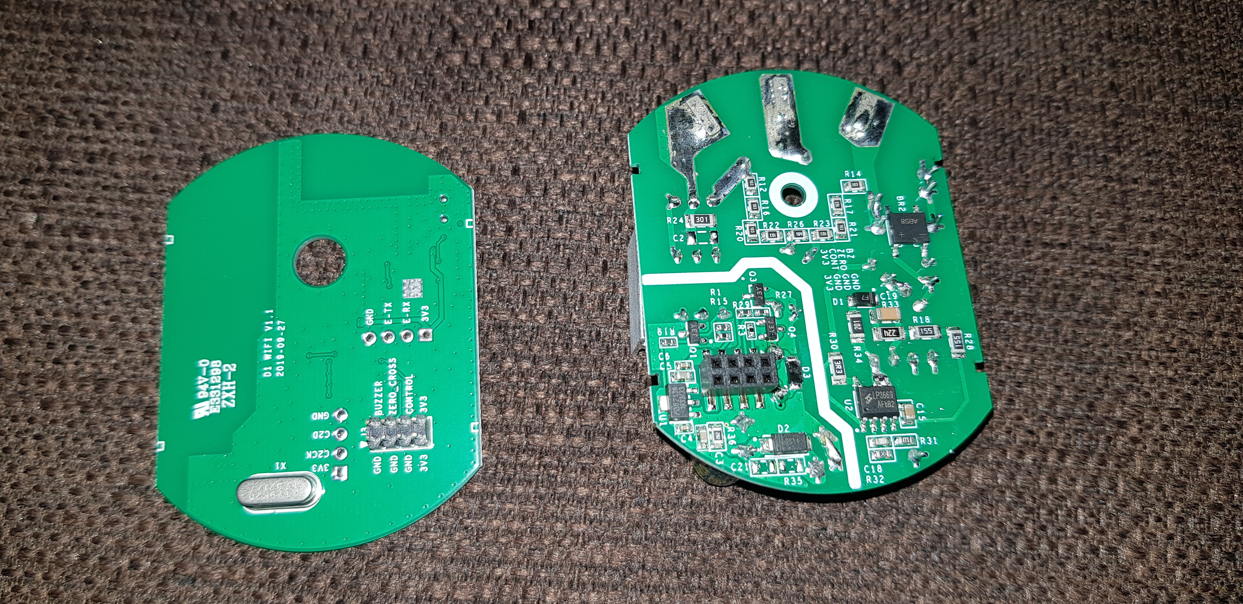
ascillato2
commented
4 years ago Thanks. Really good photos.
This device has an ESP8285 so Tasmota can be flashed but as it has also some extra circuitry, a reverse engineering is needed to make or adapt a driver for that.
 arendst
commented
4 years ago
arendst
commented
4 years ago I love the OTA switch
 digiblur
commented
4 years ago
digiblur
commented
4 years ago I have one flashed with Tasmota myself. I tried all the GPIO pins as relays and that doesn't seem to do anything. Pretty easy to flash and didn't even have to solder or mess with the stupid DIY mode. Pins were open and GPIO 0 is broken out to a pad for you to touch to ground while applying power.
 kugelkopf123
commented
4 years ago
kugelkopf123
commented
4 years ago I have one flashed with Tasmota myself. I tried all the GPIO pins as relays and that doesn't seem to do anything. Pretty easy to flash and didn't even have to solder or mess with the stupid DIY mode. Pins were open and GPIO 0 is broken out to a pad for you to touch to ground while applying power.
There is no relay on this board. It’s just a power mosfet. That mosfet controls the voltage for the high side output. Under the mosfet is an optocoppler that is linkt to the control pin of the header. So, I think there Must Be some kind of analog signal to control this coppler.
But I ask myself, for what is this Buzzer?
klotzma
commented
4 years ago I have one flashed with Tasmota myself. I tried all the GPIO pins as relays and that doesn't seem to do anything. Pretty easy to flash and didn't even have to solder or mess with the stupid DIY mode. Pins were open and GPIO 0 is broken out to a pad for you to touch to ground while applying power.
There is no relay on this board. It’s just a power mosfet. That mosfet controls the voltage for the high side output. Under the mosfet is an optocoppler that is linkt to the control pin of the header. So, I think there Must Be some kind of analog signal to control this coppler.
But I ask myself, for what is this Buzzer?
The dimmer can also RF 433Mhz. There is a remote control for the dimmer, the instruction manual says that if you connect the remote control to the dimmer, the dimmer beeps briefly.
digiblur
commented
4 years ago @kugelkopf123 yep, that's why I tried the relay pins to see if we needed to do PWM but alas no... thinking maybe some sort of serial signal to another chip but I haven't googled the other ones yet.
 robbz23
commented
4 years ago
robbz23
commented
4 years ago I have some better pictures posted here and here. I have traced Tx and Rx from the ESP chip through a 1k resistor and to the pads that are labeled the same close to the BB10. When I grounded them it stopped being able to dim. So I think you are right that it uses serial to tell the MCU how to dim. This is similar to what Tuya does. How can I monitor the serial lines so I can see what is being sent over them while I am dimming?
 sfromis
commented
4 years ago
sfromis
commented
4 years ago How can I monitor the serial lines so I can see what is being sent over them while I am dimming?
If it is plain old serial communication, one-way sniffing should work with just a normal USB/serial adapter (like also usable for flashing), and possibly experiment to find the right bit rate.
 thxthx0
commented
4 years ago
thxthx0
commented
4 years ago Hi, what about https://templates.blakadder.com/sonoff_D1.html ? seems to work simply with TRIAC and PWM...
but TRIAC = leading edge = 🤕
 Jeffrey-Wayers
commented
4 years ago
Jeffrey-Wayers
commented
4 years ago Hi, what about https://templates.blakadder.com/sonoff_D1.html ? seems to work simply with TRIAC and PWM...
but TRIAC = leading edge = 🤕
Does anyone know if this works? Not so experienced with templates so scared to try it before knowing if it works.
mikenivato
commented
4 years ago Any luck with this or outlook on it... I would help but don't know where to look.
Currently waiting to pull the trigger either on the Sonoff D1 or Shelly Dimmer
digiblur
commented
4 years ago That's a negative, I figured it wouldn't work as I tried a relay output on it and nothing. I tried this PWM template and nothing comes out of it.
 sandeep-ma
commented
4 years ago
sandeep-ma
commented
4 years ago Are you using an oscilloscope to test?
digiblur
commented
4 years ago Tried and true old school light bulb.
sandeep-ma
commented
4 years ago I feel that the high voltage board is the equivalent of this https://robotdyn.com/ac-light-dimmer-module-1-channel-3-3v-5v-logic-ac-50-60hz-220v-110v.html There is a lot of documentation from RobotDyn on how to use it with a generic microprocessor. The low voltage board probably supplies the PWM and ZCD, so here we are talking about high frequency digital pulses, maybe not as simple as a simple switch.
Here is lib for that module with esp code, should be very similar for D1 https://github.com/RobotDynOfficial/RBDDimmer
sandeep-ma
commented
4 years ago I confirmed that sending 3.3v to buzzer pin turns on a buzzer... cute.
I don't intend to flash it with hub based firmware as I prefer IOT mode without hub. But what I am struggling with is how to turn it on and off locally. I tried shorting each pin to 3.3v or ground, but only one pin (c2ck) turns it off when grounded and nothing turns it on. On the sonoff basic, I have been using this approach for hooking up capacitive touch sensors by sending ground pulse to the reset button. I do need a way to be able to physically turn these on and off, without remote. Really strange that they got rid of the reset button. Is there gpio that I could use as a reset button?
 cdntinker
commented
4 years ago
cdntinker
commented
4 years ago It's not gonna be a matter of figuring out which I/O does what. The ESP8285 talks to a second MCU (a Silicon Labs BB10) through the serial lines. The BB10 chip controls the high voltage board.
 Gravitate1
commented
4 years ago
Gravitate1
commented
4 years ago It seems odd that Sonoff would make the D1 so easy to flash a DIY firmware, but then make it difficult to actually control the dimmer from that firmware.
sfromis
commented
4 years ago It seems odd that Sonoff would make the D1 so easy to flash a DIY firmware
They did'nt. No DIY mode (which sucks anyway), they just did not go out of their way to make flashing hard. While it would have been nice of Itead to publish tinkering info, that is just not priority in a tiny market.
kugelkopf123
commented
4 years ago I dont see the Problem. Why nobody with this model put on a Serial Converter on this two Serial Lines and write down what happens if you Dim. The lines are also broken out. so no big deal imo.
Gravitate1
commented
4 years ago I would but I have already flashed mine and foolishly did not take a backup of the original firmware...
Gravitate1
commented
4 years ago It seems odd that Sonoff would make the D1 so easy to flash a DIY firmware
They did'nt. No DIY mode (which sucks anyway), they just did not go out of their way to make flashing hard. While it would have been nice of Itead to publish tinkering info, that is just not priority in a tiny market.
Have I not understood what DIY mode is? They included a hardware OTA switch. And they made it super modular, with numerous break outs. It certainly seems like they deliberately made it easy for DIY... (until we come to actually controlling the dimmer.)
sfromis
commented
4 years ago Have I not understood what DIY mode is?
Sonoff D1 is not listed among devices with DIY mode.
Some breakouts is pretty common in ESP8266 devices, but if easy flashing was intended, they'd have broken out gpio0, which they do not even do in "classic" Sonoff devices like the Basic. While it is not hard to find, it is just not a preplanned use case. Definitely not "easy for DIY".
cdntinker
commented
4 years ago No DIY mode (which sucks anyway)
No DIY mode??? I'm sitting here looking directly at the box. Says "Sonoff DIY D1". Also, it has a switch labelled "OTA" and a hole in the front cover to reach the switch. Pretty sure it has DIY mode... :P
cdntinker
commented
4 years ago Sonoff D1 is not listed among devices with DIY mode.
That link shows that the information is 6 month old. The D1 dimmer is a new device... Is it possible the list is out of date???
sfromis
commented
4 years ago Anything intended for self-mount is called "DIY", also very much without without a dedicated "DIY mode". The Sonoff Micro is listed, while it is extremely tinker-unfriendly.
sandeep-ma
commented
4 years ago It seems that it will support rest api rather than flashing, like mini. It could be that it is not yet implemented and will come with a firmware update. They replaced jumper in mini with a switch https://github.com/itead/Sonoff_Devices_DIY_Tools/blob/master/other/SONOFF%20DIY%20MODE%20Protocol%20Doc%20v1.4.md
digiblur
commented
4 years ago Mini is definitely not tinker friendly in my book. With so many recent Sonoff products missing the mark lately this one might not be worth the effort. I do have backup of the firmware and will see what I can do on reverse engineering the serial stuff next week.
sandeep-ma
commented
4 years ago It is running firmware 3.4.0 and REST API is supported from 3.3.0 onwards. I don't get it why you people are so bent on flashing firmware. Just switch to OTA mode and connect to your hub using the API. You will need to program the hub rather than write firmware... sounds a lot more scientific to me
digiblur
commented
4 years ago Local control and open source is the only way.
sfromis
commented
4 years ago The circuitous inclusion of 3rd party flashing of firmware in "DIY mode" gave the impression of Itead at least understanding the relevance of alternate firmware, but it is not something included in their two newest devices. It may or may not have been on the table while designing the D1, but it is just not part of the current product.
Gravitate1
commented
4 years ago Mini is definitely not tinker friendly in my book. With so many recent Sonoff products missing the mark lately this one might not be worth the effort. I do have backup of the firmware and will see what I can do on reverse engineering the serial stuff next week.
Do you think you could share that backup of the original firmware with me and I will see if I can investigate the serial comms? I'm pretty new to this so probably won't be successful but wouldn't mind giving it a go.
sfromis
commented
4 years ago I've not got an overview of all jurisdictions, but technically it would not be legal for me as a non-professional to install a D1 in my walls. If I were a lawyer for Itead, I'd probably point at legal risks of explicitly designing products for professional install to be modified by enterprising amateurs.
While tinkerers can of course "break into" lots of products, they're clearly taking on the responsibility for faults when doing this. If the manufacturer instructs about how to modify, I imagine that this could affect the outcome of a court case.
sandeep-ma
commented
4 years ago I've not got an overview of all jurisdictions, but technically it would not be legal for me as a non-professional to install a D1 in my walls. If I were a lawyer for Itead, I'd probably point at legal risks of explicitly designing products for professional install to be modified by enterprising amateurs.
While tinkerers can of course "break into" lots of products, they're clearly taking on the responsibility for faults when doing this. If the manufacturer instructs about how to modify, I imagine that this could affect the outcome of a court case.
Agreed, they are cleaning up the mess so that they can offer it to the masses. That is why Mini and D1 have the control API. In any case, they never supported flashing, it was invented by hackers.
But I would have preferred if they supported ewelink and api side by side rather than by a hardware switch.
sfromis
commented
4 years ago In any case, they never supported flashing
Well, actually ... The "DIY mode" does support unlocking and OTA flashing of new firmware, in contrast to no official flashing support being available for older devices which are unintentionally "friendly" to serial flashing.
Gravitate1
commented
4 years ago I also agree... however, as unwise as it would be for them to provide "instruction", there would be nothing preventing them simply publishing the technical details under another context (which would be a big help to us "tinkerers").
sandeep-ma
commented
4 years ago They could argue in court that it is supported for flashing OEM firmware and not tasmota :)
sfromis
commented
4 years ago It might be possible to find a spec sheet for the chip which is controlling the high power side, without this having to be published by Itead.
Gravitate1
commented
4 years ago It is a BB10F8G - I think that the datasheets can be found here: https://www.silabs.com/mcu/8-bit/efm8-busy-bee/device.efm8bb10f8g-qfn20
sandeep-ma
commented
4 years ago There are some interesting documents here in the FCC cert for D1, but nothing useful https://fcc.report/FCC-ID/2APN5D1 https://fccid.io/2APN5D1 Which chip are you talking about? Can you point it out in the picture?
sandeep-ma
commented
4 years ago I bet that the other chip is not doing anything important, just providing the PWM pulses to align with the ZCD, based on an analog output from the ESP. You just need to do the analog part, which would be a voltage between 0 and 3.3V from the analog IO on the ESP
Gravitate1
commented
4 years ago I dont think so... you can trace the Tx & Rx lines from the ESP to the BB10... so looks very much like a serial connection... I will upload an image shortly.
Gravitate1
commented
4 years ago 
You can see the ESP on the right. The BB10 on the left. Linked via the TX and RX lines.
digiblur
commented
4 years ago Here's the backup..
sonoff_d1_backup.zip
Gravitate1
commented
4 years ago Thanks. However I have just read that the original firmware is locked to each device. So not sure if it will work. Will let you know.
robbz23
commented
4 years ago I have been messing with a bit and can confirm that dimming from the app uses the serial between the bb10 and esp. If I ground the serial lines then dimming stops working. I tried to hook up a serial converter but I can't get anything to show up on the terminal yet. I am guessing baud should be either 9600 or 115200? I wish I had a logic analyzer.
 leifclaesson
commented
4 years ago
leifclaesson
commented
4 years ago I just received two Sonoff D1 units in the mail today. I haven't powered them up yet but found this thread by google.
Dimming through REST API sounds pretty good but I'm anticipating needing to write custom firmware in order to use the 433 MHz receiver for my own purposes. The Sonoff D1 looks like it could be a convenient form factor for adding 433 MHz receiver to each room, in order to use wall mounted remotes to control different unrelated things -- if possible.
Did anyone try the 433 Mhz receiver yet?
Have you looked for this feature in other issues and in the docs?
Yes
Is your feature request related to a problem? Please describe.
A clear and concise description of what the problem is.
I cant't find a Template for this Device.
Describe the solution you'd like
A clear and concise description of what you want to happen.
Sonoff has released a new dimmer, the Sonoff D1 dimmer. Is Tasmota compatible with this dimmer, if not, is it possible to add it?
Thanks Describe alternatives you've considered

A clear and concise description of any alternative solutions or features you've considered. Only Support. Additional context
Add any other context or screenshots about the feature request here.
(Please, remember to close the issue when the problem has been addressed)