 gisep
commented
5 years ago
gisep
commented
5 years ago IDEA!
could be integrated attaching the relay to one of the limit switch pins. The Tmax can be set directly on that circuit without modifying the firmware.
Closed gisep closed 4 years ago
gisep
commented
5 years ago IDEA!
could be integrated attaching the relay to one of the limit switch pins. The Tmax can be set directly on that circuit without modifying the firmware.
 arkypita
commented
5 years ago
arkypita
commented
5 years ago You can wire it to feed-hold and cycle-start. https://github.com/gnea/grbl/wiki/Connecting-Grbl
However I think that a proper cooling and a safe current driving (ie set laser driver to provide 20-25% less then max diode current) should prevent laser overheating.
gisep
commented
5 years ago Thank you Arkypita! I think that could be better than the limit switch pins, to avoid the hard-reset and control an automatized pause-resume. But how can these two pins be controlled by a relay? They maybe need some simple added circuit.
As you said, the cooling and the current regulations are the best ways to prevent the overheating. That will be an addictive precaution I want to take just because I fried the first diode and want to better control the next; visualizing the temperature I will understand how much it heats, depending on the time-usage and on the environmental temperature.
 Focus3
commented
5 years ago
Focus3
commented
5 years ago Hi guys,
just wanted to share how I solved my Laser cooling. I used a peltier element and a peltier controller. The cost is 2 $ for Peltier element and around 24 $ for the controller.
You can find the controller on ebay by searching for "WH7016K". And the peltier element I used is a 30x30 mm because it fits perfectly on the housing.


On the picture above you can se that you mount the peltier element on the housing using thermal paste. You need to add an Aluminum block and you can use the fan from the laser control circuit to cool the block (i connected the fan on permanent 12V).
To mount the temperature sensor, you can use the exiting thread that was used to mount the fan. You just need to drill a 4 mm hole, then press the sensor in it.
The controller lets you set the temperature to which it should be cooled.
Hope it helps.
gisep
commented
5 years ago What diode do you use? Peltier cell could be a great system but i've read it's poor in efficiency. Is that heatsink dissipating enough? Usually i see biiiig cooling systems..
Some time ago i was thinking to build a Peltier cooling system, but talking with Alexdam (we're now building together two lasercutters) he suggested that could be useless or even dangerous, if not well designed. So the best consideration we could take was to start to know our real needings.
It could be interesting to have your feedback about its trend, pros and contros (for example what about thermal asimmetry and deformations?)
A last question: i don't understand well your laser's support. Is that engine controlling the focus by rotating the lens??
Focus3
commented
5 years ago I used a 2.5W blue 445nm Diode.
To tell you the truth i also was not sure about the peltier unit, but wanted to test it and get it ready cause i would love to change the laser to a NUBM 44 7W if i get the change.
I think it's a reasonably efficient cooling sistem if used properly. What i mean by that is that, when the peltier is active, one side is cold and the other gets warm/hot relatively fast. When installing I made sure to polish all the cooling surfaces, use thermal paste properly (even thin layers) and used a 12V fan permanently active.
I set the controller to 20 Degrees celsius and done some tests. Measured temperature with a IR thermometer and I was pleased to see that the laser temperature was the same as set temperature after hours of engraving.
The laser has a 12V dc motor with mini gearbox inside. The dc motor is controlled with a 5V signal (so the motor runs slower) with two relays. I used a two position switch to activate it. It has become a really practical feature when preparing a job.
I hope this helped.
arkypita
commented
5 years ago If you are a maker you can build a simple temperature monitoring using a TO92 temperature sensor like DS18B20 or TMP36 / LM335 and an arduino nano or even better with digispark attiny85 for read the sensor.
Make a small hole in the heat sink, as close as possible to where the laser is mounted, and place sensor into this hole. Wire it up to an analog input (or digital for DS18B20) of your microcontroller and write a simple program that activates feed-hold when a temperature threshold is exceeded and resume job work when temerature fall below a lower threshold like in schmitt trigger.
Unlikely i think that this feature cannot be implemented in a customized grbl firmware because grbl code use all of its arduino resource, but i can be wrong. If there is a little of space, maybe a well optimized code can fit it.
arkypita
commented
5 years ago My laser is 2W M140 blue diode like this one from jtechphotonics. However mine is from dtrlasershop.
It is know that this diode can support up to 1.8A but as you can see jtech raccomand to use it at 1A (about 1.3W of optical power) to preserve its lifetime. My setup is 1.5A and cooling is done with a simple aluminium heatsink and radial fan. I never noticed excessive warming of the heatsink.
arkypita
commented
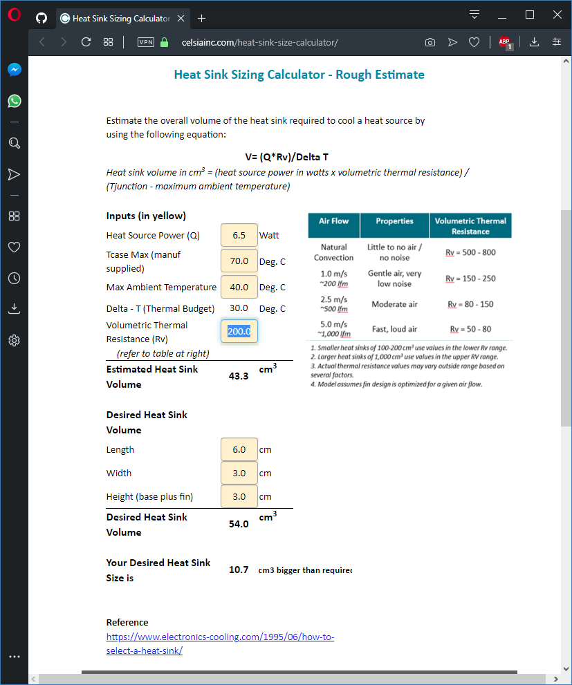
5 years ago About thermal heatsink design, just as example:
A diode that absorb 1.7A at about 5V (8.5W of electrical power) to produce an optical power of 2W is wasting 6.5W of power (not all the electrical power is converted in optical power; it is normal and it is called efficiency).
This waste of power is heat, and it should be drained out or the diode will burn.
I am not an engineer of thermal design but based on some tools I have found on web it seems that a 3x3x6 cm heatsink with a gentle air flow can be sufficient.
gisep
commented
5 years ago @Focus3 Thanks for your sharing experience, this system will be even more amazing when applied to the NUBM44 (the same diode I bought and waiting for), when the dissipation becomes more important in terms of quantity.
@arkypita Did you cut that junction frames with that laser diode??
I don't really know the functionment of the feed/hold command (is it already included in the firmware, no?) but if a relay could be enough to control it, the sensor i linked in the second post has already got the external brain to visualize and control Tmax and treshold. If the feed/hold has to be programmed in the firmware, i think that a few strings will be enough using that external brain. The only difficulty would be the prior study but my optimistic ignorance let me think that's possible.
The site to calculate the heatsink dimensions is amazing.
arkypita
commented
5 years ago @Focus3 Thanks for your sharing experience, this system will be even more amazing when applied to the NUBM44 (the same diode I bought and waiting for), when the dissipation becomes more important in terms of quantity.
Yes, but i think that the heatsink usually sold with this kind of diode should be ok.

@arkypita Did you cut that junction frames with that laser diode??
Yes, my first frame was build using drawers guides. With that frame i cut supports for steel rods, linear bearings and more. http://lasergrbl.com/it/my-own-engraver/
I don't really know the functionment of the feed/hold command (is it already included in the firmware, no?) but if a relay could be enough to control it, the sensor i linked in the second post has already got the external brain to visualize and control Tmax and treshold.
Feed hold act the same as if you press the button with the "red hand" on lower right of LaserGRBL interface. In grbl v1.1 it stops any movement and power down the laser, without loosing position and without discharging command buffers. Job resume restart from where it stop.
There are two pins on arduino that can be used as input pin for feed/hold and resume, so you can wire up a buttons, or better an "intelligent" temperature control that could pause the job when diode overheat: https://github.com/grbl/grbl/wiki/Connecting-Grbl
The site to calculate the heatsink dimensions is amazing.
Yes, but i am not sure about its reliability. There are a lot of variables when designing thermal heatsink that this module does not take in care about.
I think it is useful just to estimate, better than nothing.
gisep
commented
5 years ago [HEATSINK]
Yes, but i am not sure about its reliability. [...] I think it is useful just to estimate, better than nothing.
Yeah, for example the ambiental temperature will directly affect the efficiency.
[2W LASER]
With that frame i cut supports for steel rods, linear bearings and more.
If with your 2W laser you can cut 3mm wood, with a true 15W laser you should cut at leat 6-8mm wood! And these are not really true. Just for information... how many passages with which velocity do you need to cut that wood?
[FEED HOLD] About the "feed hold" it's ok and will be easy to upgrade. More difficult with the "temperature controller extension" with only a relay (this) is to do an automatized hold/resume control: the simplest solution will be to "feed hold" with the controller extension and then manually "resume". Or is there a way to transform the A1 "feed hold" into a reversible "push button"?
arkypita
commented
5 years ago Just for information... how many passages with which velocity do you need to cut that wood?
With my laser I can cut up to 5 mm plywood in 6-10 passages at 100 mm/min. Number of passages depends by plywood quality and wood essence.
[FEED HOLD]
Grbl hardware pin for feed/hold and job resume are designed to be connected to pushbuttons, so I think they react to down-front when you close them to ground with pushbutton as they are kept at high level by internal pull-up resistor.
For the usage with a relay "temperature controller" like the one you link, you should at least build a small circuit that transform on-off signals from relay to pulses for hold-resume input (front detector). A circuit with some transistor and capacitor or a pair of 555 timer IC should do the job, but you need electronic skill to project and build it.
In my opinion the temperature controller solution you linked is not a good one, because only work as "thermal power cut off" for the laser but does not stop motor or inform grbl to stop processing command. Moreover for what i have found about it it does not allow you to program hysteresis, i mean two different thresholds: one to stop and a different (lower) threshold to resume.
IMHO the best temperature control that you can build is done with arduino nano or digispark attiny85 and TO92 temperature sensor like DS18B20 or TMP36 / LM335.
gisep
commented
5 years ago With my laser I can cut up to 5 mm plywood in 6-10 passages at 100 mm/min.
That's really good and a good comparison to "powerful" chinese diodes.
[FEED HOLD]
it does not allow you to program hysteresis
I'm not sure but i think that could be the P1 function (Return difference).
I think I'll connect it to the "feed hold" pin and manually resume until learning how to program arduino nano to automatize the process. Thanks for all the suggestions!
Hi, I'm redesigning my laser cutter and was thinking that a thermometer (temperature sensor) could be a nice add to control the diode temperature and pause the work if it becomes too hot.
That would be a great resource to avoid the diode from burning and save resources (and money).
Do you think it would be easy? How can be done? Maybe it needs firmware modifies, for pausing the job with a counter if the temperature signal overpasses the limit..
I was thinking to do it (in emergency) with an external controller with a relay that turns off the laser driver (and/or the arduino), like a veryhard limit, in order not to lose the diode integrity, nor its coordinates.
What do you think?