 aromring
commented
4 years ago
aromring
commented
4 years ago Hi Andrii, Yes, I will be glad to help. Please open the README file here https://github.com/aromring/MAX30102_by_RF/blob/master/README.md scroll down to HOW TO REPORT BUGS section and follow instructions therein.
 akuznets0v
 asemchenko
 supersuperfranz
 jointothedarkside
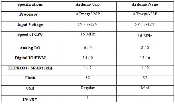
Hi!
I have used this library with Arduino Nano, and it looks like SpO2 is calculated right but heart-rate value is always 83 and does not changes. Can you help me to understand what is going wrong and how to deal with it, please?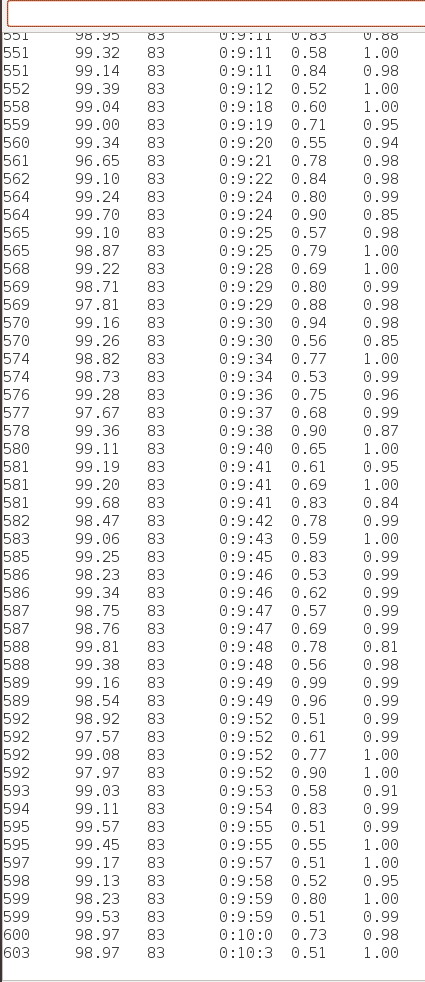
I am using the sketch below (there is no any changes, I've just commented some features (DEBUG, ADALOGGER, SAVE_ROW_DATA)