 coelner
commented
1 year ago
coelner
commented
1 year ago https://github.com/atc1441/ZBS_Flasher/blob/main/ESP32_Flasher/platformio.ini
[env:lolin32_lite]
platform = espressif32@5.0.0
board = lolin32_lite
framework = arduino
#upload_port = COM17
upload_speed = 921600
#monitor_port = COM17
monitor_speed = 115200
build_flags =
    -D LED=22
    -D ZBS_SS=23
    -D ZBS_CLK=18
    -D ZBS_MoSi=5
    -D ZBS_MiSo=17
    -D ZBS_Reset=19
    # do not connect directly to a GPIO only trough some kind of Mosfet or switch!
    -D ZBS_POWER=16
    # Used to read UART data from the firmware running on the ZBS, not needed at all
    -D ZBS_RXD=4
    -D ZBS_TXD=2
    -D ZBS_SPI_BUS=VSPI
However it is a little bit confusing in the README, that it is named ESP32. As you can see here: https://mischianti.org/wp-content/uploads/2021/07/ESP32-WeMos-LOLIN32-Lite-pinout-mischianti.png or https://1.bp.blogspot.com/-mG0x8f0BKTA/WmiYamp9XdI/AAAAAAAAg5Y/N_P7plcbtmU-15JKqURYqE_yjt98AUdxwCLcBGAs/s1600/Lolin32_pinout03.png
the pins are labeled after the GPIO number. Now it depends (AFAIK), which SAOLA pcb version you have. the versin 1.2 atleast do have the labeled pcb pins likewise to the GPIO numbers.
However GPIO23 is not available, GPIO 18 is connected to the onboard RGB LED. Those need to be changed.
//Edit: https://docs.espressif.com/projects/arduino-esp32/en/latest/api/spi.html
  //initialise vspi with default pins
  //SCLK = 18, MISO = 19, MOSI = 23, SS = 5
completely unverified:
[env:esp32-s2-saola-1]
platform = espressif32
board = esp32-s2-saola-1
framework = arduino
#upload_port = COM17
upload_speed = 921600
#monitor_port = COM17
monitor_speed = 115200
build_flags =
    -D LED=18
    -D ZBS_SS=34
    -D ZBS_CLK=36
    -D ZBS_MoSi=35
    -D ZBS_MiSo=37
    -D ZBS_Reset=19
    # do not connect directly to a GPIO only trough some kind of Mosfet or switch!
    -D ZBS_POWER=16
    # Used to read UART data from the firmware running on the ZBS, not needed at all
    -D ZBS_RXD=4
    -D ZBS_TXD=2
    -D ZBS_SPI_BUS=HSPI
masterX244
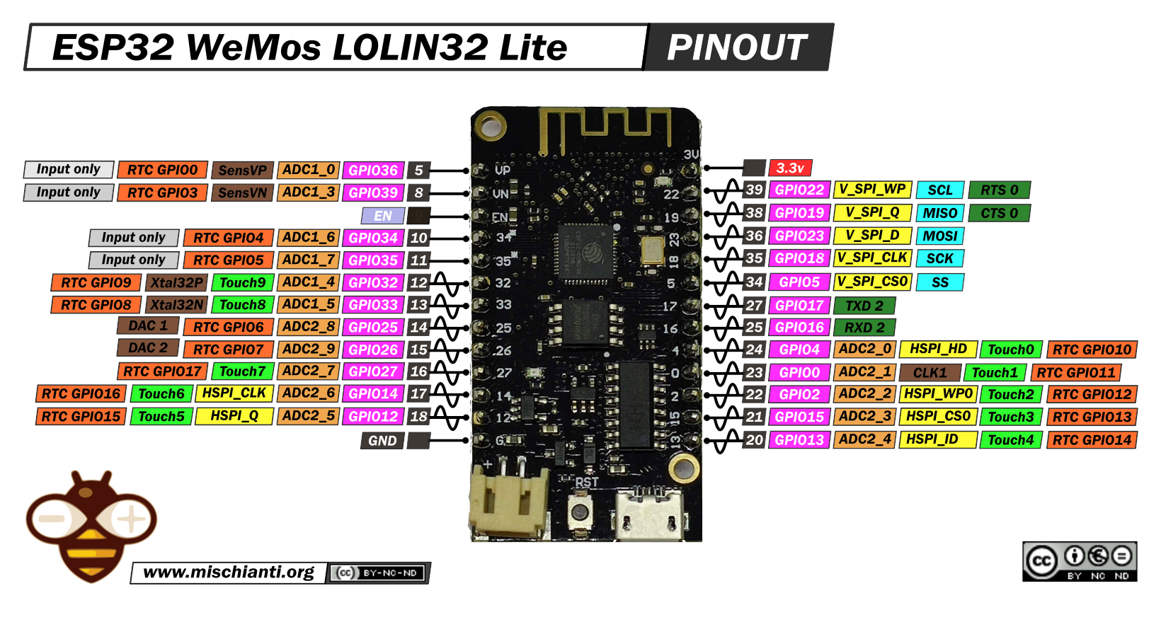
What pinout and changes are needed to use that board for flashing? Somehow the PlatformIO docs don't give a hint on how the Pin numbers map to the physical pins