basilfx / TRADFRI-Hacking

Hacking IKEA TRÅDFRI products, such as light bulbs, window blinds and other accessories.
631 stars 62 forks source link

Antenna of breakoutboard ON breakoutboard #11

Open oliv3r opened 6 years ago

oliv3r commented 6 years ago

Looking at the latest 3D rendering on the breakout board for the ZLL module, I notice the antenna is sitting ontop of the PCB. Would it not be more helpfull to move the antenna offboard, as is done with the led drivers? (e.g. have it stick out/no PCB underneath). The only real blockage would be the reset button which in turn could move down a little bit between the pin-headers or to the bottom left where the led also lives.

Further more, would it be a good idea to put through-hole pads underneath the ZLL module? E.g. that way we can either solder the module directly onto the carrier board, or solder pinheaders onto the ZLL module and headers onto the carrier board to make it swapable (or even put pins on the carrier board and 'squeeze' the ZLL module temporarily in between.

basilfx commented 6 years ago

I removed the copper fill below the antenna. I'm quite certain that it will affect performance, but since the ZLL module is also tightly soldered into a light bulb, I don't think it will affect performance that much (I don't have any numbers though).
oliv3r commented 6 years ago

why not have the antenna stick out however? All the modules from IKEA also do this from images I have seen. Granted, performance is not important at all herein.

darconeous commented 6 years ago

Copper fill below the antenna would have killed the performance. It was a good idea to remove it.

It's not clear how much effect having the antenna against the bare PCB would have. It would likely be minimal, but not zero. For a break-out board intended for testing purposes, I think it is more than sufficient.

Then again, I don't think these antennas are tuned with any great precision. I've noticed a very large variance of sensitivity across the handful of devices I have purchased.

I'm curious though why you are going for this sort of design with the break-out board. Wouldn't it be nicer to have a board which you could just plug into a breadboard? You could still keep the debug headers...

darconeous commented 6 years ago

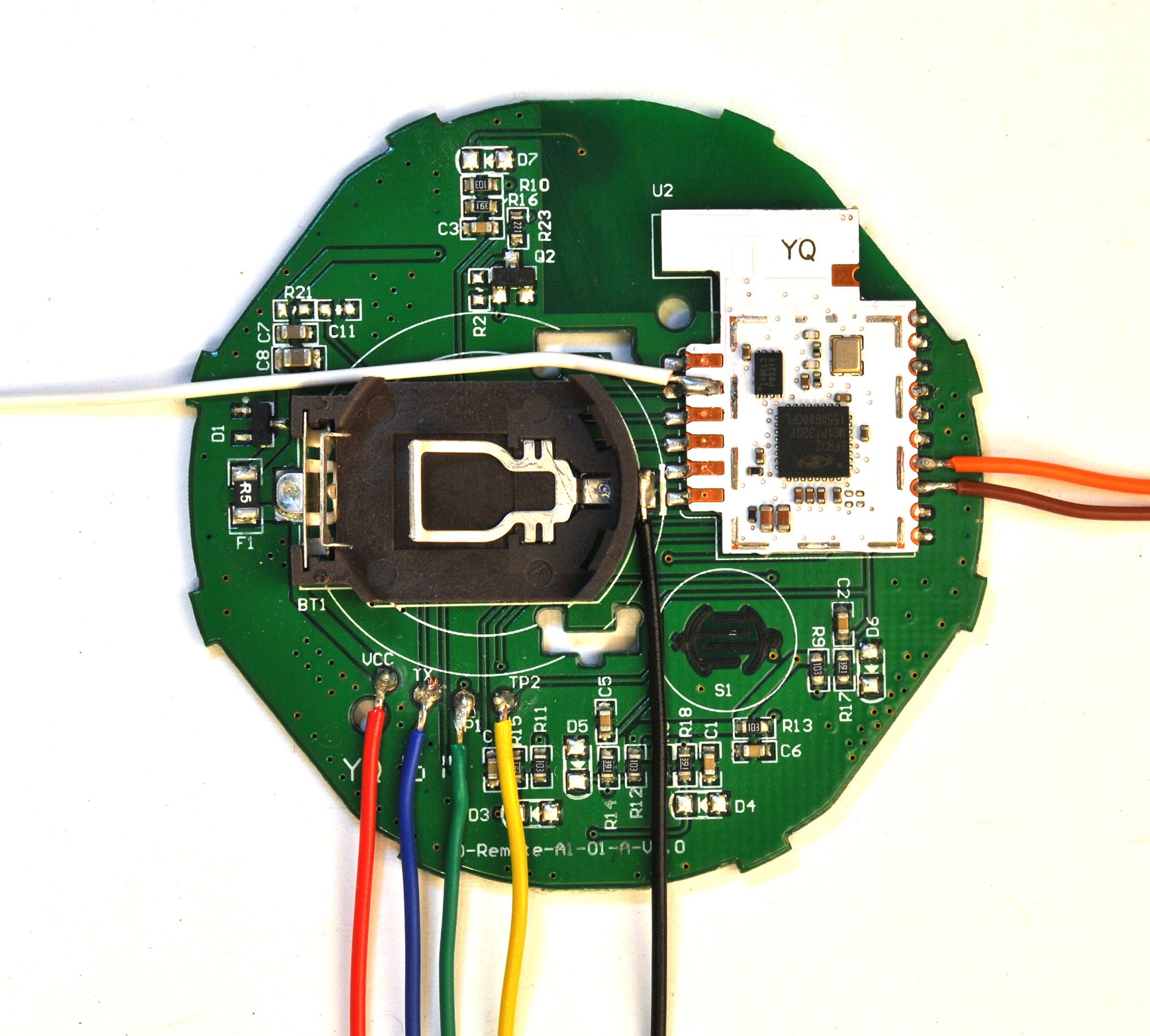
Have a look at the copper keep-out zone from the remote:

TRÅDFRI Remote Board

It's much larger than your keep-out zone.

oliv3r commented 6 years ago

I was thinking something like image was my thought :)

as for the pinheaders I think having it breadboardable/pluginable just depends on where you solder the pins, no?

P.S. Bas, what version of KiCad did you use, as I can't open it on Debian stretch nor on Fedora 28.

darconeous commented 6 years ago

as for the pinheaders I think having it breadboardable/pluginable just depends on where you solder the pins, no?

The more narrow the board, the better it will work with a breadboard.

oliv3r commented 6 years ago

actually, we can also find this in the FCC submitted manual: image and image