bdurbrow / grbl-Mega

An open source, embedded, high performance g-code-parser and CNC milling controller written in optimized C that will run on an Arduino Mega2560
https://github.com/gnea/grbl/wiki
MIT License
35 stars 8 forks source link

Connecting a Chinese spindle with an inverter. #4

Open qulet opened 5 years ago

qulet commented 5 years ago

Can anyone on "Wiki" describe step by step how to connect and properly control the RPM via PWM-DAC 0-10V. Chinese spindle with inverter? So far, I've done it with the vfdPlugin-1.7.1 plugin in Mach3. I can't do this at GRBL   connect and configure properly ... Please help!

Saur0o0n commented 5 years ago

Atmega/Arduino logic is 0-5V - so you can't directly control PWM driven spindle that expects 0-10V. That's why I was looking for 0-5V controller for my brushless 500W spindle. You need to create some additional translator 0-5V -> 0-10V. Example is here https://www.youtube.com/watch?v=VoeUr6CL9WA - sometime ago I even asked the question in comments about it.

qulet commented 5 years ago

Saur0o0n The link shows the control of the BLDC motor. I asked about inverter control, where the rotational speed is proportional to the direct voltage from PWM conwerter to DAC 0V to 10V.....

bdurbrow commented 5 years ago

Two options, depending on the exact hardware you have:

1: Have the grbl system output 0 to 5 volts pwm, and tell the inverter that it's maximum speed is twice what you actually want. That way, when grbl is outputing full speed (5 volts) the inverter will run at your actual desired speed.

2: Amplify the 0 to 5 volt pwm output to 0 to 10 volts... the easiest way to do this is with an op-amp.

For what it's worth, I've just received a batch of PCBs that (among other things) has an op-amp circuit on board for doing just this.

The relevant schematic looks kind-of like this:

PWM amplifier

The potentiometer was used (instead of two fixed resistors) so that the output level could be adjusted for different requirements (on the board in question, it's a 10k 10-turn 3296W trimmer).

Saur0o0n commented 5 years ago

Saur0o0n The link shows the control of the BLDC motor. I asked about inverter control, where the rotational speed is proportional to the direct voltage from PWM conwerter to DAC 0V to 10V.....

It's completely not important that this is BLDC - this was an example how to change voltage levels.

qulet commented 5 years ago

Saur0o0n ; Bdurbrown

Thank you very much for the hints, I will try to connect the inverter according to the given tips.

bdurbrow commented 5 years ago

I just realized something... I'm in the same boat! One of my machines (that's in pieces at the moment, but...) has a spindle that takes 0-10v, and I want to use the RAMPS card for it because the steppers are comparatively small.

So, I'm going to whip up a small PCB with that opamp circuit on it, and include it in my next batch of boards to send to China. I'm guessing it might take me a week - or if I get unlucky, two weeks - from now to get the batch ready for them; and then another two weeks for them to make the boards and send them back to me here in California.

Prototype PCBs usually come in 5 or 10 packs; and I'm going to order 10.... so I will have some left over. If anybody wants one, let me know here, and I'll see about setting up an eBay listing for it (I'll only charge actual material expenses + actual shipping).

Alternatively, I will also post the gerbers for the opamp module to github, so anybody can have the PCB made on their own.

Saur0o0n commented 5 years ago

Isn't that a bit overkill to prepare dedicated PCB for 4 components? (I mean sending, waiting etc) - I recently started milling my pcb on CNC - it's ok, definitely lacks finesse of silk and coating but works :)

bdurbrow commented 5 years ago

There's no kill like overkill! 😜

I've already got several PCBs that I need to send out... and it didn't take long to cook this one up. The machine it's for is in pieces, and won't be put back together before the batch of PCBs get here, so it's not impinging on my progress. With the price of prototype PCBs being so low these days, given my situation it's really a no-brainer. I'm going to just include it in the batch.

However, that doesn't mean that anybody else should necessarily go this route; or go this route first. It's entirely reasonable to put the circuit together on perfboard... and then either just keep what you have; or in a month or whenever, replace it with something a little nicer.

RAMPS Adapter PCB

Saur0o0n commented 5 years ago

Looks nice :) - What for is Analog output? And what are C3 values?

bdurbrow commented 5 years ago

PWM In connects to the Arduino; Analog Out connects to your spindle's VFD. You can scale the output by adjusting the 10-turn trimmer pots; in principal you could go to as high as your opamp can output. Practically, however, I figure most applications will need 0-10v output...

Values for Rpwm and C3 may vary depending on your PWM frequency as set in cpu_map.h - lower frequency's will require bigger values to get good smoothing behavior - but I'm going to use 4.7K and 10uf, because I have those on hand from the other breakout boards.

Hmm... I think I'll add some extra ground header pins, so you can disable an unused channel easily (the LM358 is a dual channel chip, so it's a dual channel board).

Saur0o0n commented 5 years ago

Analog Out connects to your spindle's VFD.

Oh.. I did not looked too closely before - sorry :) I thought that Out1/Out2 are VFD - and this are for potentiometers. Analog is for actual output.

Saur0o0n commented 5 years ago

Perhaps, if you already are preparing PCB - you could use this http://www.ti.com/lit/ds/symlink/cd40109b-q1.pdf - CMOS QUAD LOW-TO-HIGH VOLTAGE SHIFTER. It's quite similar to TXS0108E used for voltage shifting in range 1,2-3,6V to 1,65-5,5V - but I haven't found ready to use/buy board with it.

bdurbrow commented 5 years ago

Um... OK... can you be a bit more specific? What, exactly, do want it to do? (this would determine how I route the traces & otherwise configure the chip).

Saur0o0n commented 5 years ago

I've looked at this - because I'm also writing right now PID programmer for kiln - to translate 3.3v logic at 5V. TXS0108E 
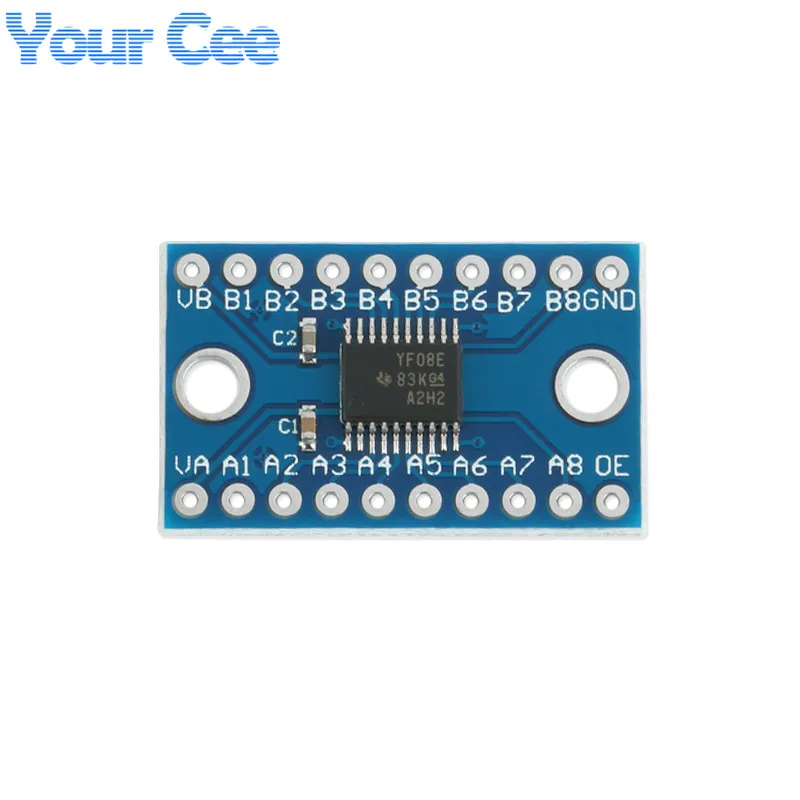
It's based on TXS0108E - all in one chip solution for 8 paths. This is just this chip, two caps and that's it. Then I've looked for something similar for 10V - and I haven't found (to buy). But there is, if I'm not mistaken, similar chip with higher voltage - this is the one I've mentioned before CD40109B-Q1. This is just proposition, perhaps better, perhaps not - just something to consider if you wish.

bdurbrow commented 5 years ago

Well, if you are driving a kiln, there generally is one or more heater coils; and one or more thermocouple probes. On eBay - and I presume on Aliexpress - there are thermocouple interface modules specifically designed for use with an Arduino. For driving the heater coil, I'd use a solid-state relay module, such as the SSR-40DA.

bdurbrow commented 5 years ago

Boards are off to JLCPCB to be fabricated...

FWIW I also modified that GeckoDrive-focused breakout board I mentioned earlier to a) accept three MAX31855 thermocouple modules; and b) have a configuration more suitable for driving SSRs. It still has the connections on it for the LCD, SD card, and keypad; so it would make a nice somewhat generic embedded controller with a UI. After I test it to make sure I haven't made any gross blunders; I'll post the gerbers to a new github repo.

qulet commented 5 years ago

I used such a module:

PWM-do-konwerter-napi-cia-modu-u-0-100-do-0-10-V-dla-PLC-MCU jpg_50x50


This module is made with PWM in me. Pin Sp gives Max 0-7,8V, the module is powered by 12V. The regulation POD does not allow for higher voltage: ((((

bdurbrow commented 5 years ago

There are a couple of possibilities, depending on how exactly the module was built.

Try instead of the PWM pin on the RAMPS, connect to one of the 5v pins. Then measure the output of the converter module, and adjust it as high as it will go.

If the converter module still won't give 10v out, then the problem is hardware. If the converter module does give 10v; then the problem is software.

If the problem is hardware, it could be that the module needs more voltage on it's power input. It might need as much as 16v input in order to output 10v. It looks like there is a 78M12 voltage regulator on there? If the input power is going thru that voltage regulator; then it will be eating a few volts right there. If there are any protection diodes on the power input, then that could be eating up to 1.5 volts (depending, of course, on which kind of diode they used). The LM358 that it appears to be using to scale the voltage up needs at least 1.5 volts over the desired maximum output to function properly.

Adding that all up, it could well be that 12v in just isn't enough to reach 10v out.

Or the module could be defective - possibly a bad trimmer pot to set the gain.

If, however, it's software, then it's probably just a matter of tuning the PWM settings. First thing to check would be the settings of parameters $30 and $31. This wiki page from the main grbl repository has more information: https://github.com/gnea/grbl/wiki/Grbl-v1.1-Configuration

qulet commented 5 years ago

Bdurbrow thanks for your interest and response. The module to give 10V at the output must be powered with> 16V today I checked it.

qulet commented 4 years ago

Maybe someone familiar with coding would add such a module ?

MAX485 module RS-485 TTL to RS485 MAX485CSA to GRBL MEGA EDGE. The inverter control via RS485 is very smooth and elegant. The Mach3 plugin does this very well: vfdPlugin-1.7.1......, or a PC program SpindleTalker2.zip d66e54f501b7b368

bdurbrow commented 4 years ago

The Gx200 and Gx540 breakout boards that I designed have a RS485 transceiver chip on them; and I am intending to write MODBUS support functions to drive it. The latest versions of those breakout boards should be just finishing up fabrication at JLCPCB now; and hopefully will ship out later today with DHL.

Each motor drive inverter is a little different, so the exact configuration of Grbl will require editing of the functions to map to the correct parameters for that inverter. However, it should be a reasonably simple edit to make.

I’ll have to check if the required pins are easy to get at with a RAMPS card... they might be in use already...

bdurbrow commented 4 years ago

Looks like there’s a serial port available on the Z end stop switch pins... which means that to support that the limit switch and homing routines will need some small modifications.