bdurbrow / grbl-Mega

An open source, embedded, high performance g-code-parser and CNC milling controller written in optimized C that will run on an Arduino Mega2560
https://github.com/gnea/grbl/wiki
MIT License
35 stars 8 forks source link

Any reason to use Ramps without Pololu drivers? #6

Open Saur0o0n opened 5 years ago

Saur0o0n commented 5 years ago

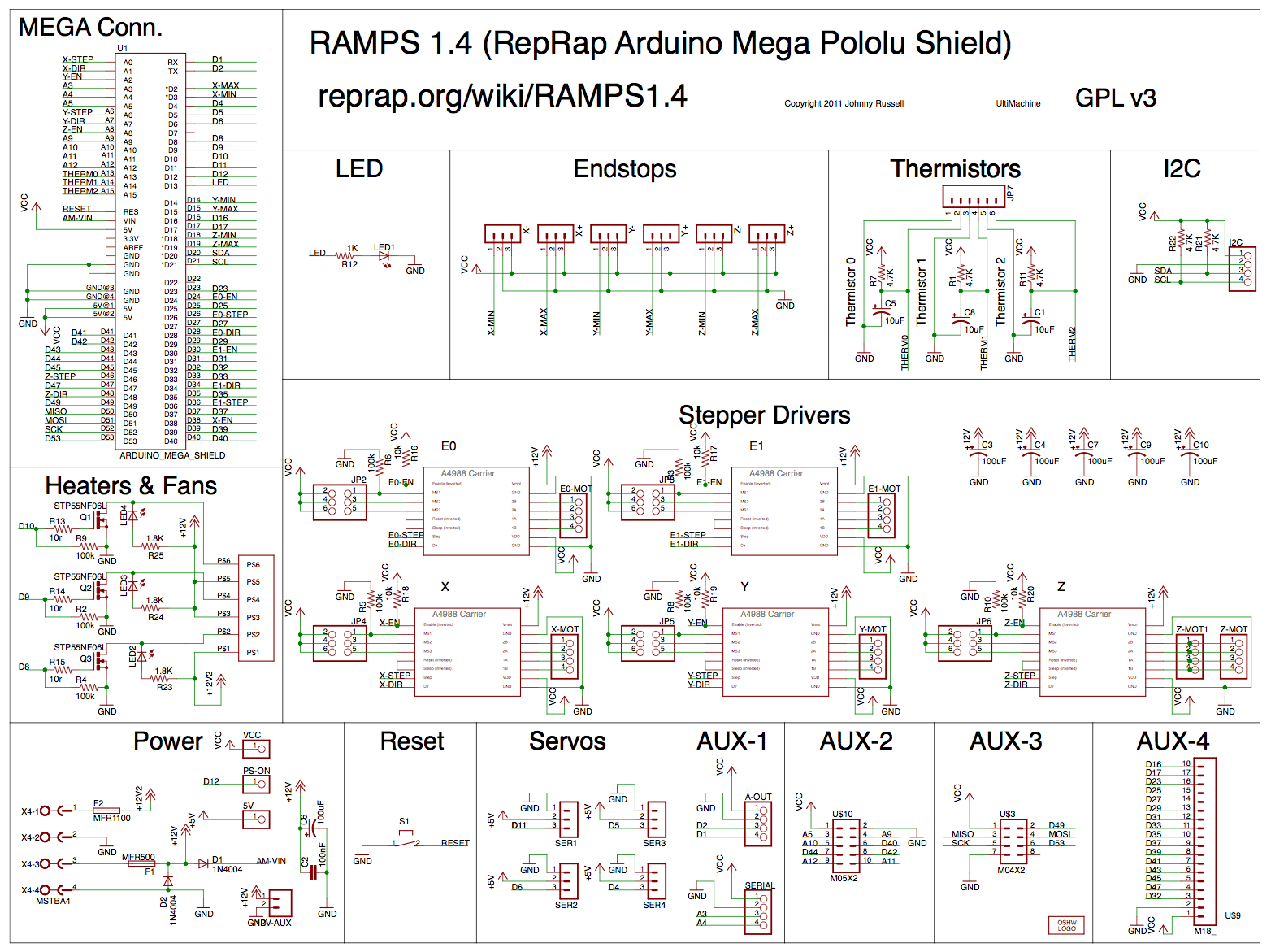
I've just finished assembling the mechanical part of CNC. Still waiting for my db25 sockets, but I want to do some test runs before connecting all bells and whistles. Anyway I'm looking at my Arduino Mega (clone) and Ramps board - and I'm thinking - is there any reason to use Ramps at all, if I'm not going to use pololu drivers? I'm also not sure if I would like to have as a permanent solution all connections made with dupont cables. I can't find any true soldering shield (well I've found one - but it's huge) for mega, but there is also a screw terminal shield like this. Probably the best would be dedicated PCB... but :)

bdurbrow commented 5 years ago

Nice work. 👍

Using the RAMPS board provides convenient connection points for the UI components. I think you'd end up doing a bunch more wiring trying to avoid using the RAMPS than you would if you just used the RAMPS for everything but the stepper drivers, and used DuPont jumpers to go from the step and direction pins on the RAMPS to the inputs on your stepper driver modules.

I'm also not sure if I would like to have as a permanent solution all connections made with dupont cables.

Um... I'm not quite sure I understand - DuPont connections are the least permanent, perhaps only bested in non-permanence by alligator clips? Did you mean you want something more permanent and robust than DuPont jumpers?

If that's what you mean... then yeah; I get the idea. That's why I designed the Gx200 & Gx540 breakout boards. I haven't posted the gerbers for them yet because I haven't gotten a chance to assemble and test them yet... but I hope to soon.

It's not soldered together yet, but all the parts are here: IMG_0656_s

Meanwhile; using the multi-pin housings for the DuPont pins helps a lot with their structural integrity (I just use an X-acto knife or a really tiny flat screwdriver to pop up the tabs on the single pin housing of the pre-made DuPont pins that come as a ribbon cable, remove the metal pins & wire from the housing, and then cluster the pins together in a new multi-pin housing).

😄

Saur0o0n commented 5 years ago

Yah, that's what I meant about dupont connector's - I don't want them to be permanent solution.

This breakout board looks awesome. I'm not sure why you put there so many ICs - but I'll wait till you create some documentation. Meanwhile I'm going to use screw terminal board - without ramps. Do you have full pinout table/schema, not by ramps sockets but just Mega pins (A1..A15,D1..D53) where to connect? If not I'll do it - but perhaps you already have it :)

bdurbrow commented 5 years ago

Most of the ICs are for buffering & level shifting. There is one RS485 driver on the board; one i2c port expander which connects to a 74HCT245 buffer (intended to drive a 8-channel relay board), and a LM358 op-amp for analog voltage output (0-10v typically).

Both boards are designed to be voltage-level compatible with ARM based Arduino's (the Due and the Adafruit Grand Central M4 are the only ones currently available in the Mega form factor, but I'm hoping someday there will be a "Mega Zero" board by the official Arduino project that we could run the ARM version of Grbl that Chamnit is developing on). That's what the 5v/3.3v jumper is for - it switches which voltage level is fed back to the Arduino board's inputs, as well as what level the i2c lines are pulled up to.

If you look in the source code; in cpu_map.h most of the UI related pin definitions are expressed as Arduino Mega pin numbers. Also, the RAMPS schematic has the rest on it.

https://reprap.org/mediawiki/images/f/f6/RAMPS1.4schematic.png

bdurbrow commented 5 years ago

Well, this is annoying.

I'm not sure how I managed to do it, but the pinouts for the connectors that go to the LCD/SD/Encoder knob PCB are wrong... half of them are left-right flipped. While it's possible to work around the issue with a wiring harness made from DuPont wires mounted in a 5x2 housing; I really want to have the header on the PCB have the right pinout so that you can just plug in the ribbon cable that the LCD board comes with.

So I'm going to have to fix the pinouts in the original file; and re-send them to China for manufacturing. Although I'm only out about $30 or so; it's another week for them to get here via DHL Express.

:unamused:

qulet commented 4 years ago

This is my DB25 PIN solution ... IMG_20190904_211915 IMG_20190904_211615

HTB1m8C6g2NNTKJjSspeq6ySwpXar All control signals go to this board and then to the controllers and the power supply.

bdurbrow commented 4 years ago

@qulet -- do you have a link to any documentation on that board?

I found the Aliexpress page where it's sold, but it didn't seem to have very much information on it.

Saur0o0n commented 4 years ago

I've seen plenty of those boards on Ali (none have any specs) - but all they where referring to Mach3 devices, so I discarded it, assuming there is some additional logic build in, not just simple optocoupling for transfer.

bdurbrow commented 4 years ago

The photos don't seem to indicate anything more than some buffering logic - 74HC245 - and some optocouplers, and a relay. I think it really is just a generic parallel port breakout; and they just reference Mach 3 because it's popular.

I'd like to check it's pinouts against the pinouts of my Gx540 design... I'm almost positive it'll be compatible - the Gx540 was designed to directly connect to a GeckoDrive G540; which itself is designed to directly plug into a PC parallel port...

I might have to grab one and reverse engineer it... it's only $5.

qulet commented 4 years ago

ST-V2.pdf 5Axis Breakout Board

Everything after connecting the GRBL Mega pin out from the * .pdf file works. The DC voltage to the inverter when supplying an additional 12V board from the PWM obtained is MAX about 8V but the same voltage was from a dedicated 0-10V PWM-DC converter board. I have two such tiles, green and blue. This last one has inverted relay logic.

Link with diagrams of such PCBs https://karusisemus.wordpress.com/2016/07/15/a-cnc-breakout-board/

bdurbrow commented 4 years ago

Looks like it uses the same pinouts as the GeckoDrive Gx540; so my Gx540 breakout board would be compatible.

The revised PCBs went off to JLC for manufacturing about 18 hours ago, so hopefully they will fly out later today.

Saur0o0n commented 4 years ago

bdurbrow - have you defined all PINs in cpu_map.h also for non RAMPs or only for RAMPs? I try to map everything in spreadsheet for now, and it seems that UI stuff is only defined in #if RAMPS section. It's not a problem - I can use RAMP's as NON RAMPS installation - just asking what to expect :) edit: Ok, I see you've disabled // #define DEFAULTS_GENERIC // #define CPU_MAP_2560_INITIAL in config.h - so only this sections are going to be valid

define DEFAULTS_RAMPS_BOARD

define CPU_MAP_2560_RAMPS_BOARD

Saur0o0n commented 4 years ago

I've created a pinout diagram for RAMPS with UI, without Geecko. Feel free to use it :) I've assumed SD card is SPI and uses all SPI pins despite only one was assigned. Why rotary encoder has two buttons defined? GRBLonMEGA.pdf GRBLonMEGA.zip

bdurbrow commented 4 years ago

I haven't done much with the non-RAMPS configuration yet. I'm not even sure it compiles right now...

Eventually, I will address that, however.

The SD card does use the hardware SPI port; that is indeed why there's only two config option for the SD pins - chip select and card detect (the latter is not used at the moment, though).

The rotary encoder has two buttons assigned because the LCD card has two buttons on it - one is the actual push action of the encoder; and the other is the button right next to it. From a UI perspective, pushing the encoder is considered a "select" operation; and pushing the other button is considered a "go back" or "escape" operation.

Nice graphics.... I'll have a closer look at it when I'm out getting dinner.

😄

Saur0o0n commented 4 years ago

Ok, so the second button is kill/reset switch - on 3d printer it's just reset.

GRBLonMEGA.pdf GRBLonMEGA.zip

Saur0o0n commented 4 years ago

I've pushed this files to git - updated it with pots - I think that's all now. Editable ODS and to view PNG & PDF to git: https://github.com/Saur0o0n/GRBL_Mega-pinout

After studying it I'm very disappointed :( since there is NO WAY to push all the human interaction stuff on single DB25 (to leave Mega close to drivers). I haven't count it before, because I got the impression it's doable, but now it looks like this would require 33 lines...

bdurbrow commented 4 years ago

Hmm... how about a SCSI cable? Centronics 50 pin, IIRC...

The signals are slow enough that I don't think termination is going to be an issue...

Saur0o0n commented 4 years ago

Yah, but I've already got all DB25 boards and cables :/ I'll check for SCSI cable - I should have a lot of them at work and see if there are any breakout boards. Good thing is that I've soldered yesterday Mega screw breakout board and it seems to be quite practical. You can even sandwich is with ramps (I'm not gone to use it - but wanted to do a quick test of LCD screen) - anyway looks nice :) 2019-09-26 11 17 22 ps. Mega is underneath - you can see only USB and power socket.

bdurbrow commented 4 years ago

IIRC, some lower quality cables - assuming that it was being used with only SCSI - skipped on some of the ground lines... so it would probably be a good idea to double check that before plugging it in...

Alternatively... um... 33-25=8... so... a DB25 and a DB9 cable run in the same raceway?

bdurbrow commented 4 years ago

Oops... wrong button. Not supposed to be closed yet!

Saur0o0n commented 4 years ago

I've found some neat SUN external SCSI cables - but with them (as I can see on ebay/aliexpress) would be a problem with sockets. I could cannibalize some old ("used to" be extremely expensive SCSI pci controllers) but this somehow doesn't feel nice. There are DB37 cables and sockets available - same price as DB25 - so this would be best option to start, but now I guess I'll add just DB15 (vga) line. DB15 is widely available and cheap, also leaves some space for expansion in future.

bdurbrow commented 4 years ago

You are probably already aware of it, but I'll throw this into the thread anyways...

Technically, VGA uses a three-row DE-15 connector (also sometimes referred to as a HD15), not a DB15 connector (which would be like a DB25, but missing 10 pins). 15 pin two-row D-sub connectors were often used for analog joystick connectors on several systems (most notably the IBM PC) and are also often (erroneously) referred to as DB-15; but the VGA and joystick connectors are not physically compatible. Consequentially, when ordering parts one should make sure that one is getting the right thing. https://en.wikipedia.org/wiki/D-subminiature

Also - better quality the VGA cables run the color signals down mini-coax lines. At the speeds that the components of the console operate; I don't think the difference in impedance is going to matter... but it is there. https://en.wikipedia.org/wiki/VGA_connector

I could cannibalize some old ("used to" be extremely expensive SCSI pci controllers) but this somehow doesn't feel nice.

Not when new parts are available for so cheap these days...

Saur0o0n commented 4 years ago

I've updated pinouts with new RPM/load/laser pins: https://github.com/Saur0o0n/GRBL_Mega-pinout

Saur0o0n commented 4 years ago

bdurbrow - so how is your progress on your board design - is it ready?

bdurbrow commented 4 years ago

I have not had a chance to work on this since mid-January or so... things got busy. I'm hoping to get back into it soon, though. First I'm going to get the promised update posted (there's still a little bit of testing I need to do; but the coding should be done); and then start work on the PCBs again.

Saur0o0n commented 3 years ago

Just to do some "leech magic" ;) - and raise some dead topics - have you finish PCB design and testing?