 peterverhagenresx
commented
1 year ago
peterverhagenresx
commented
1 year ago /**
* @file LoRaWan.ino
* @author Bernd Giesecke (bernd.giesecke@rakwireless.com)
* @brief
* @version 0.1
* @date 2021-11-26
*
* @copyright Copyright (c) 2021
*
*/
#include <Arduino.h>
#include <LoRaWan-Arduino.h>
#include <SPI.h>
#define SCHED_MAX_EVENT_DATA_SIZE APP_TIMER_SCHED_EVENT_DATA_SIZE /**< Maximum size of scheduler events. */
#define SCHED_QUEUE_SIZE 60 /**< Maximum number of events in the scheduler queue. */
#define LORAWAN_APP_DATA_BUFF_SIZE 64 /**< Size of the data to be transmitted. */
#define LORAWAN_APP_TX_DUTYCYCLE 10000 /**< Defines the application data transmission duty cycle. 10s, value in [ms]. */
#define APP_TX_DUTYCYCLE_RND 1000 /**< Defines a random delay for application data transmission duty cycle. 1s, value in [ms]. */
#define JOINREQ_NBTRIALS 3 /**< Number of trials for the join request. */
hw_config hwConfig;
#ifdef ESP32
// ESP32 - SX126x pin configuration
int PIN_LORA_RESET = 10; // LORA RESET
int PIN_LORA_NSS = 7; // LORA SPI CS
int PIN_LORA_SCLK = 4; // LORA SPI CLK
int PIN_LORA_MISO = 5; // LORA SPI MISO
int PIN_LORA_DIO_1 = 3; // LORA DIO_1
int PIN_LORA_BUSY = 0; // LORA SPI BUSY
int PIN_LORA_MOSI = 6; // LORA SPI MOSI
int RADIO_TXEN = -1; // LORA ANTENNA TX ENABLE
int RADIO_RXEN = -1; // LORA ANTENNA RX ENABLE
#endif
#ifdef ESP8266
// ESP32 - SX126x pin configuration
int PIN_LORA_RESET = 0; // LORA RESET
int PIN_LORA_NSS = 2; // LORA SPI CS
int PIN_LORA_DIO_1 = 15; // LORA DIO_1
int PIN_LORA_BUSY = 16; // LORA SPI BUSY
int PIN_LORA_SCLK = SCK; // LORA SPI CLK
int PIN_LORA_MISO = MISO; // LORA SPI MISO
int PIN_LORA_MOSI = MOSI; // LORA SPI MOSI
int RADIO_TXEN = -1; // LORA ANTENNA TX ENABLE
int RADIO_RXEN = -1; // LORA ANTENNA RX ENABLE
#endif
#ifdef NRF52_SERIES
#ifndef RAK4630
// nRF52832 - SX126x pin configuration
int PIN_LORA_RESET = 4; // LORA RESET
int PIN_LORA_NSS = 28; // LORA SPI CS
int PIN_LORA_SCLK = 12; // LORA SPI CLK
int PIN_LORA_MISO = 14; // LORA SPI MISO
int PIN_LORA_DIO_1 = 11; // LORA DIO_1
int PIN_LORA_BUSY = 29; // LORA SPI BUSY
int PIN_LORA_MOSI = 13; // LORA SPI MOSI
int RADIO_TXEN = -1; // LORA ANTENNA TX ENABLE
int RADIO_RXEN = -1; // LORA ANTENNA RX ENABLE
// Replace PIN_SPI_MISO, PIN_SPI_SCK, PIN_SPI_MOSI with your
SPIClass SPI_LORA(NRF_SPIM2, 14, 12, 13);
#endif
#endif
// Foward declaration
static void lorawan_has_joined_handler(void);
static void lorawan_rx_handler(lmh_app_data_t *app_data);
static void lorawan_confirm_class_handler(DeviceClass_t Class);
static void lorawan_join_failed_handler(void);
static void send_lora_frame(void);
static uint32_t timers_init(void);
// APP_TIMER_DEF(lora_tx_timer_id); ///< LoRa tranfer timer instance.
TimerEvent_t appTimer; ///< LoRa tranfer timer instance.
static uint8_t m_lora_app_data_buffer[LORAWAN_APP_DATA_BUFF_SIZE]; ///< Lora user application data buffer.
static lmh_app_data_t m_lora_app_data = {m_lora_app_data_buffer, 0, 0, 0, 0}; ///< Lora user application data structure.
/**@brief Structure containing LoRaWan parameters, needed for lmh_init()
*/
static lmh_param_t lora_param_init = {LORAWAN_ADR_ON, LORAWAN_DEFAULT_DATARATE, LORAWAN_PUBLIC_NETWORK, JOINREQ_NBTRIALS, LORAWAN_DEFAULT_TX_POWER, LORAWAN_DUTYCYCLE_OFF};
/**@brief Structure containing LoRaWan callback functions, needed for lmh_init()
*/
static lmh_callback_t lora_callbacks = {BoardGetBatteryLevel, BoardGetUniqueId, BoardGetRandomSeed,
lorawan_rx_handler, lorawan_has_joined_handler, lorawan_confirm_class_handler, lorawan_join_failed_handler};
#ifdef NRF52_SERIES
// Start BLE if we compile for nRF52
#include <bluefruit.h>
void initBLE();
extern bool bleUARTisConnected;
extern BLEUart bleuart;
#endif
// Check if the board has an LED port defined
#ifndef LED_BUILTIN
#ifdef ESP32
#define LED_BUILTIN 8
#endif
#ifdef NRF52_SERIES
#ifndef RAK4630
#define LED_BUILTIN 17
#endif
#endif
#endif
uint8_t nodeDeviceEUI[8] = {0x00, 0x95, 0x64, 0x1F, 0xDA, 0x91, 0x19, 0x0B};
uint8_t nodeAppEUI[8] = {0x70, 0xB3, 0xD5, 0x7E, 0xD0, 0x02, 0x01, 0xE1};
uint8_t nodeAppKey[16] = {0x07, 0xC0, 0x82, 0x0C, 0x30, 0xB9, 0x08, 0x70, 0x0C, 0x0F, 0x70, 0x06, 0x00, 0xB0, 0xBE, 0x09};
uint32_t nodeDevAddr = 0x260116F8;
uint8_t nodeNwsKey[16] = {0x7E, 0xAC, 0xE2, 0x55, 0xB8, 0xA5, 0xE2, 0x69, 0x91, 0x51, 0x96, 0x06, 0x47, 0x56, 0x9D, 0x23};
uint8_t nodeAppsKey[16] = {0xFB, 0xAC, 0xB6, 0x47, 0xF3, 0x58, 0x45, 0xC7, 0x50, 0x7D, 0xBF, 0x16, 0x8B, 0xA8, 0xC1, 0x7C};
void setup()
{
pinMode(LED_BUILTIN, OUTPUT);
digitalWrite(LED_BUILTIN, LOW);
#ifndef RAK4630
// Define the HW configuration between MCU and SX126x
hwConfig.CHIP_TYPE = SX1262_CHIP; // Example uses an eByte E22 module with an SX1262
hwConfig.PIN_LORA_RESET = PIN_LORA_RESET; // LORA RESET
hwConfig.PIN_LORA_NSS = PIN_LORA_NSS; // LORA SPI CS
hwConfig.PIN_LORA_SCLK = PIN_LORA_SCLK; // LORA SPI CLK
hwConfig.PIN_LORA_MISO = PIN_LORA_MISO; // LORA SPI MISO
hwConfig.PIN_LORA_DIO_1 = PIN_LORA_DIO_1; // LORA DIO_1
hwConfig.PIN_LORA_BUSY = PIN_LORA_BUSY; // LORA SPI BUSY
hwConfig.PIN_LORA_MOSI = PIN_LORA_MOSI; // LORA SPI MOSI
hwConfig.RADIO_TXEN = RADIO_TXEN; // LORA ANTENNA TX ENABLE
hwConfig.RADIO_RXEN = RADIO_RXEN; // LORA ANTENNA RX ENABLE
hwConfig.USE_DIO2_ANT_SWITCH = true; // Example uses an CircuitRocks Alora RFM1262 which uses DIO2 pins as antenna control
hwConfig.USE_DIO3_TCXO = true; // Example uses an CircuitRocks Alora RFM1262 which uses DIO3 to control oscillator voltage
hwConfig.USE_DIO3_ANT_SWITCH = false; // Only Insight ISP4520 module uses DIO3 as antenna control
#endif
// Initialize Serial for debug output
Serial.begin(115200);
Serial.println("=====================================");
Serial.println("SX126x LoRaWan test");
Serial.println("=====================================");
#ifdef NRF52_SERIES
pinMode(30, OUTPUT);
digitalWrite(30, HIGH);
// Start BLE if we compile for nRF52
initBLE();
#endif
#ifndef RAK4630
// Initialize LoRa chip.
uint32_t err_code = lora_hardware_init(hwConfig);
if (err_code != 0)
{
Serial.printf("lora_hardware_init failed - %d\n", err_code);
}
#else
// Initialize LoRa chip.
uint32_t err_code = lora_rak4630_init();
if (err_code != 0)
{
Serial.printf("lora_hardware_init failed - %d\n", err_code);
}
#endif
// Initialize Scheduler and timer (Must be after lora_hardware_init)
err_code = timers_init();
if (err_code != 0)
{
Serial.printf("timers_init failed - %d\n", err_code);
}
// Setup the EUIs and Keys
lmh_setDevEui(nodeDeviceEUI);
lmh_setAppEui(nodeAppEUI);
lmh_setAppKey(nodeAppKey);
lmh_setNwkSKey(nodeNwsKey);
lmh_setAppSKey(nodeAppsKey);
lmh_setDevAddr(nodeDevAddr);
// Initialize LoRaWan
err_code = lmh_init(&lora_callbacks, lora_param_init, true, CLASS_A, LORAMAC_REGION_AU915);
if (err_code != 0)
{
Serial.printf("lmh_init failed - %d\n", err_code);
}
//!!!!!!!!!!!!!!!!!!!!!!!!!!!!!!!!!!!!!!!!!!!!!!!!!!!!!!!!!!!!!!!!!!!!!!!!!!!!!!
// Use either
// lmh_setSingleChannelGateway
// or
// lmh_setSubBandChannels
//
// DO NOT USE BOTH OR YOUR COMMUNICATION WILL MOST LIKELY NEVER WORK
//!!!!!!!!!!!!!!!!!!!!!!!!!!!!!!!!!!!!!!!!!!!!!!!!!!!!!!!!!!!!!!!!!!!!!!!!!!!!!!
// Setup connection to a single channel gateway
// lmh_setSingleChannelGateway(0, DR_3);
// For some regions we might need to define the sub band the gateway is listening to
// This must be called AFTER lmh_init()
/// \todo This is for Dragino LPS8 gateway. How about other gateways???
if (!lmh_setSubBandChannels(1))
{
Serial.println("lmh_setSubBandChannels failed. Wrong sub band requested?");
}
// Start Join procedure
lmh_join();
}
void loop()
{
#ifdef ESP8266
// Handle Radio events
Radio.IrqProcess();
#endif
// We are on FreeRTOS, give other tasks a chance to run
// delay(100);
}
/**@brief LoRa function for handling OTAA join failed
*/
static void lorawan_join_failed_handler(void)
{
Serial.println("OVER_THE_AIR_ACTIVATION failed!");
Serial.println("Check your EUI's and Keys's!");
Serial.println("Check if a Gateway is in range!");
}
/**@brief LoRa function for handling HasJoined event.
*/
static void lorawan_has_joined_handler(void)
{
#if (OVER_THE_AIR_ACTIVATION != 0)
Serial.println("Network Joined");
#else
Serial.println("OVER_THE_AIR_ACTIVATION != 0");
#endif
lmh_class_request(CLASS_A);
TimerSetValue(&appTimer, LORAWAN_APP_TX_DUTYCYCLE);
TimerStart(&appTimer);
}
/**@brief Function for handling LoRaWan received data from Gateway
@param[in] app_data Pointer to rx data
*/
static void lorawan_rx_handler(lmh_app_data_t *app_data)
{
Serial.printf("LoRa Packet received on port %d, size:%d, rssi:%d, snr:%d\n",
app_data->port, app_data->buffsize, app_data->rssi, app_data->snr);
switch (app_data->port)
{
case 3:
// Port 3 switches the class
if (app_data->buffsize == 1)
{
switch (app_data->buffer[0])
{
case 0:
lmh_class_request(CLASS_A);
break;
case 1:
lmh_class_request(CLASS_B);
break;
case 2:
lmh_class_request(CLASS_C);
break;
default:
break;
}
}
break;
case LORAWAN_APP_PORT:
// YOUR_JOB: Take action on received data
break;
default:
break;
}
}
static void lorawan_confirm_class_handler(DeviceClass_t Class)
{
Serial.printf("switch to class %c done\n", "ABC"[Class]);
// Informs the server that switch has occurred ASAP
m_lora_app_data.buffsize = 0;
m_lora_app_data.port = LORAWAN_APP_PORT;
lmh_send(&m_lora_app_data, LMH_UNCONFIRMED_MSG);
}
static void send_lora_frame(void)
{
if (lmh_join_status_get() != LMH_SET)
{
//Not joined, try again later
Serial.println("Did not join network, skip sending frame");
return;
}
uint32_t i = 0;
m_lora_app_data.port = LORAWAN_APP_PORT;
m_lora_app_data.buffer[i++] = 'H';
m_lora_app_data.buffer[i++] = 'e';
m_lora_app_data.buffer[i++] = 'l';
m_lora_app_data.buffer[i++] = 'l';
m_lora_app_data.buffer[i++] = 'o';
m_lora_app_data.buffer[i++] = ' ';
m_lora_app_data.buffer[i++] = 'w';
m_lora_app_data.buffer[i++] = 'o';
m_lora_app_data.buffer[i++] = 'r';
m_lora_app_data.buffer[i++] = 'l';
m_lora_app_data.buffer[i++] = 'd';
m_lora_app_data.buffer[i++] = '!';
m_lora_app_data.buffsize = i;
lmh_error_status error = lmh_send(&m_lora_app_data, LMH_UNCONFIRMED_MSG);
Serial.printf("lmh_send result %d\n", error);
}
/**@brief Function for handling a LoRa tx timer timeout event.
*/
static void tx_lora_periodic_handler(void)
{
TimerSetValue(&appTimer, LORAWAN_APP_TX_DUTYCYCLE);
TimerStart(&appTimer);
Serial.println("Sending frame");
send_lora_frame();
}
/**@brief Function for the Timer initialization.
@details Initializes the timer module. This creates and starts application timers.
*/
static uint32_t timers_init(void)
{
appTimer.timerNum = 3;
TimerInit(&appTimer, tx_lora_periodic_handler);
return 0;
} beegee-tokyo
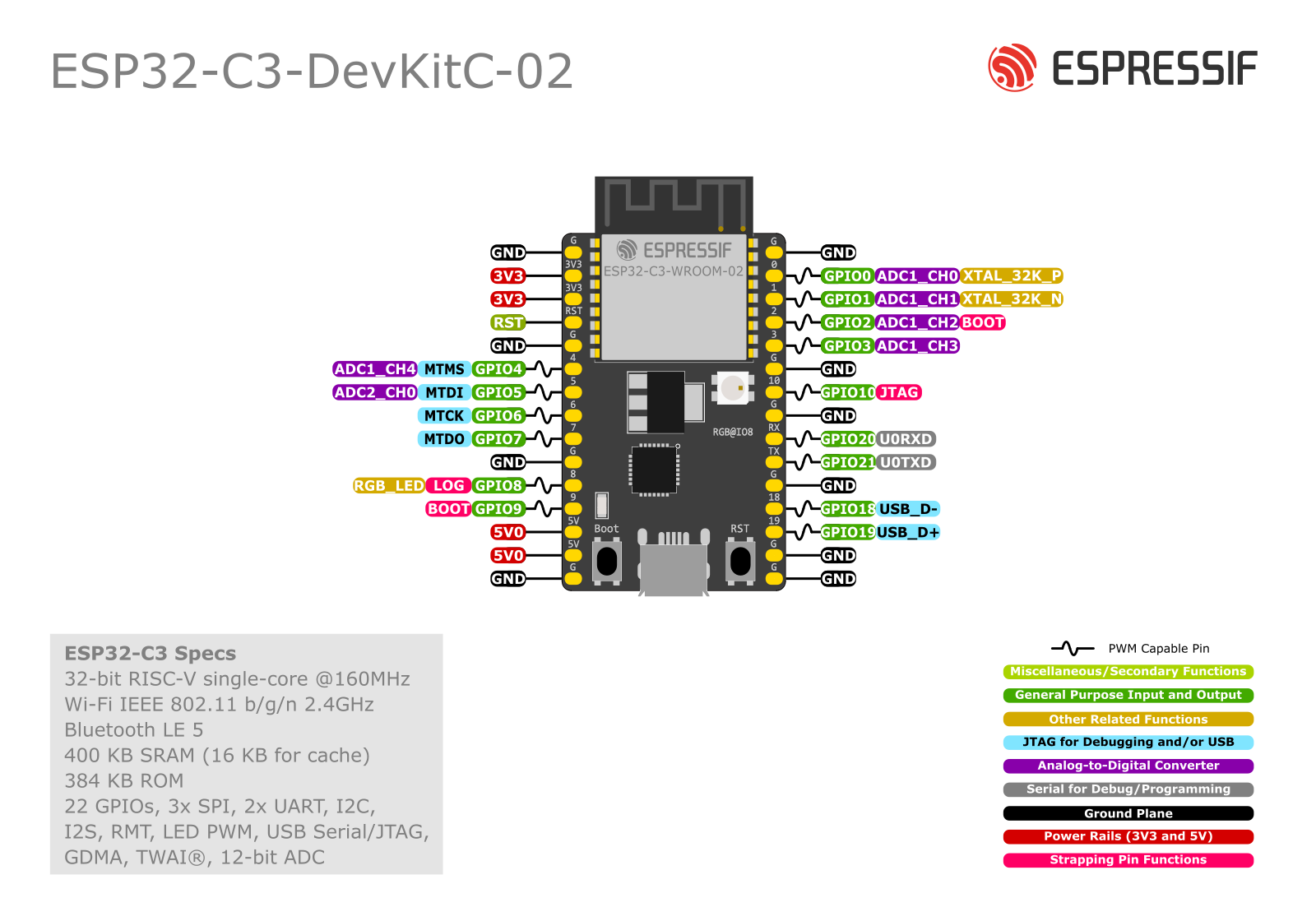
16:44:50.556 -> ESP-ROM:esp32c3-api1-20210207 16:44:50.588 -> Build:Feb 7 2021 16:44:50.588 -> rst:0x1 (POWERON),boot:0xc (SPI_FAST_FLASH_BOOT) 16:44:50.588 -> SPIWP:0xee 16:44:50.588 -> mode:DIO, clock div:1 16:44:50.588 -> load:0x3fcd5810,len:0x438 16:44:50.588 -> load:0x403cc710,len:0x91c 16:44:50.588 -> load:0x403ce710,len:0x25b0 16:44:50.588 -> entry 0x403cc710 16:44:50.654 -> E (95) esp_core_dump_flash: Core dump data check failed: 16:44:50.654 -> Calculated checks===================================== 16:44:50.654 -> SX126x LoRaWan test 16:44:50.654 -> ===================================== 16:44:50.687 -> lora_hardware_init failed - 1Using an esp32-c3 board Does any information exist on what error 1 means? Ta! PV