bigtreetech / BIGTREETECH-GTR-V1.0

BIGTREETECH GTR V1.0 motherboard is a high-performance 3D printer main control board with the core controller STM32F407IGT6, which was launched by the 3D printing team of ShenZhen BigTree Technology CO.,LTD ., aiming at solving some problems existing in the motherboard market. The BIGTREETECH GTR V1.0 is the motherboard, and the BIGTREETECH M5 V1.0 is the expansion board.
90 stars 55 forks source link

[GUIDE] to using PT100 or PT1000 or Thermocouples with SKR PRO V1.x boards or GTR V1.0 boards #40

Open GadgetAngel opened 3 years ago

GadgetAngel commented 3 years ago

GUIDE:

  1. You CAN NOT mix PT100/PT1000 and thermocouples:

If you have only one hotend then you can have the following:

If you have two hotends then you can have the following:

If you have two hot-ends then you CAN NOT have the following:

*** If you only have ONE PT100 (or PT1000 or Thermocouple) on your printer and you have two hotends then in Marlin you must use TEMP_SENSOR_0 as the PT100 (or PT1000 or Thermocouple) even if you have the PT100 (or PT1000 or Thermocouple) hooked up to the second extruder. Just override your PIN definitions to have TEMP_0_PIN point to where the PT100 (or PT1000 or Thermocouple) is located.


  1. Marlin still uses the old naming scheme of the 20x4 display REPRAP_DISCOUNT_SMART_CONTROLLER in the pins-file for the software SPI pins names: The EXP1 and EXP2 ports are used for display screens. EXP2 contains a HARDWARE SPI bus while EXP1 contains a Software SPI bus. The EXP2 hardware SPI bus signal names are obvious in the pins-file but the EXP1 software SPI bus signal names are NOT obvious. Here is the EXP1 software SPI bus signal names used in pins-file with their corresponding SPI software functions:
    LCD_PINS_D4 is software SPI signal SCK for EXP1
    LCD_PINS_ENABLE is the data line or software SPI signal MOSI for EXP1
    LCD_PINS_RS is Register select (command/data) or software SPI signal SS for EXP1

  1. Translation table to be used (or Thermistor table) depends on the power you supply to the amplifier board and the ADC reference voltage of the MCU:

GTR V1 0 Overvoltage Protection Block

On the GTR V1.0 board, here is a list of PINS that you will need to prevent negative current injection. We prevent negative current from flowing into the MCU by using a Schottky diode between the output signal of the amplifier board and ground. I do this as preventive measure. It protects the MCU from getting fried.

GTR V1 0 Prevent Negative Current Injection GTR V1 0 Footnote 3 block

The below wiring diagram for PT100 using Analog ADC input using 5V DC for the E3D's PT100 amplifier board but the MCU board (GTR V1.0) uses 3.3 VDC ADC reference voltage, therefore the Thermistor table to use for this is Table 21:

g_PT100_Technique#2_Method#1_PF8_wiring_diagram_Page_27

The below wiring diagram is for PT100 using Analog ADC input using 5V DC for the E3D's PT100 amplifier board but the MCU board (SKR MINI E3 V2.0) uses 3.3 VDC ADC reference voltage, therefore the Thermistor table to use for this is Table 21: PT100 Analog hook up with 5 VDC power for SKR MINI E3 V2 0

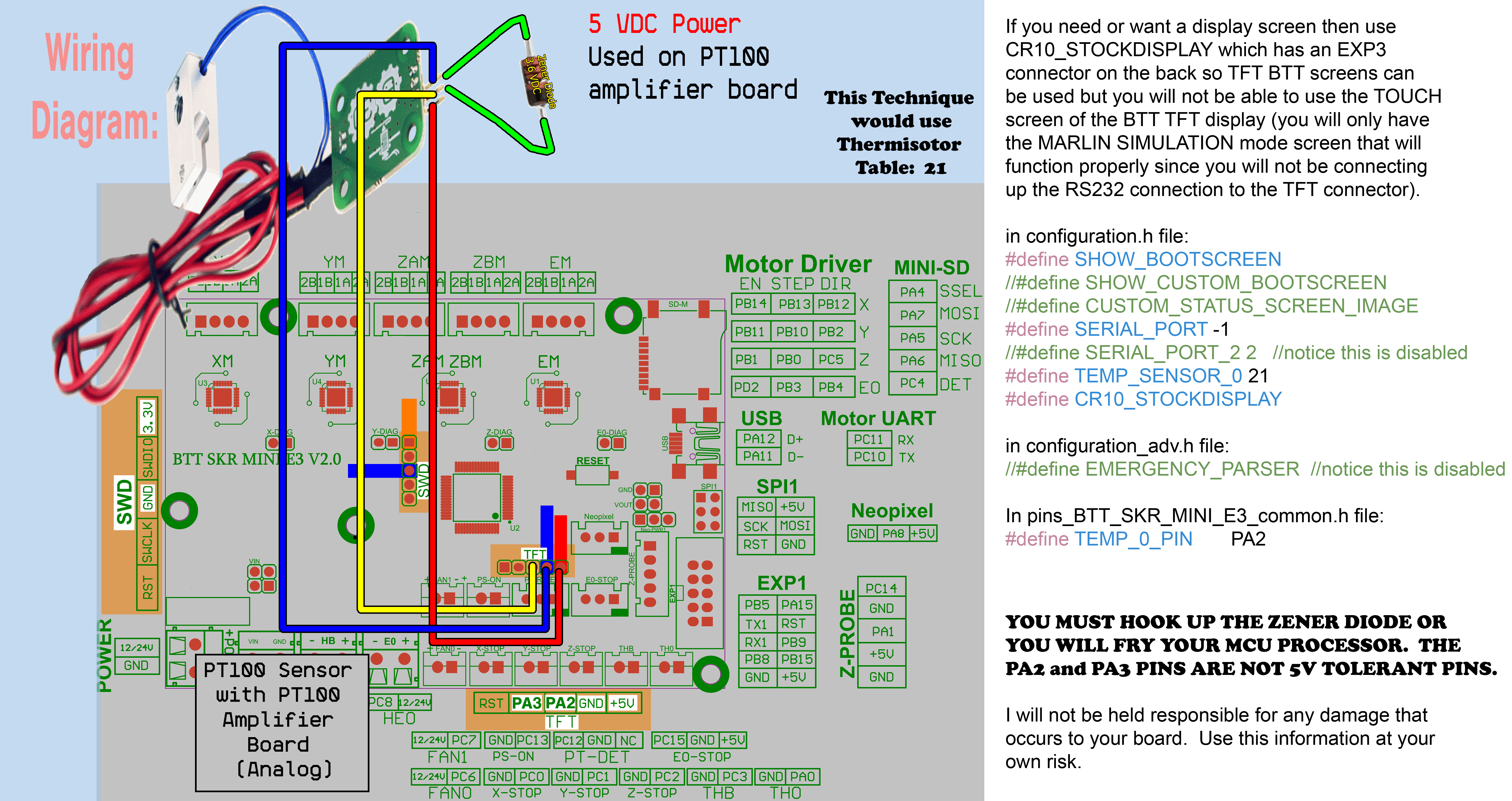
The below wiring diagram for PT100 using Analog ADC input using 3.3 VDC for the E3D's PT100 amplifier board but the MCU board (GTR V1.0 board) uses 3.3 VDC ADC reference voltage, therefore the Thermistor table to use for this is Table 20 (see the process data sheet and you will find that PF10 need protection against negative current injection,https://www.st.com/resource/en/datasheet/stm32f407ig.pdf#page=114):

G_PT100_Technique#4_Method#1_PF10_wiring_diagram_Page_29

The below wiring diagram is for PT100 using Analog ADC input using 3.3V DC for the E3D's PT100 amplifier board but the MCU board (SKR MINI E3 V2.0) uses 3.3 VDC ADC reference voltage, therefore the Thermistor table to use for this is Table 20: PT100 Analog hook up with 3 3VDC power for SKR MINI E3 V2 0


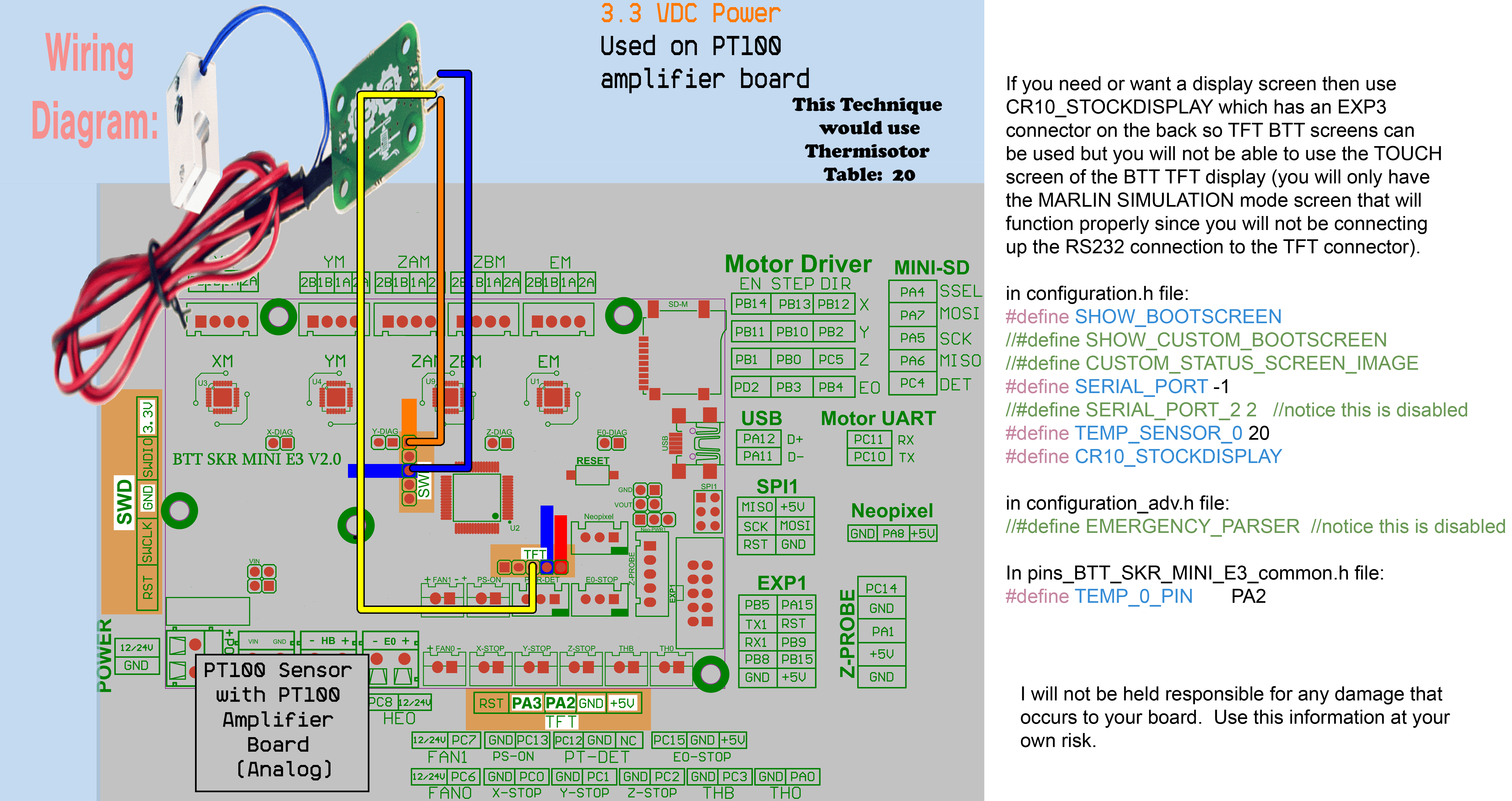
The information contained in [1, 4-14] are for the Adafruit MAX31865 board (PT100/PT100 sensors)


4A. For Marlin 2.0.7.1 or earlier versions of Marlin: If you want to use the Adafruit MAX31865 board with a PT100, you MUST correct the calibration resistor value that Marlin uses in temperature.cpp as follows: If you search in temperature.cpp for the string "max31865.temperature(", there are ONLY two places in temperature.cpp that will be found: Original is: max31865.temperature(100, 400) // 100 ohms = PT100 resistance. 400 ohms = calibration resistor CHANGE TO: max31865.temperature(100, 430) // 100 ohms = PT100 resistance. 400 ohms = calibration resistor

4B. For Marlin 2.0.7.2: If you want to use the Adafruit MAX31865 boards with a PT100, you MUST use the Marlin variables in the configuration.h file to adjust the sensor resistance ohm value and calibration resistance ohm value as shown below. If they are not present in configuration.h file then you will need to add the two statements below to configuration.h file. Use the Marlin variables instead of making the change in the Marlin software in temperature.cpp as stated in 4A.

In configuration.h file:

// for TEMP_SENSOR_0:
#define MAX31865_SENSOR_OHMS 100
#define MAX31865_CALIBRATION_OHMS 430

4C. For Marlin bugfix-2.0.x branch or later versions of Marlin: If you want to use the Adafruit MAX31865 boards with a PT100, you MUST use the Marlin variables in the configuration.h file to adjust the sensor resistance ohm value and calibration resistance ohm value as shown below. Use the Marlin variables instead of making the changes in the Marlin software in temperature.cpp as stated in 4A. If you only have one (1) Adafruit MAX31865 board than use the Marlin variable MAX31865_SENSOR_OHMS_0 and Marlin variable MAX31865_CALIBRATION_OHMS_0 only (disable MAX31865_SENSOR_OHMS_1 and disable MAX31865_CALIBRATION_OHMS_1). If you have two (2) Adafruit MAX31865 boards then enable all four Marlin variables: MAX31865_SENSOR_OHMS_0, MAX31865_CALIBRATION_OHMS_0, MAX31865_SENSOR_OHMS_1, and MAX31865_CALIBRATION_OHMS_1.

In configuration.h file:

// for TEMP_SENSOR_0:
#define MAX31865_SENSOR_OHMS_0 100
#define MAX31865_CALIBRATION_OHMS_0 430
// for TEMP_SENSOR_1:
#define MAX31865_SENSOR_OHMS_1 100
#define MAX31865_CALIBRATION_OHMS_1 430

5A. For Marlin 2.0.7.1 or earlier versions of Marlin: If you want to use the Adafruit MAX31865 board with a PT1000, you MUST correct the resistor values that Marlin uses in temperature.cpp as follows: If you search in temperature.cpp for the string "max31865.temperature(", there are ONLY two places in temperature.cpp that will be found: Original is: max31865.temperature(100, 400) // 100 ohms = PT100 resistance. 400 ohms = calibration resistor CHANGE TO: max31865.temperature(1000, 4300) // 100 ohms = PT100 resistance. 400 ohms = calibration resistor

5B. For Marlin 2.0.7.2: If you want to use the Adafruit MAX31865 boards with a PT1000, you MUST use the Marlin variables in the configuration.h file to adjust the sensor resistance ohm value and calibration resistance ohm value as shown below. If they are not present in configuration.h file then you will need to add the two statements below to configuration.h file. Use the Marlin variables instead of making the change in the Marlin software in temperature.cpp as stated in 5A.

In configuration.h file:

// for TEMP_SENSOR_0:
#define MAX31865_SENSOR_OHMS 1000
#define MAX31865_CALIBRATION_OHMS 4300

5C. For Marlin bugfix-2.0.x branch or later versions of Marlin: If you want to use the Adafruit MAX31865 boards with a PT1000, you MUST use the Marlin variables in the configuration.h file to adjust the sensor resistance ohm value and calibration resistance ohm value as shown below. Use the Marlin variables instead of making the changes in the Marlin software in temperature.cpp as stated in 5A. If you only have one (1) Adafruit MAX31865 board than use the Marlin variable MAX31865_SENSOR_OHMS_0 and Marlin variable MAX31865_CALIBRATION_OHMS_0 only (disable MAX31865_SENSOR_OHMS_1 and disable MAX31865_CALIBRATION_OHMS_1). If you have two (2) Adafruit MAX31865 boards then enable all four Marlin variables: MAX31865_SENSOR_OHMS_0, MAX31865_CALIBRATION_OHMS_0, MAX31865_SENSOR_OHMS_1, and MAX31865_CALIBRATION_OHMS_1.

In configuration.h file:

// for TEMP_SENSOR_0:
#define MAX31865_SENSOR_OHMS_0 1000
#define MAX31865_CALIBRATION_OHMS_0 4300
// for TEMP_SENSOR_1:
#define MAX31865_SENSOR_OHMS_1 1000
#define MAX31865_CALIBRATION_OHMS_1 4300

  1. You must prepare the Adafruit MAX31865 board for 2_WIRE_MODE because that is the ONLY mode for the Adafruit MAX31865 board that Marlin supports.

Do the following to prepare the Adafruit MAX31865 board correctly:

You need to solder two bridges on the MAX31865 board. Marlin will only read an RTD which have 2-Wire configuration. (https://voron.dozuki.com/Guide/How+to+Use+a+Pt100+Thermistor+w-+Skr+Boards/73?lang=en). Ensure your PT100 is hooked to the middle two terminals.

Preparing the MAX31865 board


  1. If you want to use the Adafruit MAX31865 board for PT100 sensor or PT1000 sensor then ENSURE that the Adafruit MAX31865 library is NOT the most recent update by doing the following: Check that in platformio.ini file the following line exists in [common] under lib_deps = and feature dependencies [features]: MAX6675_IS_MAX31865 = Adafruit MAX31865 library@~1.1.0

  1. Do I have a 100 ohm or 1000 ohm MAX31865 board? Here is how you tell:

Do I have a 100 ohm or 1000 ohm MAX31865 board


  1. If you want to use PT100 temperature sensor with the Adafruit MAX31865 over SPI you have two options: A. Software SPI (where the MCU performs the handshake in software) B. Hardware SPI (where the MCU performs the handshake with hardware interrupts).

  2. If you want to use the Hardware SPI for Adafruit MAX31865, then you have to know which SPI bus on the MCU board is the default hardware SPI bus (SPI Bus 1 or SPI Bus 2) due to the fact that the Adafruit MAX31865 Library will default to this bus (Adafruit MAX31865 library does not expose the bus number, so it just defaults).

11A. How to determine the default hardware SPI bus for a the SKR boards: To determine the default hardware SPI bus for BTT SKR boards, look at the following Marlin variable:

  1. SDCARDCONNECTION in your boards pins[your board].h file
  2. SDSUPPORT in configuration.h file
  3. SDCARD_CONNECTION in configuration_adv.h file

In the pins-file (Marlin\src\pins) for the board, look for the following Marlin variables:

//
// SD Support
//

#ifndef SDCARD_CONNECTION
  #define SDCARD_CONNECTION                  LCD
#endif

and in configuration.h file:

/**
 * SD CARD
 *
 * SD Card support is disabled by default. If your controller has an SD slot,
 * you must uncomment the following option or it won't work.
 */
#define SDSUPPORT

and in configuratio_adv.h file:

  /**
   * Set this option to one of the following (or the board's defaults apply):
   *
   *           LCD - Use the SD drive in the external LCD controller.
   *       ONBOARD - Use the SD drive on the control board. (No SD_DETECT_PIN. M21 to init.)
   *  CUSTOM_CABLE - Use a custom cable to access the SD (as defined in a pins file).
   *
   * :[ 'LCD', 'ONBOARD', 'CUSTOM_CABLE' ]
   */
  //#define SDCARD_CONNECTION LCD

Below is a table indicates the default hardware SPI bus for the BTT SKR series of boards:

     board                      pins-file                              SDCARD_CONNECTION setting                      default HW SPI BUS number
---------------           ------------------                       -------------------------------                    --------------------------
SKR-mini-V1.1.............pins_BTT_SKR_MINI_V1_1.h.............................ONBOARD.............................................1 (micro SD card reader)  when SDSUPPORT is enabled or disabled in configuration.h file as long as ONBOARD_SPI_DEVICE in pins_BTT_SKR_MINI_V1_1.h is set to 1; Use JSER Micro SD TF Memory Card Kit Male to Female Extension Adapter (https://www.amazon.com/gp/product/B071DKCK47/).  When you have a device hooked up to the micro-SD card reader, disconnect the power to the MAX temperature sensor board  (remove GND and VIN from the MAX board) when doing a firmware update via the micro-SD card reader.  If you do not disconnect the power your micro-SD card can become corrupted. To over come the fact that BTT put a pull-up resistor on the SCLK line of the micro-SD card reader you might have to add a compile directive to tell the software to use SPI_MODE3 instead of SPI_MODE0.  This feature has not yet been added to the bugfix branch of Marlin.  But be aware that for the MAX31855 and MA31865 boards you will need to use SPI_MODE3 when using hardware SPI, for the MAX6675 you will need to use SPI_MODE2 when using hardware SPI.
SKR-mini-V1.1.............pins_BTT_SKR_MINI_V1_1.h.............................LCD.................................................1 (mico SD card reader) NOTE: SDSUPPORT is disabled in configuration.h file as long as ONBOARD_SPI_DEVICE in pins_BTT_SKR_MINI_V1_1.h is set to 1. Use JSER Micro SD TF Memory Card Kit Male to Female Extension Adapter (https://www.amazon.com/gp/product/B071DKCK47/).  When you have a device hooked up to the micro-SD card reader, disconnect the power to the MAX temperature sensor board  (remove GND and VIN from the MAX board) when doing a firmware update via the micro-SD card reader.  If you do not disconnect the power your micro-SD card can become corrupted. To over come the fact that BTT put a pull-up resistor on the SCLK line of the micro-SD card reader you might have to add a compile directive to tell the software to use SPI_MODE3 instead of SPI_MODE0.  This feature has not yet been added to the bugfix branch of Marlin.  But be aware that for the MAX31855 and MA31865 boards you will need to use SPI_MODE3 when using hardware SPI, for the MAX6675 you will need to use SPI_MODE2 when using hardware SPI.
SKR-mini-V1.1.............pins_BTT_SKR_MINI_V1_1.h.............................LCD.................................................3 (EXP2) NOTE: SDSPPORT is enabled in configruation.h file. Use EXP2 clamp on ribbon cable connector from https://www.digikey.com/product-detail/en/te-connectivity-amp-connectors/1658622-1/AKC10B-ND/825411 to acess the EXP2 SPI lines. The following EXP2 pins are used: PB3 as SCLK, PB4 as MISO and PB5 as MOSI
SKR mini E3 V1.0..........pins_BTT_SKR_MINI_E3_common.h........................ONBOARD.............................................1 (micro SD card reader)  when SDSUPPORT is enabled or disabled in configuration.h file as long as ONBOARD_SPI_DEVICE in pins_BTT_SKR_MINI_E3_common.h is set to 1(look at Marlin\src\HAL\STM32F1\spi_pins.h file; "1" means you are using PA5 as SCLK, PA6 as MISO and PA7 as MOSI.); Use SPI1 header PINS.  When you have a device hooked up to the SPI header pins, disconnect the power to the MAX temperature sensor board  (remove GND and VIN from the MAX board) when doing a firmware update via the micro-SD card reader.  If you do not disconnect the power your micro-SD card can become corrupted. To over come the fact that BTT put a pull-up resistor on the SCLK line of the micro-SD card reader you might have to add a compile directive to tell the software to use SPI_MODE3 instead of SPI_MODE0.  This feature has not yet been added to the bugfix branch of Marlin.  But be aware that for the MAX31855 and MA31865 boards you will need to use SPI_MODE3 when using hardware SPI, for the MAX6675 you will need to use SPI_MODE2 when using hardware SPI.
SKR mini E3 V1.0..........pins_BTT_SKR_MINI_E3_common.h........................LCD.................................................1 (micro SD card reader) NOTE: SDSUPPORT is enabled or disabled in configuration.h file as long as ONBOARD_SPI_DEVICE in pins_BTT_SKR_MINI_E3_common.h is set to 1(look at Marlin\src\HAL\STM32F1\spi_pins.h file; "1" means you are using PA5 as SCLK, PA6 as MISO and PA7 as MOSI.); Use SPI1 header PINS.  When you have a device hooked up to the SPI header pins, disconnect the power to the MAX temperature sensor board  (remove GND and VIN from the MAX board) when doing a firmware update via the micro-SD card reader.  If you do not disconnect the power your micro-SD card can become corrupted. To over come the fact that BTT put a pull-up resistor on the SCLK line of the micro-SD card reader you might have to add a compile directive to tell the software to use SPI_MODE3 instead of SPI_MODE0.  This feature has not yet been added to the bugfix branch of Marlin.  But be aware that for the MAX31855 and MA31865 boards you will need to use SPI_MODE3 when using hardware SPI, for the MAX6675 you will need to use SPI_MODE2 when using hardware SPI.
SKR mini E3 V1.2..........pins_BTT_SKR_MINI_E3_common.h........................ONBOARD.............................................1 (micro SD card reader)  when SDSUPPORT is enabled or disabled in configuration.h file as long as ONBOARD_SPI_DEVICE in pins_BTT_SKR_MINI_E3_common.h is set to 1(look at Marlin\src\HAL\STM32F1\spi_pins.h file; "1" means you are using PA5 as SCLK, PA6 as MISO and PA7 as MOSI.); Use SPI1 header PINS.  When you have a device hooked up to the SPI header pins, disconnect the power to the MAX temperature sensor board  (remove GND and VIN from the MAX board) when doing a firmware update via the micro-SD card reader.  If you do not disconnect the power your micro-SD card can become corrupted. To over come the fact that BTT put a pull-up resistor on the SCLK line of the micro-SD card reader you might have to add a compile directive to tell the software to use SPI_MODE3 instead of SPI_MODE0.  This feature has not yet been added to the bugfix branch of Marlin.  But be aware that for the MAX31855 and MA31865 boards you will need to use SPI_MODE3 when using hardware SPI, for the MAX6675 you will need to use SPI_MODE2 when using hardware SPI.
SKR mini E3 V1.2..........pins_BTT_SKR_MINI_E3_common.h........................LCD.................................................1 (micro SD card reader) NOTE: SDSUPPORT is enabled or disabled in configuration.h file as long as ONBOARD_SPI_DEVICE in pins_BTT_SKR_MINI_E3_common.h is set to 1(look at Marlin\src\HAL\STM32F1\spi_pins.h file; "1" means you are using PA5 as SCLK, PA6 as MISO and PA7 as MOSI.); Use SPI1 header PINS.  When you have a device hooked up to the SPI header pins, disconnect the power to the MAX temperature sensor board  (remove GND and VIN from the MAX board) when doing a firmware update via the micro-SD card reader.  If you do not disconnect the power your micro-SD card can become corrupted. To over come the fact that BTT put a pull-up resistor on the SCLK line of the micro-SD card reader you might have to add a compile directive to tell the software to use SPI_MODE3 instead of SPI_MODE0.  This feature has not yet been added to the bugfix branch of Marlin.  But be aware that for the MAX31855 and MA31865 boards you will need to use SPI_MODE3 when using hardware SPI, for the MAX6675 you will need to use SPI_MODE2 when using hardware SPI.
SKR mini E3 V2.0..........pins_BTT_SKR_MINI_E3_common.h........................LCD.................................................1 (micro SD card reader) NOTE: SDSUPPORT is enabled or disabled in configuration.h file as long as ONBOARD_SPI_DEVICE in pins_BTT_SKR_MINI_E3_common.h is set to 1(look at Marlin\src\HAL\STM32F1\spi_pins.h file; "1" means you are using PA5 as SCLK, PA6 as MISO and PA7 as MOSI.); Use SPI1 header PINS.  When you have a device hooked up to the SPI header pins, disconnect the power to the MAX temperature sensor board  (remove GND and VIN from the MAX board) when doing a firmware update via the micro-SD card reader.  If you do not disconnect the power your micro-SD card can become corrupted. To over come the fact that BTT put a pull-up resistor on the SCLK line of the micro-SD card reader you might have to add a compile directive to tell the software to use SPI_MODE3 instead of SPI_MODE0.  This feature has not yet been added to the bugfix branch of Marlin.  But be aware that for the MAX31855 and MA31865 boards you will need to use SPI_MODE3 when using hardware SPI, for the MAX6675 you will need to use SPI_MODE2 when using hardware SPI.  See item 14 below and EXAMPLE 2 for a wiring diagram and instructions.
SKR mini E3 V2.0..........pins_BTT_SKR_MINI_E3_common.h........................ONBOARD.............................................1 (micro SD card reader)  when SDSUPPORT is enabled or disabled in configuration.h file as long as ONBOARD_SPI_DEVICE in pins_BTT_SKR_MINI_E3_common.h is set to 1(look at Marlin\src\HAL\STM32F1\spi_pins.h file; "1" means you are using PA5 as SCLK, PA6 as MISO and PA7 as MOSI.); Use SPI1 header PINS.  When you have a device hooked up to the SPI header pins, disconnect the power to the MAX temperature sensor board  (remove GND and VIN from the MAX board) when doing a firmware update via the micro-SD card reader.  If you do not disconnect the power your micro-SD card can become corrupted. To over come the fact that BTT put a pull-up resistor on the SCLK line of the micro-SD card reader you might have to add a compile directive to tell the software to use SPI_MODE3 instead of SPI_MODE0.  This feature has not yet been added to the bugfix branch of Marlin.  But be aware that for the MAX31855 and MA31865 boards you will need to use SPI_MODE3 when using hardware SPI, for the MAX6675 you will need to use SPI_MODE2 when using hardware SPI.  See item 14 below and EXAMPLE 2 for a wiring diagram and instructions.
SKR mini MZ V1.0..........pins_BTT_SKR_MINI_E3_common.h........................ONBOARD.............................................1 (micro SD card reader)  when SDSUPPORT is enabled or disabled in configuration.h file as long as ONBOARD_SPI_DEVICE in pins_BTT_SKR_MINI_E3_common.h is set to 1(look at Marlin\src\HAL\STM32F1\spi_pins.h file; "1" means you are using PA5 as SCLK, PA6 as MISO and PA7 as MOSI.); Use JSER Micro SD TF Memory Card Kit Male to Female Extension Adapter (https://www.amazon.com/gp/product/B071DKCK47/). When you have a device is hooked up to the micro-SD card reader, disconnect the power to the MAX temperature sensor board  (remove GND and VIN from the MAX board) when doing a firmware update via the micro-SD card reader.  If you do not disconnect the power your micro-SD card can become corrupted. To over come the fact that BTT put a pull-up resistor on the SCLK line of the micro-SD card reader you might have to add a compile directive to tell the software to use SPI_MODE3 instead of SPI_MODE0.  This feature has not yet been added to the bugfix branch of Marlin.  But be aware that for the MAX31855 and MA31865 boards you will need to use SPI_MODE3 when using hardware SPI, for the MAX6675 you will need to use SPI_MODE2 when using hardware SPI.
SKR mini MZ V1.0..........pins_BTT_SKR_MINI_E3_common.h........................LCD.................................................1 (micro SD card reader) NOTE: SDSUPPORT is enabled or disabled in configuration.h file as long as ONBOARD_SPI_DEVICE in pins_BTT_SKR_MINI_E3_common.h is set to 1(look at Marlin\src\HAL\STM32F1\spi_pins.h file; "1" means you are using PA5 as SCLK, PA6 as MISO and PA7 as MOSI.); Use JSER Micro SD TF Memory Card Kit Male to Female Extension Adapter (https://www.amazon.com/gp/product/B071DKCK47/). When you have a device is hooked up to the micro-SD card reader, disconnect the power to the MAX temperature sensor board  (remove GND and VIN from the MAX board) when doing a firmware update via the micro-SD card reader.  If you do not disconnect the power your micro-SD card can become corrupted.  To over come the fact that BTT put a pull-up resistor on the SCLK line of the micro-SD card reader you might have to add a compile directive to tell the software to use SPI_MODE3 instead of SPI_MODE0.  This feature has not yet been added to the bugfix branch of Marlin.  But be aware that for the MAX31855 and MA31865 boards you will need to use SPI_MODE3 when using hardware SPI, for the MAX6675 you will need to use SPI_MODE2 when using hardware SPI.
SKR E3 DIP V1.0...........pins_BTT_SKR_E3_DIP.h................................ONBOARD.............................................1 (micro SD card reader)  when SDSUPPORT is enabled or disabled in configuration.h file as long as ONBOARD_SPI_DEVICE in pins_BTT_SKR_E3_DIP.h is set to 1(look at Marlin\src\HAL\STM32F1\spi_pins.h file; "1" means you are using PA5 as SCLK, PA6 as MISO and PA7 as MOSI.); Use SPI1 header PINS.  When you have a device hooked up to the SPI header pins, disconnect the power to the MAX temperature sensor board  (remove GND and VIN from the MAX board) when doing a firmware update via the micro-SD card reader.  If you do not disconnect the power your micro-SD card can become corrupted. To over come the fact that BTT put a pull-up resistor on the SCLK line of the micro-SD card reader you might have to add a compile directive to tell the software to use SPI_MODE3 instead of SPI_MODE0.  This feature has not yet been added to the bugfix branch of Marlin.  But be aware that for the MAX31855 and MA31865 boards you will need to use SPI_MODE3 when using hardware SPI, for the MAX6675 you will need to use SPI_MODE2 when using hardware SPI.
SKR E3 DIP V1.0...........pins_BTT_SKR_E3_DIP.h................................LCD.................................................1 (micro SD card reader) NOTE: SDSUPPORT is enabled or disabled in configuration.h file as long as ONBOARD_SPI_DEVICE in pins_BTT_SKR_E3_DIP.h is set to 1(look at Marlin\src\HAL\STM32F1\spi_pins.h file; "1" means you are using PA5 as SCLK, PA6 as MISO and PA7 as MOSI.); Use SPI1 header PINS.  When you have a device hooked up to the SPI header pins, disconnect the power to the MAX temperature sensor board  (remove GND and VIN from the MAX board) when doing a firmware update via the micro-SD card reader.  If you do not disconnect the power your micro-SD card can become corrupted. To over come the fact that BTT put a pull-up resistor on the SCLK line of the micro-SD card reader you might have to add a compile directive to tell the software to use SPI_MODE3 instead of SPI_MODE0.  This feature has not yet been added to the bugfix branch of Marlin.  But be aware that for the MAX31855 and MA31865 boards you will need to use SPI_MODE3 when using hardware SPI, for the MAX6675 you will need to use SPI_MODE2 when using hardware SPI.
SKR CR6...................pins_BTT_SKR_CR6.h...................................ONBOARD.............................................1 (SD card reader)  when SDSUPPORT is enabled or disabled in configuration.h file (look at Marlin\src\HAL\STM32F1\spi_pins.h file; "1" means you are using PA5 as SCLK, PA6 as MISO and PA7 as MOSI.); Use SanDisk MicroSD to SD Memory Card Adapter (https://www.amazon.com/SanDisk-microSD-Memory-Adapter-MICROSD-ADAPTER/dp/B0047WZOOO) and this instructable to help gain access to the SPI lines for the SD card reader (https://www.instructables.com/How-to-make-an-SD-Card-extension/). When you have a device is hooked up to the micro-SD card reader, disconnect the power to the MAX temperature sensor board  (remove GND and VIN from the MAX board) when doing a firmware update via the micro-SD card reader.  If you do not disconnect the power your micro-SD card can become corrupted. To over come the fact that BTT put a pull-up resistor on the SCLK line of the micro-SD card reader you might have to add a compile directive to tell the software to use SPI_MODE3 instead of SPI_MODE0.  This feature has not yet been added to the bugfix branch of Marlin.  But be aware that for the MAX31855 and MA31865 boards you will need to use SPI_MODE3 when using hardware SPI, for the MAX6675 you will need to use SPI_MODE2 when using hardware SPI.
SKR CR6...................pins_BTT_SKR_CR6.h...................................LCD.................................................1 (SD card reader) NOTE: SDSUPPORT is enabled or disabled in configuration.h file (look at Marlin\src\HAL\STM32F1\spi_pins.h file; "1" means you are using PA5 as SCLK, PA6 as MISO and PA7 as MOSI.); Use SanDisk MicroSD to SD Memory Card Adapter (https://www.amazon.com/SanDisk-microSD-Memory-Adapter-MICROSD-ADAPTER/dp/B0047WZOOO) and this instructable to help gain access to the SPI lines for the SD card reader (https://www.instructables.com/How-to-make-an-SD-Card-extension/). When you have a device is hooked up to the micro-SD card reader, disconnect the power to the MAX temperature sensor board  (remove GND and VIN from the MAX board) when doing a firmware update via the micro-SD card reader.  If you do not disconnect the power your micro-SD card can become corrupted.  To over come the fact that BTT put a pull-up resistor on the SCLK line of the micro-SD card reader you might have to add a compile directive to tell the software to use SPI_MODE3 instead of SPI_MODE0.  This feature has not yet been added to the bugfix branch of Marlin.  But be aware that for the MAX31855 and MA31865 boards you will need to use SPI_MODE3 when using hardware SPI, for the MAX6675 you will need to use SPI_MODE2 when using hardware SPI.
SKR E3 TURBO..............pins_BTT_SKR_E3_TURBO.h..............................ONBOARD.............................................0 (EXP1) NOTE: when SDSUPPORT is disabled in configuration.h file.  P0_15 is SPI SCLK line, P0_17 is SPI MISO line and P0_18 is SPI MOSI line; see the SKR_E3_TURBO_PIN diagram(https://github.com/bigtreetech/BIGTREETECH-SKR-E3-Turbo/blob/master/Hardware/BTT%20SKR%20E3%20Turbo-Pin.pdf) for location on the EXP1 connector.  See item 14 below and EXAMPLE 3 for a wiring diagram and instructions.
SKR E3 TURBO..............pins_BTT_SKR_E3_TURBO.h..............................ONBOARD.............................................1 (micro SD card reader) NOTE: ONLY when SDSUPPORT is enabled in configuration.h file. Use JSER Micro SD TF Memory Card Kit Male to Female Extension Adapter (https://www.amazon.com/gp/product/B071DKCK47/).   Since the micro SD card Reader on the SKR E3 TURBO uses a pull-up resistor on the SCLK line you need to use the `-DTEMP_MODE=3` compile flag to tell the MAX31865 library to use SPI_MODE3 instead of SPI_MODE0.  This compile flag has NOT been implemented in the Adafruit MAX31865 library Version 1.1.0 so you will need to use my MAX31865 library called Adafruit-MAX31865-V1.1.0-Mod-M. To use Adafruit-MAX31865-V1.1.0-Mod-M library in platformio.ini file replace MAX6675_._IS_MAX31865   = Adafruit MAX31865 library@~1.1.0 with MAX6675_._IS_MAX31865   = https://github.com/GadgetAngel/Adafruit-MAX31865-V1.1.0-Mod-M.git then add the compile flag -DTEMP_MODE=3 by going to platformio.ini file and find [common_LPC]. In [common_LPC] the build flags line should look like the following: build_flags       = ${common.build_flags} -DU8G_HAL_LINKS -IMarlin/src/HAL/LPC1768/include -IMarlin/src/HAL/LPC1768/u8g -DTEMP_MODE=3.  When updating firmware, remove the Extension Adapter, place your SD card in the reader and reboot so the new firmware will be uploaded to the SKR E3 TURBO board. If you get a MIN TEMP error ignore it and power off the printer. Now, reinsert the Extension Adapter back into the SD card reader.  Turn power on to the printer and you should still have a good temperature reading as long as your firmware changes did not effect the MAX board.  See item 14 below and EXAMPLE 3 for a wiring diagram and instructions.
SKR E3 TURBO..............pins_BTT_SKR_E3_TURBO.h..............................LCD.................................................0 (EXP1) NOTE: when SDSUPPORT is disabled in configuration.h file. P0_15 is SPI SCLK line, P0_17 is SPI MISO line and P0_18 is SPI MOSI line; see the SKR_E3_TURBO_PIN diagram(https://github.com/bigtreetech/BIGTREETECH-SKR-E3-Turbo/blob/master/Hardware/BTT%20SKR%20E3%20Turbo-Pin.pdf) for location on the EXP1 connector.  See item 14 below and EXAMPLE 3 for a wiring diagram and instructions.
SKR E3 TURBO..............pins_BTT_SKR_E3_TURBO.h..............................LCD.................................................0 (EXP1) NOTE: when SDSUPPORT is enabled in configuration.h file. P0_15 is SPI SCLK line, P0_17 is SPI MISO line and P0_18 is SPI MOSI line; see the SKR_E3_TURBO_PIN diagram(https://github.com/bigtreetech/BIGTREETECH-SKR-E3-Turbo/blob/master/Hardware/BTT%20SKR%20E3%20Turbo-Pin.pdf) for location on the EXP1 connector.  See item 14 below and EXAMPLE 3 for a wiring diagram and instructions.
SKR V1.3..................pins_BTT_SKR_V1_3.h..................................LCD.................................................0 (EXP2) NOTE: SDSUPPORT is enabled or disabled in configuration.h file. Use EXP2 clamp on ribbon cable connector from https://www.digikey.com/product-detail/en/te-connectivity-amp-connectors/1658622-1/AKC10B-ND/825411 to acess the EXP2 SPI lines.
SKR V1.3..................pins_BTT_SKR_V1_3.h..................................ONBOARD.............................................0 (EXP2) ONLY when SDSUPPORT is disabled in configuration.h file. Use EXP2 clamp on ribbon cable connector from https://www.digikey.com/product-detail/en/te-connectivity-amp-connectors/1658622-1/AKC10B-ND/825411 to acess the EXP2 SPI lines.
SKR V1.3..................pins_BTT_SKR_V1_3.h..................................ONBOARD.............................................1 (micro SD card reader) ONLY when SDSUPPORT is enabled in configuration.h file; Use JSER Micro SD TF Memory Card Kit Male to Female Extension Adapter (https://www.amazon.com/gp/product/B071DKCK47/).  When updating firmware, remove the Extension Adapter, place your SD card in the reader and reboot so the new firmware will be uploaded to the SKR V1.3 board. If you get a MIN TEMP error ignore it and power off the printer. Now, reinsert the Extension Adapter back into the SD card reader.  Turn power on to the printer and you should still have a good temperature reading as long as your firmware changes did not effect the MAX board. To over come the fact that BTT put a pull-up resistor on the SCLK line of the SD card reader you might have to add a compile directive to tell the software to use SPI_MODE3 instead of SPI_MODE0.  This feature has not yet been added to the bugfix branch of Marlin.  But be aware that for the MAX31855 and MA31865 boards you will need to use SPI_MODE3 when using hardware SPI, for the MAX6675 you will need to use SPI_MODE2 when using hardware SPI.
SKR V1.4..................pins_BTT_SKR_V1_4.h..................................LCD.................................................0 (EXP2) NOTE: SDSUPPORT is enabled or disabled in configuration.h file. Use EXP2 clamp on ribbon cable connector from https://www.digikey.com/product-detail/en/te-connectivity-amp-connectors/1658622-1/AKC10B-ND/825411 to acess the EXP2 SPI lines.
SKR V1.4..................pins_BTT_SKR_V1_4.h..................................ONBOARD.............................................0 (EXP2) NOTE: ONLY when SDSUPPORT is disabled in configuration.h file. Use EXP2 clamp on ribbon cable connector from https://www.digikey.com/product-detail/en/te-connectivity-amp-connectors/1658622-1/AKC10B-ND/825411 to acess the EXP2 SPI lines.
SKR V1.4..................pins_BTT_SKR_V1_4.h..................................ONBOARD.............................................1 (SPI header) NOTE: ONLY when SDSUPPORT is enabled in configuration.h file
SKR V1.4 Turbo............pins_BTT_SKR_V1_4.h..................................LCD.................................................0 (EXP2) NOTE: SDSUPPORT is enabled or disabled in configuration.h file. Use EXP2 clamp on ribbon cable connector from https://www.digikey.com/product-detail/en/te-connectivity-amp-connectors/1658622-1/AKC10B-ND/825411 to acess the EXP2 SPI lines.
SKR V1.4 Turbo............pins_BTT_SKR_V1_4.h.................................ONBOARD..............................................0 (EXP2) NOTE: ONLY when SDSUPPORT is disabled in configuration.h file. Use EXP2 clamp on ribbon cable connector from https://www.digikey.com/product-detail/en/te-connectivity-amp-connectors/1658622-1/AKC10B-ND/825411 to acess the EXP2 SPI lines.
SKR V1.4 Turbo............pins_BTT_SKR_V1_4.h.................................ONBOARD..............................................1 (SPI header) NOTE: ONLY when SDSUPPORT is enabled in configuration.h file.  To over come the fact that BTT put a pull-up resistor on the SCLK line of the SD card reader you might have to add a compile directive to tell the software to use SPI_MODE3 instead of SPI_MODE0.  This feature has not yet been added to the bugfix branch of Marlin.  But be aware that for the MAX31855 and MA31865 boards you will need to use SPI_MODE3 when using hardware SPI, for the MAX6675 you will need to use SPI_MODE2 when using hardware SPI.
SKR PRO V1.x..............pins_BTT_SKR_PRO_common.h............................LCD.................................................2 (EXP2) NOTE: when SDSUPPORT is disabled in configuration.h file. Use EXP2 clamp on ribbon cable connector from https://www.digikey.com/product-detail/en/te-connectivity-amp-connectors/1658622-1/AKC10B-ND/825411 to acess the EXP2 SPI lines.
SKR PRO V1.x..............pins_BTT_SKR_PRO_common.h............................LCD.................................................2 (EXP2) NOTE: when SDSUPPORT is enabled in configuration.h file. Use EXP2 clamp on ribbon cable connector from https://www.digikey.com/product-detail/en/te-connectivity-amp-connectors/1658622-1/AKC10B-ND/825411 to acess the EXP2 SPI lines.
SKR PRO V1.x..............pins_BTT_SKR_PRO_common.h............................ONBOARD.............................................2 (EXP2) NOTE: when SDSUPPORT is disabled in configuration.h file. Use EXP2 clamp on ribbon cable connector from https://www.digikey.com/product-detail/en/te-connectivity-amp-connectors/1658622-1/AKC10B-ND/825411 to acess the EXP2 SPI lines.
SKR PRO V1.x..............pins_BTT_SKR_PRO_common.h............................ONBOARD.............................................1 (micro SD card reader) NOTE: ONLY when SDSUPPORT is enabled in configuration.h file. Use JSER Micro SD TF Memory Card Kit Male to Female Extension Adapter (https://www.amazon.com/gp/product/B071DKCK47/).  When updating firmware, remove the Extension Adapter, place your SD card in the reader and reboot so the new firmware will be uploaded to the SKR PRO V1.x board. If you get a MIN TEMP error ignore it and power off the printer. Now, reinsert the Extension Adapter back into the SD card reader.  Turn power on to the printer and you should still have a good temperature reading as long as your firmware changes did not effect the MAX board.
GTR V1.0..................pins_BTT_GTR_V1_0.h..................................ONBOARD.............................................2 (EXP2) NOTE: when SDSUPPORT is disabled in configuration.h file. Use EXP2 clamp on ribbon cable connector from https://www.digikey.com/product-detail/en/te-connectivity-amp-connectors/1658622-1/AKC10B-ND/825411 to acess the EXP2 SPI lines. 
GTR V1.0..................pins_BTT_GTR_V1_0.h..................................ONBOARD.............................................1 (micro SD card reader) NOTE: ONLY when SDSUPPORT is enabled in configuration.h file. Use JSER Micro SD TF Memory Card Kit Male to Female Extension Adapter (https://www.amazon.com/gp/product/B071DKCK47/).  When updating firmware, remove the Extension Adapter, place your SD card in the reader and reboot so the new firmware will be uploaded to the GTR V1.0 board. If you get a MIN TEMP error ignore it and power off the printer. Now, reinsert the Extension Adapter back into the SD card reader.  Turn power on to the printer and you should still have a good temperature reading as long as your firmware changes did not effect the MAX board.
GTR V1.0..................pins_BTT_GTR_V1_0.h..................................LCD.................................................2 (EXP2) NOTE: when SDSUPPORT is disabled in configuration.h file. Use EXP2 clamp on ribbon cable connector from https://www.digikey.com/product-detail/en/te-connectivity-amp-connectors/1658622-1/AKC10B-ND/825411 to acess the EXP2 SPI lines.
GTR V1.0..................pins_BTT_GTR_V1_0.h..................................LCD.................................................2 (EXP2) NOTE: when SDSUPPORT is enabled in configuration.h file. Use EXP2 clamp on ribbon cable connector from https://www.digikey.com/product-detail/en/te-connectivity-amp-connectors/1658622-1/AKC10B-ND/825411 to acess the EXP2 SPI lines. 
BTT002 V1.0...............pins_BTT_BTT002_V1_0.h...........ONBOARD/LCD (this board does not have a micr SD card reader). ..........1 (EXP2) NOTE: SDSUPPORT is enabled or disabled in configuration.h file. Use EXP2 clamp on ribbon cable connector from https://www.digikey.com/product-detail/en/te-connectivity-amp-connectors/1658622-1/AKC10B-ND/825411 to acess the EXP2 SPI lines. 

Some board's also have an additional file to check. In Marlin/buildroot/share/PlatformIO/variants/[board name]/variant.h file look for the following Marlin variables:

#define PIN_SPI_SCK
#define PIN_SPI_MISO
#define PIN_SPI_MOSI

If the board has both a variant.h file and a pins-file than Marlin first reads the variant.h file and then reads the pins-file. Therefore, the pins-file can override the default hardware SPI bus that the variant.h file defines. For example the SKR PRO V1.1 board, has two files to look through (variant.h and pins_BTT_SKR_PRO_common.h). The GTR V1.0 board has both files to look through. Let us look at an example. The GTR V1.0 board has the variant.h file which contains the following:

// Below SPI and I2C definitions already done in the core
// Could be redefined here if differs from the default one
// SPI Definitions
#define PIN_SPI_MOSI            PB15    //GADGETANGEL this is SPI2 (search the variant.h file for this PIN name and in the comment you will see the SPI bus number for this PIN)
#define PIN_SPI_MISO            PB14    //GADGETANGEL this is SPI2
#define PIN_SPI_SCK             PB13    //GADGETANGEL this is SPI2
#define PIN_SPI_SS              PB12

For the GTR V1.0 board the pins_BTT_GTR_V1_0.h contains the following:

#ifndef SDCARD_CONNECTION
  #define SDCARD_CONNECTION ONBOARD      //GADGETANGEL SD Card is set for ONBOARD which is SPI1(SD card reader) if SDSUPPORT is enabled in configuration.h file. If SDSUPPORT is DISABLED in configuration.h file than SPI2 (EXP2) is used.
#endif

//
// By default the LCD SD (SPI2) is enabled
// Onboard SD is on a completely separate SPI bus, and requires
// overriding pins to access.
//
#if SD_CONNECTION_IS(LCD)
  #define SD_DETECT_PIN                     PB10
  #define SDSS                              PB12               //GADGETANGEL this is SPI2, the same as the variant.h file
#elif SD_CONNECTION_IS(ONBOARD)
  // Instruct the STM32 HAL to override the default SPI pins from the variant.h file
  #define CUSTOM_SPI_PINS
  #define SDSS                              PA4
  #define SS_PIN                            SDSS
  #define SCK_PIN                           PA5                //GADGETANGEL this is SPI1 (search the variant.h file for this PIN name and in the comment you will see the SPI bus number for this PIN) 
  #define MISO_PIN                          PA6                //GADGETANGEL this is SPI1
  #define MOSI_PIN                          PA7                //GADGETANGEL this is SPI1
  #define SD_DETECT_PIN                     PC4
#elif SD_CONNECTION_IS(CUSTOM_CABLE)
  #define "CUSTOM_CABLE is not a supported SDCARD_CONNECTION for this board"
#endif

Notice that for the GTR V1.0 board and SDSUPPORT enabled in configuration.h file, when Marlin executes, it will first set the default hardware SPI bus number to SPI2 due to the fact that the variables in variant.h get read in first. Then the file pins_BTT_GTR_V1_0.h gets read and it changes the default hardware SPI bus to SPI1. This is due to the Marlin variable "CUSTOM_SPI_PINS" and SDSUPPORT being enabled in configuration.h file, which is used to override the variant.h file SPI Marlin variables.


Additional Equipment that maybe necessary to obtain HARDWARE SPI for Adafruit MAX31865

11B. As stated in the above table for default hardware SPI bus you might need additional equipment to tap into the default hardware SPI lines. This section provides you links to find the extra equipment.

If you need to tap into the EXP2 flat ribbon cable use: https://www.digikey.com/product-detail/en/te-connectivity-amp-connectors/1658622-1/AKC10B-ND/825411 Orient the clamp on connector so that it is in the same orientation as the one already installed on the end of the flat ribbon cable that gets plugged into the EXP2 socket of the MCU board. This way you will be able to keep straight which PINs are which. I oriented mine to be upside down just like the connector that is already on the end that plugs into the EXP2 socket of the MCU board.

If you need to tap into the SD card reader ONBOARD the MCU board then use: JSER Micro SD TF Memory Card Kit Male to Female Extension Adapter (https://www.amazon.com/gp/product/B071DKCK47/) You will have to solder on three wires to the locations shown below and it only costs $4.00 on Amazon.com:

Micro_SD_CARD_Adapter Board to tap into SPI lines for the SD card reader with Labels

I have also used BIGTREETECH's Module BTT TF Cloud V1.0 SD Cloud Wireless Transmission Module (https://www.biqu.equipment/products/bigtreetech-module-btt-tf-cloud-v1-0-sd-cloud-wireless-transmission-module) and tapped into the SPI lines of the onboard ESP-12S chip. But, while the chip boots up and is plugged into the MCU board the MCU board will indicate a "ERROR: MAX TEMP on E1" and halt the printer. If you hit the MCU board's reset button the next time the MCU boots the TF cloud device might boot first or may not boot first. If the MCU boot first than you will get the MAX TEMP error again.

I decided that this was not worth the hassle so I went with the JSER's "Micro SD TF Memory Card Kit Male to Female Extension Adapter" instead. BTW, the JSER item only costs $4.00 US dollars on amzon.com. So get a couple, in case you can not get the wires attached on the first try.


HARDWARE SPI for Adafruit MAX31865

  1. If you want to use Hardware SPI for Adafruit MAX31865 (for PT100 or PT1000) then you must know which SPI bus will be the default hardware SPI bus for the board. For the SKR PRO V1.1 the default hardware SPI bus is EXP2. For GTR V1.0 board the default hardware SPI bus is the onboard micro SD card reader. You have to find a way to access the default hardware SPI bus' MOSI, MISO and SCK lines. To access these lines for the SKR PRO board, use a clamp-on flat ribbon cable connector (https://www.digikey.com/product-detail/en/te-connectivity-amp-connectors/1658622-1/AKC10B-ND/825411).

Default Hardware SPI Hack info Block

++++++++++++++++++++++++++++++++EXAMPLE 1+++++++++++++++++++++++++++++++++++

To setup Marlin on GTR V1.0 board for Adafruit MAX31865 and Hardware SPI, do the following in pins_BTT_GTR_V1_0.h :

#define TEMP_0_PIN  PI9
#ifndef MAX31865_CS_PIN
    #define MAX6675_SS_PIN TEMP_0_PIN
        // force Hardware SPI by making  MAX31865_CS_PIN equal to MAX6675_SS_PIN
    #define MAX31865_CS_PIN MAX6675_SS_PIN  
#endif

In configuration.h:

set TEMP_SENSOR_0 to -5

AND {

For Marlin 2.0.7.1 or earlier version of Marlin: you have to change the code in temperature.cpp module as stated in 4A above.

OR

For Marlin 2.0.7.2 versions: ENABLE the following in configuration.h file or ADD the following lines to configuration.h file:

#define MAX31865_SENSOR_OHMS 100
#define MAX31865_CALIBRATION_OHMS 430

OR

For Marlin bugfix-2.0.x version or later versions of Marlin: ENABLE the following in configuration.h file:

#define MAX31865_SENSOR_OHMS_0 100
#define MAX31865_CALIBRATION_OHMS_0 430
//#define MAX31865_SENSOR_OHMS_1 100
//#define MAX31865_CALIBRATION_OHMS_1 430

}

Here is the wiring diagram for the Adafruit MAX31865 with PT100 via Hardware SPI on GTR V1.0 board. To access the Hardware SPI lines for the GTR V1.0 board use a Micro SD Card Extension Adapter and hack the pins off the Adapter (https://www.amazon.com/gp/product/B071DKCK47/) and the Adapter only cost $4.00 US dollars. Now all you need is one free I/O pin to specify the Chip Select for the MAX31865. Again, the GTR V10 board uses the SD Card readers SPI lines as the default hardware SPI when SDSUPPORT is enabled in configuration.h file AND while SDCARD_CONNECTION ONBOARD is defined in pins_BTT_GTR_V1_0.h file. Otherwise, tap into the EXP2 SPI lines.

G_Hardware_SPI_MAX31865_PT100_Technique#2andMethod#1_wiring_diagram_Page_98

++++++++++++++++++++++++++++++++EXAMPLE 2+++++++++++++++++++++++++++++++++++

For SKR PRO V1.1/V1.2 MCU board you would have to tap into the hardware SPI lines via the EXP2 connector.

To setup Marlin for Adafruit MAX31865 and Hardware SPI, on SKR PRO V1.1/V1.2 board do the following in pins_BTT_SKR_PRO_common.h:

#define TEMP_0_PIN  PE2
#ifndef MAX31865_CS_PIN
    #define MAX6675_SS_PIN TEMP_0_PIN
        // force Hardware SPI by making  MAX31865_CS_PIN equal to MAX6675_SS_PIN
    #define MAX31865_CS_PIN MAX6675_SS_PIN  
#endif

In configuration.h:

set TEMP_SENSOR_0 to -5

AND {

For Marlin 2.0.7.1 or earlier version of Marlin: you have to change the code in temperature.cpp module as stated in 4A above.

OR

For Marlin 2.0.7.2: ENABLE the following in configuration.h file or ADD the following lines to configuration.h file:

#define MAX31865_SENSOR_OHMS 100
#define MAX31865_CALIBRATION_OHMS 430

OR

For Marlin bugfix-2.0.x version or later versions of Marlin: ENABLE the following in configuration.h file:

#define MAX31865_SENSOR_OHMS_0 100
#define MAX31865_CALIBRATION_OHMS_0 430
//#define MAX31865_SENSOR_OHMS_1 100
//#define MAX31865_CALIBRATION_OHMS_1 430

}

Here is the wiring diagram for the Adafruit MAX31865 with PT100 via Hardware SPI on the SKR PRO V1.1/V1.2 board:

One PT100s with One MAX31865 boards in Hardware  SPI on SKR PRO V1 2_V1 1 board _ Instructions and Wiring Diagram


If you have 2 (two) Adafruit MAX31865 (for PT100/PT1000) boards you want to wire up to your 3D Printer, this is now been fixed in Marlin bugfix-2.0.x branch. So the release branch of Marlin 2.0.7.2 DOES NOT allow two Adafruit MAX31865 boards to work properly BUT the bugfix-2.0.x branch has fixed the issue. I am sure Marlin 2.0.7.3 will also fix the issue.

  1. If you want Adafruit MAX31865 (for PT100) AND you want to use TWO PT100 sensors, one attached to E0 and the other PT100 attached to E1 (two MAX31865 amplifiers), then the MAX31865 SPI Clock Line and MAX31865 SPI MOSI line and MAX31865 SPI MISO line MUST be shared by both MAX31865 amplifier boards . For the SKR PRO V1.1/V1.2 the default hardware SPI bus is EXP2 or SPI bus number 2. You need to use a flat ribbon cable clamp tap to access the hardware SPI line on EXP2. You can find one at https://www.digikey.com/product-detail/en/te-connectivity-amp-connectors/1658622-1/AKC10B-ND/825411

Below is a sample of how to get TWO PT100s in Hardware SPI to work on SKR PRO V1.1/v1.2 board by using TWO Adafruit MAX31865 boards , make the following changes in pins_BTT_SKR_PRO_common.h:

#define TEMP_0_PIN                   PE2
#define TEMP_1_PIN                   PE4
#ifndef MAX31865_CS_PIN
    #define MAX6675_SS_PIN      TEMP_0_PIN
        // force Hardware SPI by making  MAX31865_CS_PIN equal to MAX6675_SS_PIN
    #define MAX31865_CS_PIN     MAX6675_SS_PIN     
        #define MAX6675_SS2_PIN     TEMP_1_PIN
        // force Hardware SPI by making  MAX31865_CS2_PIN equal to MAX6675_SS2_PIN
    #define MAX31865_CS2_PIN    MAX6675_SS2_PIN
#endif

In configuration.h:

set TEMP_SENSOR_0 to -5 
set TEMP_SENSOR_1 to -5

AND {

For Marlin 2.0.7.1 or earlier version of Marlin: you have to change the code in temperature.cpp module as stated in 4A above.

OR

For Marlin 2.0.7.2: ENABLE the following in configuration.h file or ADD the following lines to configuration.h file:

#define MAX31865_SENSOR_OHMS 100
#define MAX31865_CALIBRATION_OHMS 430

OR

For Marlin bugfix-2.0.x version or later versions of Marlin: ENABLE the following in configuration.h file:

#define MAX31865_SENSOR_OHMS_0 100
#define MAX31865_CALIBRATION_OHMS_0 430
#define MAX31865_SENSOR_OHMS_1 100
#define MAX31865_CALIBRATION_OHMS_1 430

}

Here is the wiring diagram for the above example [number 13] (for 2 PT100s with 2 MAX31865 in Hardware SPI mode):

Two PT100s with Two MAX31865 boards in Hardware  SPI on SKR PRO V1 2_V1 1 board _ Instructions and Wiring Diagram_V2


Software SPI for Adafruit MAX31865 board

  1. If you want to use the Software SPI for Adafruit MAX31865 then do the following:

++++++++++++++++++++++++++++++EXAMPLE1+++++++++++++++++++++++++++++

Below is a example of how to get Software SPI to work on SKR PRO V1.1/V1.2 for Adafruit MAX31865 (PT100 sensor), make the following changes in pins_BTT_SKR_PRO_common.h:

#define TEMP_0_PIN    PE2
#ifndef MAX6675_SS_PIN
    #define MAX6675_DO_PIN                          PD5
    #define MAX6675_SCK_PIN                                 PE0
    #define MAX31865_MOSI_PIN                                           PD2
    //the below line must be equal to the CS line of MAX31865 board
    #define MAX31865_CS_PIN                             TEMP_0_PIN
    //set MAX6675_SS_PIN so it CAN NOT be equal to MAX31865_CS_PIN (this will force Software SPI to be used). If
    //MAX31865_CS_PIN is NOT defined Marlin will automatically equate it to MAX6675_SS_PIN. Therefore, you must set
    //MAX6675_SS_PIN to some unused PIN (the example here uses PG13 as a PIN not being used)
    #define MAX6675_SS_PIN                                                         PG13   //hopefully this will not be needed in the future, I am working with Marlin with a PR to get rid of this unnecessary define.
    //enable the below two lines if you have two Adafruit MAX31865 boards in software spi mode
    //#define MAX31865_CS2_PIN                                                  TEMP_1_PIN
    //#define MAX6675_SS2_PIN                                                   PG13
#endif

In configuration.h: set TEMP_SENSOR_0 to -5. If you have a second MAX31865 board then add set TEMP_SENSOR_1 to -5

AND {

For Marlin 2.0.7.1 or earlier version of Marlin: you have to change the code in temperature.cpp module as stated in 4A above.

OR

For Marlin 2.0.7.2: ENABLE the following in configuration.h file or ADD the following lines to configuration.h file:

#define MAX31865_SENSOR_OHMS 100
#define MAX31865_CALIBRATION_OHMS 430

OR

For Marlin bugfix-2.0.x version or later versions of Marlin: ENABLE the following in configuration.h file:

#define MAX31865_SENSOR_OHMS_0 100
#define MAX31865_CALIBRATION_OHMS_0 430
// enable the below two lines if you have a MAX31865 on TEMP_SENSOR_1
//#define MAX31865_SENSOR_OHMS_1 100
//#define MAX31865_CALIBRATION_OHMS_1 430

}

Here is a wiring diagram for a PT100 sensor with an Adafruit MAX31865 using Software SPI: 14.++++++++++++++++++++++++++++++EXAMPLE 1+++++++++++++++++++++++++++++

One PT100s with One MAX31865 boards in Software  SPI on SKR PRO V1 2_V1 1 board _ Instructions and Wiring Diagram


14.++++++++++++++++++++++++++++++EXAMPLE 2+++++++++++++++++++++++++++++

Here are two wiring diagrams for a PT100 sensor with an Adafruit MAX31865 using Software SPI or Hardware SPI for SKR MINI E3 V2.0 board. The PINS in the YELLLOW boxes are what I call "available and free" I/O PINS that you, as a Marlin User, can controller (you can use these pins for MOSI, MISO, SCK, or CS when performing Software SPI; or you can use these pins for CS when performing Hardware SPI) :

One PT100 with One MAX31865 boards in Hardware or Software  SPI on SKR MINI E3 V2 0 board _ Instructions and Wiring Diagram

Here is the sharable link to the above two diagrams for the SKR MINI E3 V2.0 (from my google drive with Highest resolution): https://drive.google.com/file/d/1bxzppVMYMMVOKphN8VXloUyU29sKJNim/view?usp=sharing


14.++++++++++++++++++++++++++++++EXAMPLE 3+++++++++++++++++++++++++++++

Here are two wiring diagrams for a PT100 sensor with an Adafruit MAX31865 using Software SPI or Hardware SPI for SKR E3 TURBO board. The PINS in the YELLLOW boxes are what I call "available and free" I/O PINS that you, as a Marlin User, can controller (you can use these pins for MOSI, MISO, SCK, or CS when performing Software SPI; or you can use these pins for CS when performing Hardware SPI) :

One PT100 with One MAX31865 boards in Hardware or Software  SPI on SKR E3 TURBO board _ Instructions and Wiring Diagram

Here is the sharable link to the above two diagrams for the SKR E3 TURBO (from my google drive with Highest resolution): https://drive.google.com/file/d/14lYGDR4BFCD9Fpatdr7AAuQ9NlWYb1SU/view?usp=sharing


14.++++++++++++++++++++++++++++++EXAMPLE 4+++++++++++++++++++++++++++++

Here are two wiring diagrams for a PT100 sensor with an Adafruit MAX31865 using Software SPI or Hardware SPI for SKR MINI E3 V1.2 board. The PINS in the YELLLOW boxes are what I call "available and free" Digital I/O PINS that you, as a Marlin User, can control (you can use these pins for MOSI, MISO, SCK, or CS when performing Software SPI; or you can use these pins for CS when performing Hardware SPI) :

One PT100 with One MAX31865 boards in Hardware or Software  SPI on SKR MINI E3 V1 2 board _ Instructions and Wiring Diagram

Here is the sharable link to the above two diagrams for the SKR MINI E3 V1.2 (from my google drive with Highest resolution): https://drive.google.com/file/d/1N-hZbQFYBljPhR0FeSUBp3NPB6rK9hTL/view?usp=sharing


The information in [1, 11, 15-20] are for the MAX31855 board (thermocouples)


  1. If you want to use a K-Type Thermocouple temperature sensor with the MAX31855 board over SPI you have two options: A. Software SPI (where the MCU performs the handshake in software) B. Hardware SPI (where the MCU performs the handshake with hardware interrupts).

  1. If you want to use the Hardware SPI for MAX31855, then you have to know which SPI bus on the MCU board is the default hardware SPI bus (SPI Bus 1 or SPI Bus 2) due to the fact that there's ONLY ONE hardware SPI bus for each MCU board. See section 11 to find out how to determine the default hardware SPI bus for BTT SKR boards.

Hardware SPI for MAX31855 board (Thermocouple)

  1. If you want to use Hardware SPI for MAX31855 (for thermocouple) then you must know which SPI bus will be the default hardware SPI bus for the board. For the SKR PRO V1.1 the default hardware SPI bus is EXP2. For GTR V1.0 board the default hardware SPI bus is the onboard micro SD card reader. You have to find a way to access the default hardware SPI bus' MISO and SCK lines. To access these lines for the SKR PRO V1.1/V1.2 board use a clamp-on flat ribbon cable connector (https://www.digikey.com/product-detail/en/te-connectivity-amp-connectors/1658622-1/AKC10B-ND/825411).

To access the hardware SPI lines for the GTR V1.0 board use Bigtreetech's TF cloud device and hack the pins off the ESP12-S chip (https://www.amazon.com/BIGTREETECH-Direct-Wireless-Transmission-Motherboard/dp/B088WB5L8R). Now all you need is one free I/O pin to specify the Chip Select for the MAX31855.

+++++++++++++++++++++++++++++++++++++EXAMPLE++++++++++++++++++++++++++++++++++++

Below is a example of how to get Hardware SPI to work on SKR PRO V1.1/V1.2 for MAX31855 (thermocouple sensor), make the following changes in pins_BTT_SKR_PRO_common.h:

#define TEMP_0_PIN  PD0
#ifndef MAX6675_SS_PIN
    #define MAX6675_SS_PIN TEMP_0_PIN   
#endif

In configuration.h:

    set TEMP_SENSOR_0 to -3

  1. If you want to use Hardware SPI for MAX31855 (for thermocouple) AND you want to use TWO thermocouples, one attached to E0 and the other thermocouple attached to E1 (two MAX31855 amplifier boards), then the MAX31855 Clock Line and MAX31855 Data Output Line MUST be shared by both MAX31855 amplifier boards AND MUST be tied to the default hardware SPI bus for the MCU board.

In this example let us use the SKR PRO V1.1/V1.2 board as the MCU board. We want two MAX31855 boards to use hardware SPI for the two thermocouples. Here is how you would setup Marlin:

#define TEMP_0_PIN        PE2
#define TEMP_1_PIN        PE4
#ifndef MAX6675_SS_PIN
    #define MAX6675_SS_PIN      TEMP_0_PIN   
    #define MAX6675_SS2_PIN      TEMP_1_PIN
#endif

In configuration.h:

    set TEMP_SENSOR_0 to -3
        set TEMP_SENSOR_1 to -3

Here is a wiring diagram [number 18] for two MAX31855 boards in hardware SPI for the SKR PRO V1.1/V1.2 board:

Two K-Type Thermocouples with Two MAX31855 boards in Hardware  SPI on SKR PRO V1 2_V1 1 board _ Instructions and Wiring Diagram


To Prevent a noisy Thermocouple temperature sensor:

G_Thermocouple_Prevent_a_Noisy_Thermocouple_MAX31855 board

URL1: https://learn.adafruit.com/thermocouple/f-a-q#faq-2958381 URL2: https://3dprinting.stackexchange.com/questions/204/how-to-get-consistent-and-accurate-readings-from-thermocouples/355#355


Software SPI for MAX31855 board (Thermocouples)

  1. If you want to use Software SPI for MAX31855 (for ONE thermocouple) then do the following:

Below is a sample of how to get Software SPI to work on SKR PRO V1.1/V1.2 for MAX31855 (thermocouple sensor), make the following changes in pins_BTT_SKR_PRO_common.h:

#define TEMP_0_PIN  PD0
#ifndef MAX6675_SS_PIN
    #define MAX6675_SS_PIN TEMP_0_PIN
    #define MAX6675_DO_PIN PD5
    #define MAX6675_SCK_PIN PE0
#endif

In configuration.h: set TEMP_SENSOR_0 to -3


  1. If you want to use Software SPI for MAX31855 (for thermocouple) AND you want to use TWO thermocouples, one attached to E0 and the other thermocouple attached to E1(two MAX31855 amplifiers), then the MAX31855 Clock Line and MAX31855 Data Output Line MUST be shared by both MAX31855 amplifier boards.

For example, here is how you would setup using two thermocouples with the GTR V1.0 board:

#define TEMP_0_PIN   PH9    //CS for ONBOARD MAX31855 chip, See NOTE below
#define TEMP_1_PIN   PH13  //CS for external MAX31855 amplifier board
#ifndef MAX6675_SS_PIN
     #define MAX6675_SS_PIN            TEMP_0_PIN     //for first Thermocouple
     #define MAX6675_SS2_PIN           TEMP_1_PIN    //for second Thermocouple 
     #define MAX6675_SCK_PIN           PI1
     #define MAX6675_DO_PIN            PI2
#endif

In configuration.h: set TEMP_SENSOR_0 to -3 and set TEMP_SENSOR_1 to -3

NOTE: the first thermocouple is wired to the ONBOARD K_Type Thermocouple (KTEM) connector. That KTEM connector by default uses PH9 as its Chip select pin. The first thermocouple is not shown in the wiring diagram.

Here is a wire diagram for this situation:

2nd_TC_MAX31855_Software_SPI_Technique#1andMethod#1_Page_146


END OF GUIDE

truglodite commented 3 years ago

Note that #6 is incorrect as Marlin actually does support 3 wire Rtd. I have a working example of a 3 wire pt100 with the max31865 and Marlin 2.0.8.1, on ramps 1.4 with mega2560. This was also using the default pin outs (only changed “2wire” to “3wire” in temperature.cpp and configured the soljumpers accordingly).

Otoh, with a Gtr 1.0 I am having trouble getting the max31865 to work at all using info in this guide. I have been testing with a bare Gtr board (no 12V power or max wired up), and the terminal freezes requiring reset shortly after the UBL messages appear after boot. This happens with 2.0.8.x. My scope is also showing clean 5V and 3v3 busses when this occurs (so it is not poor usb power).

I submitted and issue for 2.0.9 because that won’t even compile when -5 is set as a sensor.

(edit. I ordered another max board to test. I think this may well be the cause.)

truglodite commented 3 years ago

So I did manage to get this all working with my GTR. Looks like something happened that broke it all after Marlin b2bd547a275109b01e826b351f1e6066b2e23ebb (between 2072 and 208). I tried several others and found that 2072 works, but gives lots of uneeded errors in serial. 208 and up do not seem to work at all (always max temp errors at boot up). I submitted an issue report at marlin in hopes that it gets fixed for 209. Otherwise, using that particular version of marlin, this guide was a big help in getting it all working as expected. My config changes were a little simpler. TEMP_SENSOR_0 does have to be declared (I also used PI9 for cs there). I also am using 3wire in temperature.cpp.

I used hardware SPI with onboard SDcard. So I just declared the max6755 cs pin (as temp0), and used a full size card adapter that has dupont spaced pins for easy soldering. It also allows soldering the wires without interfering with use of the onboard sdcard, unlike the micro adapter method shown in the OP. I did have issues initially using the MAX sensor with sdcard. I found out it was just the sdcard at fault. The 128MB micro sd that came with my GTR will cause a reset every time it is accessed when a max is connected to the bus. I replaced with a spare 64gb samsung high reliability micro sd card (formatted just 4gb fat), and it all works great now. Not sure what was up with the sdcard, but found another issue report on marlin that mentioned a bad sd card adapter was at play. In my case it was actually the sdcard itself. So if anyone has issues getting this to work, make sure to pull out the sd card and adapter for testing. If it works without sdcard, you probably just need to try a different sdcard and/or adapter.

I have some 10pin idc connectors arriving and plan to test this using the LCD sdcard on my tft35. I don't expect any problems since marlin handles the spi change well without a max. If I do run in to any issues I will mention them here.