bigtreetech / BIGTREETECH-S42B-V1.0

The closed-loop drive is to feedback the rotation angle of the stepping motor to the control panel, compare the distance that needs to be rotated with the distance of the actual rotation, calculate the error value, and then compensate, so as to prevent the problem of multi-step and lost step. The closed-loop drive can completely overcome the lost step of the open-loop stepping motor, and can also significantly improve the performance of the motor at high speed
108 stars 53 forks source link

Error in OLED initialization code #16

Open jmdhuse opened 3 years ago

jmdhuse commented 3 years ago

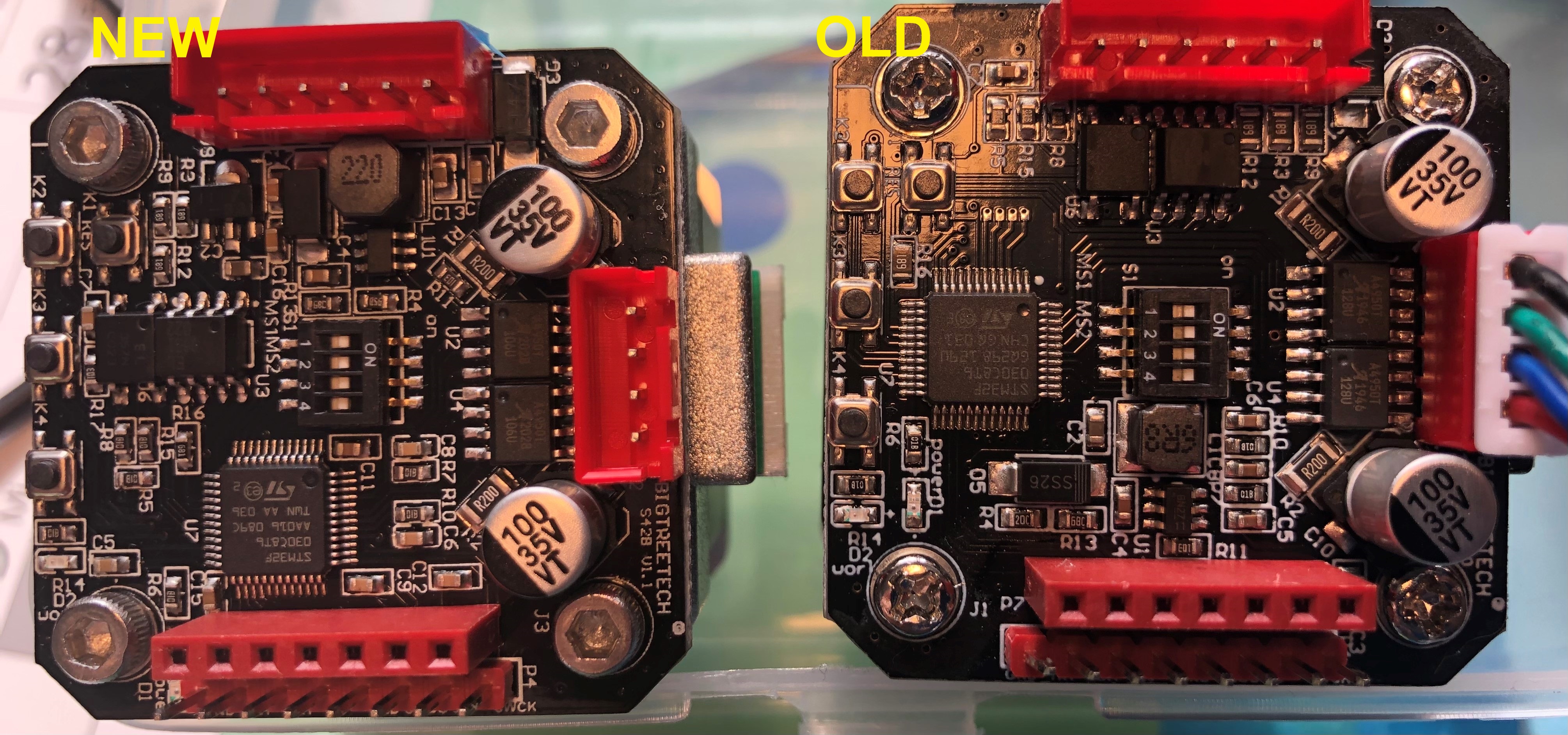
In the file oled.c, where the clock divide ration and oscillator frequency are initialized with the 0xD5 command. The parameter in the file is "80", but I think it should be the hex value "0x80". This might address some of the display instability issues.

swanepoeljan commented 3 years ago

You really are digging deep into this! It's great, almost wish my display also gave issues so that I can help with debugging :-)

Something else which could cause the jittery SPI signals are the interrupts. Maybe it's worth also trying to disable Timer6 (running at 10kHz) before the SPI transmission starts and enable it again after (create a critical section). Something like this:

void OLED_WR_Byte(uint8_t dat,uint8_t cmd)
{   
    uint8_t i;  
    LL_TIM_DisableCounter(TIM6);

        if(cmd)    
            OLED_RS_H; 
        else 
            OLED_RS_L;

    OLED_CS_L;        
    for(i=0;i<8;i++)
    {             
        OLED_SCLK_L;
        if(dat&0x80)OLED_SDIN_H;
        else OLED_SDIN_L;
        OLED_SCLK_H;
        dat<<=1;   
    }                
    OLED_CS_H;        
    OLED_RS_H;  
    LL_TIM_EnableCounter(TIM6);       
} 
swanepoeljan commented 3 years ago

I quickly fired up my BB60A spectrum analyzer with a H-loop antenna to repeat some of the EMI measurements you made:

10kHz to 2MHz with motor disabled: NFProbe_10kHz_2MHz_Disabled

10kHz to 2MHz with motor enabled: NFProbe_10kHz_2MHz_Enabled

The board is powered by 12V (do you also use 12V?) supply and the OLED removed to get in closer to the regulator.

I have only quickly glanced over the plots, like you also mentioned, looks like the regulator runs at about 450kHz to 460kHz. The noise floor also jumps up really high when the motor output is enabled. The interesting thing is that it's not constant over time, here is the waterfall display: NFProbe_10kHz_2MHz_Enabled_Waterfall

Can also be seen in zero span mode: NFProbe_ZeroSpan_1MHz Looks like its at 300ms intervals.

Quas7 commented 3 years ago

@swanepoeljan I am honestly impressed by your tool quality level here! :) And great to see, that my setup is somewhat showing at least a similar picture (just with far less resolution). BTW, the redpitaya stays on constant RBW for some reason (other FFT apps available but not tested yet). I just ordered a cheap tinySA to "compensate" for that in the future. ;)

I power my test setup with 12V as well. I also noticed a time dependency of the noise sources but the mech. load dependency was higher so I did not bother looking into it yet. These 300ms could even be linked to the update rate of the display as it looks like the same range.

I got my display now stable for over 16h straight with the fix in the PR - new record. And it really looks like there are two different failures involved that also show two different display errors (shifted lines vs. scaled&disturbed fonts). And I can now also provoke both failure pictures within 30min with F_OSC at certain levels or maybe just too low and also by adding NOPs at the wrong points in the SPI function.

Regarding the idea on disabling interrupts for SPI, I can imagine some random increases in the timing, if an interrupt is fired. I would try this next, if the display shows still issues. On the other hand, we could also just simply reset the display via the RST pin every ~1000ms and forget about it but I did not yet test, what an RST actually does to the display. ;P

caesar1111 commented 3 years ago

@Quas7 : sorry for coming back so late, but I had to get my Gartenzwerg ready for winter..... I finally got my 50cm jumper wires delivered. One stepper which had issues while the display was plugged in is now running flawless even for >24hrs. 1

The other stepper which was producing the black screen, is still having some issues, just with the 50cm wires, so I added some kind of choke which improved the situation, but is still producing artefacts after a few hrs. printing. 2

So I plan to design a mount to attach the display to the frame as far away from the stepper as possible. I will also replace the chokes with the the ferrite beads as soon as the shipment arrives. But while I am working on the hardware, I am happy to test different firmware version. Just send me the complete files of the source code where you applied changes (makes it easier for me to compile the test firmware). …since we have no lockdown in Bavaria so far, I will be on a business trip until Thursday, so I can start the testing again on Friday.

Quas7 commented 3 years ago

@caesar1111 as this is an open-source community there is no time pressure. :) You can grab the optimized code from my fork here: https://github.com/Quas7/BIGTREETECH-S42B-V1.0/tree/OLED_stability_optimization For me, that solved both kind of artefacts I encountered.

Stay safe and healthy on your biz trip! I also expect something partly lockdownish in Hessen/Frankfurt in the coming weeks.

caesar1111 commented 3 years ago

@Quas7: Hi, I was flashing your firmware yesterday didn’t solve the problem either ;( It was looking good first, but then a layer shift happened still showing the changing values, after that the display froze and after about 2h printing the display went black..... Hardware is currently 50cm jumper cable extended with 20cm, so the display is about 60cm away from the board.... I have the two homemade ferrite beads, but somehow its not solving the problem.... without thorough testing it somehow feels that is got a little worse than my old firmware… Next step will be flashing the board again with the original firmware and work with the professional beads….. see if I can solve it with hardware.. If you have other versions of your firmware which I should test, just let me know.

Quas7 commented 3 years ago

@caesar1111 Thanks for the testing and feedback. I also ran into one interlaced-screen error after approx. 40h sitting on my bench but without any extension cables or beads in place.

I will now just throw in an "init_OLED" every few 100k loops (~20sec) into the main routine to recover from any form of glitch. That is really not the best way of engineering but without having 10 DUTs or a very clever trigger to catch the issue it gets too time consuming to debug.

I updated my fork and the PR with this "fix". You can also change the re-init periode by changing the 100.000 in main.c line 669 to something else (just up to 4mio or change the variable type of OLED_reset_counter to 'long'). Edit: And I changed a few NOPs in the SPI function. So, you also try first to remove the OLED_init in the reset function to test the changed SPI interface only.

I think, the designers at bigtreetech also found this issue during development and could not resolv it as there is the following comment block in main.c ;P

//OLEDOK
//2019-10-21 
//2019-10-22 
//2019-10-23  
//2019-10-28
//2019-10-29 
//2019-11-02 
//2019-11-04  
//2019-11-07 
//2019-11-11 
//2019-11-15 
//2019-11-18 
//2019-11-19 
//2020-01-03 
caesar1111 commented 3 years ago

not even 70 cm cable with a ferrite ring is not solving the problem image still in contact with btt for a solution

caesar1111 commented 3 years ago

@nhabes79 : since you were also experimenting with the PID for a coreXY and the S42Bs installed for XY. have you already some good values to start with? While the BTT guys are letting me wait for solution I will haunt down PID values issues which is resulting in overshooting on edges at my printer. So your values would held while nailing down the correct values for my printer

Quas7 commented 3 years ago

@caesar1111 the OLED frequency will not solve this - there are other issues as well. I proposed a "fix" for the OLED issue in #20 This re-inits the OLED around every 60 seconds. For what the OLED is normally used, this should be sufficient in my opinion or you reduce the counter to re-init every 10secs but it blanks for 1 second.

caesar1111 commented 3 years ago

@Quas7: Problem is, if the stepper is idle you will loose the values when re-init. and it will not help with the sever cases, where the screen goes black withing 10 sec.... (I have one stepper who does that). Right now, the BTT support is digging down a faulty lot which was shipped out.... at least they asked me for my order number..... this indidcates a quality problem with might not be solvable with a software fix at all.... so currently the only way to get the OLED running without resetting it all the time is to use a long jumper calbe with ferrite beads to get the OLED away and stabilize the signal. To still get a decent display I had to alter the frequency. Problem is, that this altering is indivdual to every stepper since it is a non consistant issue through out the lot I have.... Therefore a many way to tune the frequency would help to dial it in for every controller individually....

swanepoeljan commented 3 years ago

@caesar1111 Out of curiosity, have you ever try the TrueStep firmware with the board where the screen goes black within a few seconds? I noticed that the original code that updates the values (Simp, Err, Deg) on the OLED is very slow (due to floating point math, etc.) and was wondering if it could affect the operation of the SPI bit-banging for the OLED. In TrueStep I cleaned it up a bit and would be curious to see if makes any difference.

Alternatively, in the original firmware when you are in the menu does it still go black? Since in the menu it would normally not run the code to calculate these values. Just poking in the dark :-)

swanepoeljan commented 3 years ago

Oh ja, something else I wanted to mention. I spoke with a guy that worked in the car industry and he told me that they always had to pull unused pins to ground through a resistor, this was to improved EMC performance. In cases where you can't modify the hardware anymore the recommendation was to make the unused pins outputs or enable the internal pull-up resistors. Maybe this is also something we can try, I will also add it to TrueStep. If it doesn't solve the issue then it's still good practice anyway ;)

caesar1111 commented 3 years ago

so to your first question. Yes, I am currently running your actual version of TrueStep. have to do some more durability testing though...... I will test it with the OLED directly plugged in which is creating the fastest results... and I will try if it makes a difference if you stay in the menu with a static display or if you are in values screen with constantly changing numbers..

Quas7 commented 3 years ago

what would be interessting is, if the issue also pops up in open-loop mode as well. I suspect that only the closed-loop calculations impact the software SPI implementation.

caesar1111 commented 3 years ago

@Quas7 will test this also.... right now I am running PID at around P70I10D70..... strange but this is closed to the open loop print where I have no overshoot.... ...I will plug in the displays directly, so I have the results within a shorter time ...

Quas7 commented 3 years ago

@Quas7: Problem is, if the stepper is idle you will loose the values when re-init. and it will not help with the sever cases, where the screen goes black withing 10 sec.... (I have one stepper who does that).

hmm, I think enabling the OLED updates also during idle would not be complicated. But 10sec are really too fast to go for the re-init idea. I use the display only for the menu but now I figured that I did not even test, if the menu items get reloaded without pushing any button. ;)

caesar1111 commented 3 years ago

@Quas7 ...ok here we go with the first test results with the OLED plugged in directly running the TrueStep firmware:

Quas7 commented 3 years ago

@caesar1111 alright. One last shot... could you post a picture of the boards especially the STM32 controller? This behaves so erratic that I almost suspect counterfeit stm32 hardware that is very common on bluepill dev boards etc

caesar1111 commented 3 years ago

image hope that's detailed enough as I can read: STM32F 030C8T6 AA094 079 TWN AA 02 ST So it looks like a https://www.st.com/resource/en/datasheet/stm32f030f4.pdf

Quas7 commented 3 years ago

here one of my boards for comparison.

rotated

What I see in a quick comparison:

at least the STM32 does not look like an obvious fake part github.com/keirf/Greaseweazle/wiki/STM32-Fakes

@caesar1111 is there any marking on the D5 diode as on mine with SS24? and do you reas S42B v1.0 on the board next to the motor connector?

swanepoeljan commented 3 years ago

Here is mine also for comparison. image

Quas7 commented 3 years ago

@swanepoeljan thanks! I had no chance to identify this 6pin DC/DC converter without nowing that only "BN" was the identfier. ;) I will google a bit more around this weekend.

caesar1111 commented 3 years ago

...it really looks like a mix and match thing they do with the components... I can see that no board of ours is alike. Diodes, inductors and ICs are not matching up. I will have a closer look on my other 4 boards and see if I have at least some consistency there…

caesar1111 commented 3 years ago

...here I got another example of a mix and match... some ICs are different... 124378830_2869431283287527_2122614624298095173_o

caesar1111 commented 3 years ago

@Quas7 and @swanepoeljan : I now checked all my 5 boards.. Bottom line: no more than 2 steppers are alike completely. The 3 I bought at Aliexpress from BIG TREE TECH CO.,LTD Store are performing a little better. the come with a TWN AA020 code on the STM32 (like Quas7) The 2 I bought directly form BIQU performing poorly, one so poorly, that after resetting the board, the OLED goes black within 2 secs. they come with ta CHN GQ031 code on the STM32 (like swanepoeljan). So this means the are definitely using different sources for the components like Taiwanese or Chinese chip manufacturers for the STM32. And not a nut to crack for you guys. The only board which runs almost flawlessly is the one where the 6R8 inductor is soldered in upside down. This one has a TWN AA020 marking. IMG_E2992 ...just let me know if you need the pics of the other boards as well...

Quas7 commented 3 years ago

Not sure, if this is a real indicator as ST has multiple packaging and test facilities so there should not be much difference in the controller, if they are genuine.

I would also expect especially during the covid supply chain crysis that some components got 2nd sourced as well. But I see nothing out of the ordinary for industrial or consumer products (this would not fly for med/mil/avionic or automotive, of course).

I still suspect the board layout with the buck converter close to the com header is giving the main issue depending component tolerances. Things like using a hairdryer on the board and testing "hot" (<85C) might change the failure occurence rate for non-failing boards. I can give it a try this weekend.

Quas7 commented 3 years ago

found our guy (via aliexpress "BNOG" search...): https://datasheet.octopart.com/AOZ1282CI-Alpha-%26-Omega-Semiconductor-datasheet-67314984.pdf image

It runs the PWM on 450kHz +/-90kHz as we measured. That range might explain, why different countermeasures work on different boards.

BTW, 220 on the inductance does not mean 220uH it is 22uH. Which also fits perfectly the firs page datasheet example: image

And the table fits the selected components... The 68C is a 49.9k and the 20C is 15.8kOhm image

I already know from the BTT SKR boards that they really like to use the datasheet examples as best practise.

Quas7 commented 3 years ago

If I find time this weekend I will heat one of my boards up and check if it fails more rapidly (not heating the OLED!). Secondly, I will place a simple resistive load on Vout (C2 is the output cap) of the buck and try to drive the coil to saturation and check for the OLED and maybe EMI. It should result in something like this or even worse: image

As a hardware fix, it might help to just add a second 0806 capacitor on top of C2 and maybe as well on C5 as the input buffer cap. If the trace from the power header to the other side of the board has a high parasitic resistance, their might be a chance of generating some ringing in the buck converter output, if a sudden load jump happens, e.g. when the STM32 does pull more power for some reason.

swanepoeljan commented 3 years ago

found our guy (via aliexpress "BNOG" search...)

Great found! You have a gift for sniffing these kind of things out! ;)

kablek commented 3 years ago

The only board which runs almost flawlessly is the one where the 6R8 inductor is soldered in upside downThe only board which runs almost flawlessly is the one where the 6R8 inductor is soldered in upside down

This is interesting and worth testing out. Maybe polarity of inductor matters noise-wise. I am looking into theory behind this.

of the buck and try to drive the coil to saturation

I believe we are trying to avoid saturation of the core. Even datasheet states saturation is not desired. Larger inductor is easyer to saturate, this might be why larger inductor (22uH) seems to perform worse than 6.8uH, but it is weird since board shouldn't draw THAT much current really. Still worth looking into issue.

Inductor package seems to be NR4018, quick search on mouser: https://eu.mouser.com/_/?keyword=NR4018 shows 22uH parts with rated current of 590mA and 6.8uH pars with rated current 1060mA

I will try to do some calculations according to datasheet of the chip. Just slaping capacitors on board isn't really necesarily solution...

From my calculations both inductor should work fine with DC/DC chip, but note that measurements in datasheets are made at 100kHz going above that frequency does black magic.

Quas7 commented 3 years ago

The only board which runs almost flawlessly is the one where the 6R8 inductor is soldered in upside down

This is interesting and worth testing out. Maybe polarity of inductor matters noise-wise. I am looking into theory behind this.

I would be very supprised if there is any polarity dependence or more precise winding orientation dependence that would matter for sub GHz noise figures. Not even save to assume that the marking is giving any orientation at all for the winding direction. ;)

Note, that 6R8 is one worst and one best board in our collection. My 220 boards are average with hours of flawless operation.

of the buck and try to drive the coil to saturation

I believe we are trying to avoid saturation of the core. Even datasheet states saturation is not desired. Larger inductor is easyer to saturate, this might be why larger inductor (22uH) seems to perform worse than 6.8uH, but it is weird since board shouldn't draw THAT much current really. Still worth looking into issue.

Correct, saturation is bad. And provoking failures is the key of debugging that is why one would overload or saturate the core here on purpose to find margins for a coarse tolerance calculation.

And clearly, for same form factor or same core geometry more windings saturate the core more easily. The inductor and diode current peaks are also much higher than the average dc current provided at Vout. But, the buck is also implicitly considering the inductance already as for 22uH it has to drive linearly less current into it to keep Vout constant compared to 6.8uH (energy stays almost the same). But driving more current gives more EMI. For smaller inductance one would normally increase the frequency to reduce the peak current again but that is not available for this very basic converter here. On top, a much bigger output cap helps stabilizing in load dump situations to compensate the bucks limited dynamic range given these saturation limits or the input supply limits (see below).

Inductor package seems to be NR4018, quick search on mouser: https://eu.mouser.com/_/?keyword=NR4018 shows 22uH parts with rated current of 590mA and 6.8uH pars with rated current 1060mA

I will try to do some calculations according to datasheet of the chip. Just slaping capacitors on board isn't really necesarily solution...

From my calculations both inductor should work fine with DC/DC chip, but note that measurements in datasheets are made at 100kHz going above that frequency does black magic.

For bad board designs adding caps piggyback is normally the best you can do. ;P For beefier buck converters it is even best practise for 4layer boards with dedicated power planes to have two different form factors for the buffer caps (electrolyte+kerko or 0603+1208) resulting in two different ESR and filter frequency response. In our case the very long almost unbuffered shared (!) supply wiring to this buck input is at least a not perfect condition in case of non steady load scenarios. There is not even a central >10uF cap to buffer the main power rail at the connector. ;)

Quas7 commented 3 years ago

Found some time to at least follow the supply voltage traces.

image

The buck converter is at the end of the complete chain. C3 has likely 220nF but it looks like there is only one cermamic buffering the two A4950 that is also a bit far away.

UPDATE: image image

I just loaded the buck with additional 100Ohm load (+33mA) and my display fails within seconds with skipped lines. Also I start to see random pixels as noise on the OLED. Increasig from 12V supply to 24V supply removed these pixels again - pixels vanish at 15V.

Adding 22Ohm and the display is black and everything gets unstable and I get big spikes on the Vout. Still, the multimeter shows 3.3V. ;)

Stock configuration (yellow Vout, green Vin): image

small spikes every 22us on the 3V3 line.

Added 100Ohm to add stable +33mA to Iout and I catched some events that might have killed the communication: skipped lines: image tall characters: image

I assume, the resulting error just depends on where the SPI communication is hit.

Looking at the LX node (here plotted in green) in parallel does not show a correlation. image

Now for possible simple fixes: Adding 10uF parallel to C3 does not help anything (at least not with a THT kerko). As the spikes do not originate from the LX node, I am not sure, if they do not result from something else, e.g. ground level shifting?

Adding a 10uF THT kerko parallel to C2 (output cap) with 100Ohm still in parallel removes all noisy pixels at 12V Vin (noise starts at 11V) and OLED stays stable. I assume, that with removing the 100Ohms we get sufficient margin for stable OLED. Switching from 100Ohm to 47Ohm results in the same OLED issues again even with the added 10uF.

The root cause for the 3V3 spikes is still unknown as the LX node does not show anything. Next would be to measure all 3V3 customers on the PCB or to find something that "ticks" with approx. 22us or around 45.5kHz (any known timers there?) If I do another debug session I will remove L1 and inject a clean 3.3V there to check for the spikes once more. But, that might have to wait a few more days or even weeks.

kablek commented 3 years ago

These are great findings! These seem to me like typical buck converter switching noise case (or perhaps ground line problems, but this will be much harder to diagnose or fix).

Adding 10uF parallel to C3 does not help anything (at least not with a THT kerko).

That again indicates the problem is with switching transients. I think it would benefit smaller low ESR/ESL ceramic capacitors, 10uF THT is just not going to help much in my opinion. Also there is more than enough capacitance from two big electrolitics, 10uF just wont do anything.

Adding a 10uF THT kerko parallel to C2 (output cap) with 100Ohm still in parallel removes all noisy pixels at 12V Vin

Again I would suggest going for smaller capacitance with low ESR, 10nF? I believe good idea would be to measure actual value of C2 since that is pretty much only real output capacitance. If it is small 100nF-ish capacitor, then we do need to add about 10uF, maybe even better 4.7uF tantalum - KEEP ESR/ESL LOW!

If C2 is one of those high capacity tiny capacitor (1-10uF ceramic tiny thing), which I doubt since they seem a bit expensive for putting on chinese mass produced cheap driver, then ESR/ESL is over the roof, then adding small 10nF-ish capacitor in paralel should help.

I did try random electrolitic capacitor I had laying around on OLED 3v3 pins, but of course, it is far away from source of noise and ESR values are not great, so it did not help at all.

Next would be to measure all 3V3 customers on the PCB or to find something that "ticks" with approx. 22us or around 45.5kHz (any known timers there?)

I don't believe it is anything STM operated, since removing all the functionality and code except OLED did not help the issues with OLED. A4950 do use fixed off time of typical 25us but, datasheet does state minimum and maximum times of 16us and 34uS. It should not do much when motors are of though. Might even be some timing thing inside OLED module.

If I do another debug session I will remove L1 and inject a clean 3.3V there to check for the spikes once more. But, that might have to wait a few more days or even weeks.

That will probably eliminate problems, and it probably would be most reliable solution to just throw linear regulator on instead of switching regulator. That is however a bit... hard to expect everyone to modify their boards to that extent. I will try to find some components and experiment with adding capacitors where I believe they are needed.

Quas7 commented 3 years ago

I would habe piggy packed 0806 but had no 10uF available. You can bet that the output cap is same as in the schematic above. Adding 100nF for the 100ns spikes makes sense.

If C2 is one of those high capacity tiny capacitor (1-10uF ceramic tiny thing), which I doubt since they seem a bit expensive for putting on chinese mass produced cheap driver, then ESR/ESL is over the roof, then adding small 10nF-ish capacitor in paralel should help.

what do you mean with "expensive"? Those 0806 kemet with 10uF are all <1cent parts in 10kpcs, if one does not need high voltage ratings. It is still a factor of 10 above a 100nF kemet but not expensive in my opinion. And it will not help as much as expected to improve ESL,if the design only has long traces everywhere and no power planes.

As can be seen above, a ultra high-ESL THT 10uF kerko already solves the issue with +33mA overloading. Next step would be to replicate this on 6R8 boards with 100Ohm load and 10uF

Solution for non-solder guys is hopefully buying v2. ;)

kablek commented 3 years ago

I hope V2 are better... unfortunately I do not have money to buy a set of V2 drivers so I am stuck with what I have. Thankfully I am very solder guy :D so I will have to do with what I have.

Shall I do some tracing back of connections maybe? it would be painfull job probably.

Can we identify cap that is on the board currently? Maybe measure it in circuit? and complement it with correct complementary capacitor? I should head to the basement on some further research on circuit board topology.

I will try some stuff, but I only have recycled parts at the moment since our country is in a lockdown.

EDIT: IDK WHAT I DID SUDDENLY ONE OF MY DRIVERS IS STABLE?!?! Okaj breatheeee.... So was trying to measure C2 in circuit with multi-meter -> no go. Then, I tried attaching 10uF electrolytic to C2 but I believe I mistakenly soldered 10uF across C4 which would be...bootstrap?... It made things worse firs but when I ripped the improvised capacitor out, it suddenly started working well (with my experimental code test)

Quas7 commented 3 years ago

@kablek there are not too many connections or components for the 3V3 so tracing should be job of 10 minutes, I hope. But all information is welcome, of course. :) BTW, I am really not sure, if adding 10-100nF on C2 helps much as I suspect the typial 100nF blocking caps on all of the Vcc IC pins. Just noticed, that the TLE5012 with its 12-16mA current consumption does not have the blocking capacitor on the back side - maybe it is attached on the top side or they simply omitted it. ;)

And the STM32 is capable to sink 120mA depending on pin switching. It is by far the biggest customer on the 3V3 rail and I did not yet beep out, if they added the datasheet advised 2x100nf+ 1x4.7uF to its VDDs.

I tried with a VNA and with my trusty multi to measure in circuit the impedance of the 3V3. No chance as the rail is just to leaky. Guess, you made the same conclusion in your edit above.

But, as stated already, BTT loves staying close to the datasheets and it most likely simply a 10uF.

Yes, C4 is the boostrapping cap for the NMOS gate driver.

My first guess would be, that the magic stability is some kind linked to a temperature effect that comes along with the soldering. Maybe you wait 10 min and retest, if it is getting unstable again and maybe just use a hair dryer as I intended before but just did not yet experimented with as I solved it brute force with 10uF already. ;)

kablek commented 3 years ago

Guys, we don't need to trace with multi meter and probing. Open repository file "Item-Pinmap.PDF" in PDF viewer that supports table of contents toolbar (I use SumatraPDF). Open up TOC, all the nets and pins on those nets are in TOC.

And yes C4 is bootstrap capacitor, and C2 is THE ONLY capacitor on 3v3 line!

Also note that there are pads for connections with PC14, PC15, PF0 and PF1 on the board.

I shall do some more investigation here :D

EDIT: also MOSI and MISO for magnetic encoder are connected together.

EDIT 2: There is begining of my reverse engineering altium project in my fork

caesar1111 commented 3 years ago

well I promised you the results of my tortoure testing....image ...after about 15hrs at 100mm/s even the best performing board failed and the OLED went black, the other just froze with artefacts..... and still no news from BTT which promised to send put replacement boards after sending a video to prove the problem...

Quas7 commented 3 years ago

Similar fix but a bit easier to apply https://youtu.be/6yggQ2xOTqc It gets more likely that not only the OLED gets issues with the bad 3V3 rail design... missing steps likely because of brown out and reboot mid print?

caesar1111 commented 3 years ago

@Quas7 so what capacitor you are suggesting? I will just solder it to the jumper wires for testing, since I am planning to to an angeled bracket for my display anyway.... nad I am waiting on some feedback from the printer facebook page for the PID setting using the S42B on a Z axis.....

Quas7 commented 3 years ago

normally, one would need 1x 4.7uF "global" +4x 100nF per pin of the STM32. The buck requires at least 10uF itself for stable operation. So, I soldered just one more 10uF accross the output capacitor of the buck converter and got it stable for now.

Therefore, with short leads a 10uF ceramic would be my first guess also for the pin header although @kablek had less success with that but he had only an electroylitc capacitor at hand that is not well suited to filter high frequency noise that we see here. You can add 10uF on both ends of the OLED wire extension as well.

caesar1111 commented 3 years ago

...finally. I got the replacement boards. As you can see, they changed the board layout, but still there are issues with the display, but way better than before (long term testing to be done).

S42B-oldvsnew

While installing the steppers on a new printer, I had to undergo the PID tuning again and found out that there is a new version of the https://github.com/swanepoeljan/TrueStep out there. Great job on that, makes using the S42B much easier.