bigtreetech / BIGTREETECH-SKR-mini-E3

BIGTREETECH SKR-mini-E3 motherboard is a ultra-quiet, low-power, high-quality 3D printing machine control board. It is launched by the 3D printing team of Shenzhen BIGTREE technology co., LTD. This board is specially tailored for Ender 3 printer, perfectly replacing the original Ender3 printer motherboard.
1.99k stars 1.98k forks source link

[BUG] Hotend mosfet not rated properly for BVDSS. #276

Open thebrakshow opened 4 years ago

thebrakshow commented 4 years ago

Description

While doing some validation of the mini E3V2 I noticed some nasty oscillation on the hotend mosfet drain pin. At first, I though it was a bit peculiar as I just assumed the hotend cartridge was basically a big resistor. Obviously there would be a bit of lead inductance but the oscillations wasn’t adding up to just a bit of parasitic inductance, so I measure the hotend. I found that there was ~1.3uH! This is a stock E3D V6 40W 12V cartridge. Below you can see what the drain pin looks like. The transition of the voltage going from low to high when the mosfet turns off.

SKRe3v2_12V_nodiode

Those voltage spikes are hitting just above the max BVDSS rating of the mosfets.

Now switching over to a 24V system things turn very ugly. Looking at the drain of Q1 we see a massive ripple once again. This pushes the drain pin of the mosfets over the rated BVDSS. In the capture below you can see the oscillation get clipped. This means the MOSFET has actually begun to avalanche and is acting as a zener... Now its not the end of the world to see a BVDSS break down every once and a while but on the E3 (V1-V2) its basically every cycle.

SKRe3v2_24V_nodiode

This kind of repetitive misuse of the mosfets will eventually lead to a catastrophic failure in which the mosfet fails shorted. I've been reading on several forms about mosfets failing (in general) on 3D printers and everyone is quick to blame the RDSon and over-temperatures of the mosfets. I'd be willing to bet more than half of those occurrences was actually due to this very issue. BTT please take note, anytime you switch something with an inductance you have to rate the mosfet with at least 2x the BVDSS rating compared to the voltage you are switching. So moving to a 60V mosfet will significantly help this situation. Also note, that by doing so you will not be getting rid of the oscillation, which if the mosfet is rated well enough, shouldn't be an issue. Alternatively, placing a well spec'd schottky diode in parallel to the device you are switching will provide a path for the currents to get shunted back to the source and eliminate the voltage spikes/oscillation. Which is what I have done below (cathode of diode to VCC, anode to switching side).

24V with Diode SKRe3v2_24V_diode

12V with Diode SKRe3v2_12V_diode

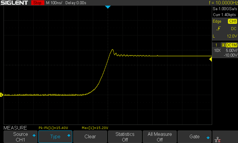
One can see that there is a tiny bit of overshoot but then the diode start conducting before it actually makes it too much above its respective VCC. In this case a fast switching diode is necessarily, so something like a 1N400X really isn't recommended. For this experiment I used a SB5100. I simply crimped it across the two hotend terminals. He is an example of what I did (not the actual heater cartridge used in this experiment):

diodehotend

This should be easy enough for people to add after the fact to protect their mosfets.

CAUTION: The orientation of the diode matters. The Cathode (or barrier bar) needs to be on the VCC pin. The anode needs to be on the switching (drain pin of mosfet) side.

FWIW, I am seeing this issue spread rampant across 3D printer motherboards from all vendors... please use your best judgement when printing for long periods of time. If you follow my advise on adding a diode, I am not responsible for any damaged caused by the modification :P

scintilist commented 4 years ago

This kind of repetitive misuse of the mosfets will eventually lead to a catastrophic failure in which the mosfet fails shorted.

This is not true if the device is operated in accordance with its specified avalanche limits.

The hot-end mosfet is the VS3060AD, which is rated for a single-pulse avalanche energy of 81mJ, and is also specifically rated for repetitive avalanche.

Avalanche failure is at its core a thermal failure, so as long as the single pulse energy and junction temperature limits are respected, there should be no problem.

Using your own measurements, the inductance of 1.3uH and a 40W 24V hot-end current of 1.67A will store an energy of 1.81uJ, which is the worst-case single pulse avalanche, and is 0.0022% of the datasheet limit.

In Marlin, the hot end PWM frequency is 7.6294 Hz, so the worst-case heating from the avalanche dissipation is 13.8uW, or basically 0.

This suggestion of adding a parallel diode is poorly informed and actually dangerous, since there is a real risk of fire if the used installs a high current diode backwards.

houseofbugs commented 4 years ago

This kind of repetitive misuse of the mosfets will eventually lead to a catastrophic failure in which the mosfet fails shorted.

This is not true if the device is operated in accordance with its specified avalanche limits.

The hot-end mosfet is the VS3060AD, which is rated for a single-pulse avalanche energy of 81mJ, and is also specifically rated for repetitive avalanche.

Avalanche failure is at its core a thermal failure, so as long as the single pulse energy and junction temperature limits are respected, there should be no problem.

Using your own measurements, the inductance of 1.3uH and a 40W 24V hot-end current of 1.67A will store an energy of 1.81uJ, which is the worst-case single pulse avalanche, and is 0.0022% of the datasheet limit.

In Marlin, the hot end PWM frequency is 7.6294 Hz, so the worst-case heating from the avalanche dissipation is 13.8uW, or basically 0.

This suggestion of adding a parallel diode is poorly informed and actually dangerous, since there is a real risk of fire if the used installs a high current diode backwards.

The MOSFET on the SKR E3 Mini V2 that I have is the WSF3085, not the VS3060AD. Here is the datasheet on the WSF3085: https://datasheet.lcsc.com/szlcsc/WSF3085_C148428.pdf

I'll see if I can replicate the data with a 40W heater at 24V that @thebrakshow posted using my DS1054Z and report back in a few days. But mosfets should have a diode across their output for this exact reason reason. Not sure why they aren't installing them (aside from cost cutting) on their boards but it would make them more reliable and less prone to failure having a diode there to prevent the oscillation since it is driving this type of load. Here is a good video explaining why you should have one when using a MOSFET: https://www.youtube.com/watch?v=Aqng4sXIl3Q

20200525_132739

houseofbugs commented 4 years ago

This what it looks like when it shuts off. I'll do the on testing in a bit. Tested at 24V input and 40W heater. Its better with a diode (as expected) but not seeing it go outside the rating of the MOSFET.

Stock: NewFile2

With 1N5822 Fitted (all I had laying around): NewFile3

houseofbugs commented 4 years ago

Turning on with 24V 40W heater and 24V input. Aside from some oscillation on the off the on doesn't look too bad and is in spec for the FET. BVDSS for the WSF3085 is 30V which I am not seeing it exceeding. Maybe @thebrakshow got a bad fet?

A diode would help prolong the life of the FET but I am not seeing it go outside of the specs for the fet datasheet for the WSF3085.

Stock: NewFile4

With 1N5822 Fitted (all I had laying around): NewFile1

houseofbugs commented 4 years ago

For comparison here is another brand of board with the same 24V 40W load when the fet is switching on and off:

Turning on: DS1Z_QuickPrint2

Turning off: DS1Z_QuickPrint3

MarcPot commented 4 years ago

So the people in this issue do not agree on the point about the mosfet. You seem to agree on that adding a diode would have a positive effect though it could be dangerous to add it.

For someone less inclined with electrical engineering but knowing left from right. How fast would the result of adding the diode the wrong way appear? The moment you turn on the mosfet, or could it happen at any random moment?

Or could I just use a multimeter to check if it’s positioned right before I turn it on.

Also would having a “bad” diode result in danger or would it simply have no effect at all?

The diode fix seems simple enough to do anyways, no matter who’s right. Just like to do it the right way.

scintilist commented 4 years ago

Here is a good video explaining why you should have one when using a MOSFET: https://www.youtube.com/watch?v=Aqng4sXIl3Q

That video does not apply here. Driving an inductive load with the bed or hot end output would be a complete misuse of the board. There would be no harm to adding a parallel diode at the factory aside from the board area and cost constraints, but it will not increase reliability if the board is used as intended to drive resistive heater loads. The small amount of lead inductance does not make this an 'inductive load' requiring diode protection, as you can see in my previous calculation of how far below the rated avalanche energy this is.

By definition, whenever avalanche occurs you will have exceeded the voltage rating of the mosfet and it will show up in your scope captures. Operating in avalanche is just another region of operation for a mosfet and is not a 'failure' unless you exceed the rated avalanche energy.

The Vds scope captures only show whether it is operating in avalanche at all, but do not provide any information about the actual avalanche energy.

Using a scope incorrectly with too large of a ground loop, and/or improper compensation can also lead to the appearance of large overshoots where none exist in reality. This would explain the large difference between what @houseofbugs and @thebrakshow are seeing.

Also note that my previous calculation of the maximum possible avalanche energy assumes instantaneous turn off of the mosfet, and 100% of the stored energy being dissipated as avalanche current (this is an over-simplified worst-case). The reality is that gate capacitance and gate driver output resistance slow the turn on/off times, allowing most or all of the stored energy to dissipate resistivity during turn off before any avalanche can occur.

houseofbugs commented 4 years ago

Here is a good video explaining why you should have one when using a MOSFET: https://www.youtube.com/watch?v=Aqng4sXIl3Q

That video does not apply here. Driving an inductive load with the bed or hot end output would be a complete misuse of the board. There would be no harm to adding a parallel diode at the factory aside from the board area and cost constraints, but it will not increase reliability if the board is used as intended to drive resistive heater loads. The small amount of lead inductance does not make this an 'inductive load' requiring diode protection, as you can see in my previous calculation of how far below the rated avalanche energy this is.

By definition, whenever avalanche occurs you will have exceeded the voltage rating of the mosfet and it will show up in your scope captures. Operating in avalanche is just another region of operation for a mosfet and is not a 'failure' unless you exceed the rated avalanche energy.

The Vds scope captures only show whether it is operating in avalanche at all, but do not provide any information about the actual avalanche energy.

Using a scope incorrectly with too large of a ground loop, and/or improper compensation can also lead to the appearance of large overshoots where none exist in reality. This would explain the large difference between what @houseofbugs and @thebrakshow are seeing.

Also note that my previous calculation of the maximum possible avalanche energy assumes instantaneous turn off of the mosfet, and 100% of the stored energy being dissipated as avalanche current (this is an over-simplified worst-case). The reality is that gate capacitance and gate driver output resistance slow the turn on/off times, allowing most or all of the stored energy to dissipate resistivity during turn off before any avalanche can occur.

The PSU I was using is on an isolation transformer with no earth ground passed through. But I am not seeing what the OP was saying. It's not super smooth on the off but its not out of spec, at least on the board I have here.

zbrozek commented 4 years ago

Unclamped inductive overshoot can't be more than 2x the supply voltage, indicating something wrong with the probesmanship in the first plot.

VinnyCordeiro commented 3 years ago

Unclamped inductive overshoot can't be more than 2x the supply voltage, indicating something wrong with the probesmanship in the first plot.

I beg your pardon, but you are wrong. The induced voltage depends only on the magnetic field of the inductor, not on the power supply voltage. Dave Jones released a video today showing exactly that.

zbrozek commented 3 years ago

You're right; I didn't quite say what I meant and was thinking about the case where an LC is driven from a step function. The voltage across C will peak at twice the steady-state voltage of the source. Of course with arbitrary current in an inductor we can cause an arbitrarily high voltage when opening the circuit. Playing around with a simulation of a DCM boost is a nice way to see it.