 EFeru
commented
5 years ago
EFeru
commented
5 years ago Nope, stock 16 kHz. I did try also 20 kHz, but same behavior.
Edit: Still wonder why changing the order gives wrong readings.
Open btsimonh opened 5 years ago
EFeru
commented
5 years ago Nope, stock 16 kHz. I did try also 20 kHz, but same behavior.
Edit: Still wonder why changing the order gives wrong readings.
 TomTinkering
commented
5 years ago
TomTinkering
commented
5 years ago Hmm I would have to dive into that. What happens if you just change the order of the two phases?
EFeru
commented
5 years ago Just tried... Wrong ADC reading again... motor starts spinning without my will. Apparently only the default order works. Is there a mapping somewhere that we miss?.. because this is really strange behavior.
 lalalandrus
commented
5 years ago
lalalandrus
commented
5 years ago Order affects the memory locations. Are you reading the right index in the array ?
EFeru
commented
5 years ago Which array? :)
lalalandrus
commented
5 years ago I am on my phone but I think it is add.buffers the names should be referencing a index into that but I can't check if it is a struct or otherwise as I can't search
EFeru
commented
5 years ago I am on my phone but I think it is add.buffers the names should be referencing a index into that but I can't check if it is a struct or otherwise as I can't search
It is a struct
typedef struct {
  uint16_t rr1;
  uint16_t rr2;
  uint16_t rl1;
  uint16_t rl2;
  uint16_t dcr;
  uint16_t dcl;
  uint16_t batt1;
  uint16_t l_tx2;
  uint16_t temp;
  uint16_t l_rx2;
} adc_buf_t;
But how does it know which one is which on ADC channel? I can't figure it out.
lalalandrus
commented
5 years ago The rank determines the order. It is a memory copy into the struct. The struct order should match the adc order
 p-h-a-i-l
commented
5 years ago EFeru
commented
5 years ago
p-h-a-i-l
commented
5 years ago EFeru
commented
5 years ago I have to look into it how this works because it is not very clear to me. Just that is getting late here, so I have to resume tomorrow.
EFeru
commented
5 years ago @lalalandrus I tried with correct mapping in adc buf, still the ADC read is not OK. I have to still look in the implementation from @p-h-a-i-l If you have time to play with the code, is here: https://drive.google.com/open?id=1asDxM8wxEQCHfyMJi1apdlzu5Pmkqlf- I will make a repo later. Just do not go to Max because it might get stuck in Max speed due to clamping circuit on PI control which I need to fix. Edit: Only the long wire motor will spin.
EFeru
commented
5 years ago You can see a small negative dip right at the edge when the lowside mosfet is switched ON. Also, all PWM channels are in sync and both ADCs are setup to first sample motor A, and then motor B. This means that there is a good chance for motor A that you might be sampling right on the edge of this dip. Especially at higher currents this dip will be more pronounced and potentially cause more problems.
@TomTinkering , you might be right. One thing I forgot to mention yesterday is that the RIGHT motor (short wired) current measurement has more spikes on it because is measured first compared to the LEFT motor (long wired), You can see it also on the figure from me in a comment above. So, I tend to think that we are indeed on that negative dip.
Then 2 things come into my mind:

 btsimonh
commented
5 years ago
btsimonh
commented
5 years ago from memory: ADC1 and ADC2 are linked (ADC_DUALMODE_REGSIMULT?). one fills out the 'left' side of the 32 bit numbers, the other the 'right' side. i.e. we DMA 5 longs, each of which contains one ADC1 reading, and one ADC2 reading, which end up as a pair of shorts in our structure. (these are assumptions from reading the software, and a quick look at the STM docs...). I ASSUME that ALL ADC reads are triggered at the same time by TRG0, and that the DMA will occur when all reads are complete (i.e. when the temp reading is complete, because this is slower?). Note how in bldc.c, I change the buffer it will use next, so keeping (10?) results - the latest is in:
volatile adc_buf_t *buf in the DMA interrupt.
It does sound like we are sometimes sampling in dead time.
because is measured first
Do we think ADC happens in a sequence, or are all at the SAME time?
Also, look at my brief writeup on deadtime: https://github.com/bipropellant/bipropellant-hoverboard-firmware/wiki/Notes-on-BLDC-Drive-and-Hoverboard-motors
Here I highlight that the drive to the PWM may need to be modified to include a pedestal near zero crossing (OF THE CURRENT). Note how, because we are star (Wye) connected, the current is:
Iuv = 0;
if (u-v-d > 0) Iuv = u-v-d;
if (u-v+d < 0) Iuv = u-v+d;
i.e. without adjusting u-v-d to > 0, or u-v+d to < 0, at least one of u and v is undriven because of how the deadtimes of u and v interact.
deriving an equation for what u and v should be for a desired Iuv was beyond my small brain :). BUT - this lead me on to think about 'what if we kept one phase at -1000' - i've seen this in some of the papers on BLDC control. Can we get sinusoidal currents driving only 2 phases (maybe swapping the phases we drive according to hall location?), and does this make everything a little easier, and is the fact we only have current sense on two phases a clue to this being the design spec for the hardware?
Edit:
What is a proper way to change the order of ADC ranking?
Double check the STM documentation. Does the ranking affect the time of sample, or is all sampling started at the SAME time, and the ranking only affecting memory position? - check you are not chasing wild geese... :).
EFeru
commented
5 years ago Double check the STM documentation. Does the ranking affect the time of sample, or is all sampling started at the SAME time, and the ranking only affecting memory position? - check you are not chasing wild geese... :).
I checked https://www.st.com/content/ccc/resource/technical/document/application_note/c4/63/a9/f4/ae/f2/48/5d/CD00258017.pdf/files/CD00258017.pdf/jcr:content/translations/en.CD00258017.pdf Page 9, Dual regular simultaneous mode
So we are in Simultaneous mode
multimode.Mode = ADC_DUALMODE_REGSIMULT;
Both ADCs should start and end in the same time. Changing rankins should not affect the total time.
btsimonh
commented
5 years ago but also, each set of 5 conversions occurs serially... :). so ignore all my 'same time' s**t above...
edit: I don't think we calibrate the ADCs. May be worth considering if we're going to use them seriously. Not sure what the internal calibration adds over the 'offset' calculation though... and certainly not your issue.
edit2: the docs explain the software trigger set:
In dual mode, when configuring conversion to be triggered by an external event, the user must set the trigger for the master only and set a software trigger for the slave to prevent spurious triggers
edit3: note the 'same sample time' requirement for ADC1 & 2 when in dual mode - i.e. if orders are changed, make sure the sampling time for each sequential read is the same in ADC1 & ADC2.
EFeru
commented
5 years ago edit3: note the 'same sample time' requirement for ADC1 & 2 when in dual mode - i.e. if orders are changed, make sure the sampling time for each sequential read is the same in ADC1 & ADC2.
Yes, I did make sure when I changed the order, otherwise would be a mess.
Another thing, I found here that the Center aligned TIMER can trigger interrupt in both overflow and underflow. See here: https://community.st.com/s/question/0D50X00009Xke44SAB/interrupt-in-overflow-event-of-timer-in-updown-mode Maybe, we have the same issue.
EDIT1: Also here
https://www.waveshare.com/wiki/STM32CubeMX_Tutorial_Series:_Basic_Timer
In center-aligned mode, the counter counts from 0 to the auto-reload value (content of the TIMx_ARR register) - 1, generates a counter overflow event, then counts from the auto-reload value down to 1 and generates a counter underflow event. Then it restarts counting from 0.
EDIT2: Do we need to change some REGISTER settings? (Because the original repo was written for 6 step Commutation motor control)
Bellow I found some register settings for sinusoidal control. And now we do Sinewave control.
http://d1.amobbs.com/bbs_upload782111/files_10/ourdev_265522.pdf
Page 11

btsimonh
commented
5 years ago reviewing
http://vocke.tv/lib/exe/fetch.php?media=20150722_hoverboard_sch.pdf
seems the phaseA and phaseB inputs are the wires to the motors, not measurements of shunts to gnd. Whereas the DC current value is a shunt. Your 'near 0' indicates -ve bat on these lines.
As @TomTinkering highlighted, to use these to measure current, we are using the on resistance of the mosfet as the measurement device. Maybe they are intended to measure backemf voltage, not current? - not sure what currents your values represent, but they are fairly small numbers (only +- 100 from the 2000 center?), so that may indicate that the hardware is tuned to reading backemf.
You are monitoring adc_buffer? in the current firmware, this is populated by a memcpy only done every 5ms (in readADCs() called from main).
For a truer result, you should probably make your own copy from
volatile adc_buf_t *buf in the DMA interrupt.
At the moment, I can't understand why using the copy would give you zeros....
IF you are using OLDER firmware, and monitoring adc_buffer, not a copy, then unless MAX is synchronised with the DMA, then it could be that the DMA clears the values as it writes in some way (the older firmware DMAed direct to adc_buffer?). It may even be that memcpy clears the destination, so maybe try a 'manual' copy setting new values to monitor by direct assignment?
EFeru
commented
5 years ago not sure what currents your values represent, but they are fairly small numbers (only +- 100 from the 2000 center?), so that may indicate that the hardware is tuned to reading backemf.
That is because I used my hand to create some load. So, I could not put too much breaking torque, thus small currents.
At the moment, I can't understand why using the copy would give you zeros.... IF you are using OLDER firmware, and monitoring adc_buffer, not a copy, then unless MAX is synchronised with the DMA, then it could be that the DMA clears the values as it writes in some way (the older firmware DMAed direct to adc_buffer?). It may even be that memcpy clears the destination, so maybe try a 'manual' copy setting new values to monitor by direct assignment?
Can you give an example how to do that? This low level register, timer , ADC reads are a bit out of my capabilities. EDIT: I use the configuration from the orginal repo from Niklas.
EFeru
commented
5 years ago This file needs to be reviewed: stm32f1xx_hal_adc_ex.h
EDIT: Can't we ask some STM guy to check if the settings are correct?
btsimonh
commented
5 years ago if this is the base bldc.c:
https://github.com/EmanuelFeru/hoverboard-firmware-hack/blob/master/Src/bldc.c
then try:
at top of file:
volatile adc_buf_t adc_buffer_copy = {0};in DMA interrupt:
memcpy(&adc_buffer_copy, &adc_buffer, sizeof(adc_buffer_copy));then monitor adc_buffer_copy
also note that if MAX uses breakpoints, or pauses the MCU to make readings, the PWMs may get disabled in these times in hardware as a protection mechanism - i.e. if MAX reads at the ADC sample time, you may see odd things - IF MAX Pauses the MCU.
I was readying some logging of u/v/w+currents to RAM, then read over serial, but not done yet. Thought it may be a useful 2nd route to 'seeing' the values. Reading that PDF, seems one option they do use for debug is to drive a DAC from the values, so you can literally 'scope' them - e.g. you could try setting the LED GPO to be a DAC output, and write the a current to it, then you'd see the current you read/'scope as a signal on the LED?
EFeru
commented
5 years ago @btsimonh , I will try that tonight
also note that if MAX uses breakpoints, or pauses the MCU to make readings, the PWMs may get disabled in these times in hardware as a protection mechanism - i.e. if MAX reads at the ADC sample time, you may see odd things - IF MAX Pauses the MCU.
Quick question, which MAX are you refering to?
EDIT1: Also the CubeMX creates 2 additional functions in ADC
void HAL_ADC_MspInit(ADC_HandleTypeDef* adcHandle)
void HAL_ADC_MspDeInit(ADC_HandleTypeDef* adcHandle)
See in the CubeMX project from @AntumArk: https://github.com/AntumArk/HoverboardMX/blob/5a540967a8d46cc16b628668aa4f07f861b04dda/Src/adc.c#L145-L146 We do not have them in the original repo. Those functions are not needed?
PS: Sorry, for spaming... The reason I am insisting is because it would nice if we can find the issue to be able to continue with FOC.
btsimonh
commented
5 years ago Sorry, I thought STM Studio was called MAX for some reason, apologies...
Also the CubeMX creates 2 additional functions in ADC
i think it's covered in what we do already.
EFeru
commented
5 years ago Sorry, I thought STM Studio was called MAX for some reason, apologies...
No problem :) I did try with logging off (STM Studio disconnected), but same behavior. No change. The spikes are still there because I can hear them when the motor spins at high speed and the spikes become larger. High spikes -> high error -> Command of PI controller affected I had to put the gain Kp = 0 in the PI controllers of FOC, to avoid big errorneous commands. No gain == "Pain" (or bad control) :)
EFeru
commented
5 years ago @TomTinkering Can you please do one more measurement with the oscilloscope? To check that the DMA interrupt happens in the middle of the MOSFET conduction period.
You can do that by toggling the LED pin in the DMA interrupt: ->place HAL_GPIO_TogglePin(LED_PORT, LED_PIN); in bldc.c inside DMA1_Channel1_IRQHandler() Then, then put one oscilloscope probe on the LED PIN and one on the ADC phase current as you did before. For this a 2 channel oscilloscope is needed, I have only one.
Ideally, measure at stand still and moving wheel, to compare them.
EFeru
commented
5 years ago No wonder the values are wrong at higher speed.
I did current measurements on the Analog input PA0 pin, similar to what @TomTinkering did, but also during spinning motor.
As you can see it looks quite messy, there is no clear current measurement window. STM documentation says there should be a flat area created in the PWM signal for current measurement. However, I don't see it. So, I think the PWM generation/TIMER settings are NOT ok.
Do you have any idea why this behavior?

EFeru
commented
5 years ago ..... And this is the measurement from the Stock Factory on the un-hacked GD32 board: It is clear that they always create a measurement window.
Can you help me create that window in our software too?

TomTinkering
commented
5 years ago @EmanuelFeru I would love to help but don't really have time until thursday evening. As for the "measurement window", that is just the time where the low side FET is on. If you want this time to be longer, I think you can just change the CLAMP values to set the minimum and maximum duty cycle :
RIGHT_TIM->RIGHTTIM[X] = (uint16_t)CLAMP([xx] + pwm_res / 2, 10, pwm_res-10);
10/2000 = 0.5%, so this allows duty cycles between 0.5% and 99.5% which is quite close to the limits. I give no warranties, but 5-95% should be fine I think. So:
RIGHT_TIM->RIGHTTIM[X] = (uint16_t)CLAMP([xx] + pwm_res / 2, 100, pwm_res-100);
TomTinkering
commented
5 years ago @EmanuelFeru Some other thoughts, although they need to be verified: Timer is set to center-aligned. I think this indeed means that the ADC trigger happens in the middle of the ON time of the low-side fet. I will check this when I get the chance.
If that is true, we need to think about the ADC sample times:
RIGHT_TIM->RIGHTTIM[X] = (uint16_t)CLAMP([xx] + pwm_res / 2, 160, pwm_res-160);
Not sure if this will solve the issue in general, but it might solve the issue getting worse at high speeds.
EFeru
commented
5 years ago Putting the clamp to 100 helps a bit. RIGHT_TIM->RIGHTTIM[X] = (uint16_t)CLAMP([xx] + pwm_res / 2, 100, pwm_res-100);
I think, we need to do smarter things here. There is a DC link current for each motor. Why whould they put in an aditional OpAmp just for fun? For overcurrent protection.. I don't thinks so. If you look at what they did on the YST board... its incredible how much they cut down the costs there. But still they did not remove the DC link current measurement.
Don't they maybe use the DC link current to reconstruct the phase current (when measurement is bad), some sort of sensor fusion to have a more clean and accurate phase current? Probably yes.
 AntumArk
commented
5 years ago
AntumArk
commented
5 years ago Have you tried looking into ST libraries for FOC ? https://www.st.com/content/st_com/en/support/learning/stm32-education/stm32-for-motor-control-/pmsm-motor---foc-control.html They have recently started making evaluation kits for them, and created software for it. https://www.st.com/en/embedded-software/x-cube-mcsdk.html If it generates code, maybe we can analyze it? For example FOC firmware library http://www.emcu.it/STM32/STM32-MotorControl/f0g.png
EFeru
commented
5 years ago Yes, I did look into their code. And like with every code it is not easy to understand someone else implementation because the implementation documentation is missing and some key parts of the implementations are encrypted into *.lib files. On the other hand our system is a bit different with 2 shunt measurements and 1 DC link. They have 3 shunt measurements option or 1 shunt (which is patented) option. Of course, I try to extract and learn from their implementation too.
AntumArk
commented
5 years ago Ech... companies....
TomTinkering
commented
5 years ago @EmanuelFeru and everyone interested. I finally found the time to look into the timer/adc setup. I'll try to explain it in a few words, and then finish off with a measurement that validates it :)
Both timers are setup center-aligned, meaning, the first count up to a given value (in our case ~2000), then count down again. Whenever the counter reaches the PWM value we set, the output toggles high or low depending on the channel settings. In effect, this means that the PWM pulse is centered around the highest value of the counter (hence centre-aligned), but more importantly, it means that the timer update events occur exactly in the middle of both the HIGH and LOW part of the PWM cycle.
TIM1 is set to send a trigger to TIM8 when enabled, so they both start at the same time
TIM8 is set to send a trigger on each update event. This trigger starts the ADC conversion.
TIM8->RCR is set to 1, effectively meaning only the update event in the middle of the low-side FET on period is enabled (ask me for details if you want to know more).
The ADC is configured using DMA, and the BLDC controller is run in the DMA interrupt.
All this effectively results in ADC sampling right in the middle of the low-side FET ON period, followed by a DMA transfer and interrupt that contains the BLDC controller just as we want it.
This can be seen in the following image:

Now i can foresee two issues with this:
TomTinkering
commented
5 years ago @EmanuelFeru
Don't they maybe use the DC link current to reconstruct the phase current (when measurement is bad), some sort of sensor fusion to have a more clean and accurate phase current? Probably yes.
The YST boards don't have this opamp anymore. I think they probably used this for the balancing controller as it gives you some information on the motor torque. But since the YST board that I have doesn't use this anymore, I don't think it's critical for the motor control
I think the smart thing to do, is to filter the ADC values. We effectively sample at 16KHz, which is quite fast. This means we can do two things; either use a low pass filter and introduce phase shift, or average a fixed number of samples into 1 sample (8 sample avg for instance), and run the current control loop at 2KHz. This should already help you a lot. Also removing unrealistic outliers before averaging might improve this.
btsimonh
commented
5 years ago A few general questions for us all: 1/ Can we confirm that an original firmware runs at 16khz for PWM?
2/ What would be the effect of dropping to 8khz, so doubling the time we have to do everything?
3/ should we attempt FOC only for a range of speeds; i.e. at low/mid speeds, use FOC with limited PWM - If we go above a certain speed/torque demand, change to a scheme which does not need the ADC?
4/ @TomTinkering - the image above indicating the end of ADC/start of DMA interrupt is to the and of ADC including the temp measurement, correct? So the motor ADC measurements are complete in (7+7+13)/(7+7+13+13+237) of the period shown above? Maybe confirm if you are still setup by changing both ADCs to read only 3 values? (note- would disable poti control, so depends on ho you are making the wheels spin).
EFeru
commented
5 years ago @TomTinkering ,first of thanks for the nice work and explanation! It is very helpful.
Few remarks:
@btsimonh
A few general questions for us all: 1/ Can we confirm that an original firmware runs at 16khz for PWM?
The answer is Yes. I checked it the motor phase PWM the other day with the oscilloscope. Pulse period of about 62 - 63us, so around 16 kHz on the factory firmware.
2/ What would be the effect of dropping to 8khz, so doubling the time we have to do everything?
Hmm.. I would not do it. Because we will have too less points to approximate the sine wave in the high speed regime. Of course, we can try and see the effect and if it is acceptable.
3/ should we attempt FOC only for a range of speeds; i.e. at low/mid speeds, use FOC with limited PWM - If we go above a certain speed/torque demand, change to a scheme which does not need the ADC?
It can be an approach to take if we have still issues on high speed.
we know when the readings WILL be wrong - when the Low FET is not ON in the measurement period - so we KNOW which samples to ignore/interpolate! Just look at the last PWM value for the relevant phase, and if over a certain value, set the measurement to 0, and interpolate later! - Then we can use the full range of PWM? (@EmanuelFeru - or just set to the last value measured for quick and dirty theory test?)
I was thinking the same. But how to check the low FETs are NOT on? in order to do some manipulation.
btsimonh
commented
5 years ago I was thinking the same. But how to check the low FETs are NOT on? in order to do some manipulation.
they will not be on if the previous PWM value for that phase is set to turn them off before the measurement would be finished :). so basically 'if final PWM value < 160 then use last valid ADC value' (need to work out if you need to check for both low and high values.... i.e. <160 or >(2000-160) - i'm sure it will only be ONE of these....)
TomTinkering
commented
5 years ago A few general questions for us all: 1/ Can we confirm that an original firmware runs at 16khz for PWM?
Yes, and we should. This is the frequency (or at least in the range of) that the motor is designed for
2/ What would be the effect of dropping to 8khz, so doubling the time we have to do everything?
You don't have more time by reducing the PWM frequency, but you could get more time by reducing the BLDC controller frequency. However, currently we can take twice as long and still be on time. Changing the PWM frequency is dangerous, as if you go to low, the motor will act as a short-circuit and potentially fry your board. Going any higher would reduce the achievable motor current.
3/ should we attempt FOC only for a range of speeds; i.e. at low/mid speeds, use FOC with limited PWM - If we go above a certain speed/torque demand, change to a scheme which does not need the ADC?
@EmanuelFeru?
4/ @TomTinkering - the image above indicating the end of ADC/start of DMA interrupt is to the and of ADC including the temp measurement, correct? So the motor ADC measurements are complete in (7+7+13)/(7+7+13+13+237) of the period shown above? Maybe confirm if you are still setup by changing both ADCs to read only 3 values? (note- would disable poti control, so depends on ho you are making the wheels spin).
Yes this is the end of all ADC conversions. I don't understand your calculation? Basically there are two ADC's sampling in parallel, taking samples at sample times of 7/13 or 237 ADC clock cycles. The ADC clock is 8MHz (not MSPS :)), so the time it takes for the conversions is easy to calculate. Although thinking about this, this might be just the sample time, the conversion will then also take nrBits*ADC clock cycles, so it might take longer than I expect. I will look into this
IDEA we know when the readings WILL be wrong - when the Low FET is not ON in the measurement period - so we KNOW which samples to ignore/interpolate! Just look at the last PWM value for the relevant phase, and if over a certain value, set the measurement to 0, and interpolate later! - Then we can use the full range of PWM? (@EmanuelFeru - or just set to the last value measured for quick and dirty theory test?)
True, but better to just avoid such short duty cycles I think. They typically introduce more noise than do any good.
The measurement you took is at standstill? Because it looks like ADC read takes quite some time and there is little time left before the the FETs go high.
The ADC time you see is for all the values. The biggest influence here is the temperature with a sample time of 237. The only measurements that are affected by the PWM phase are the current measurements of the motor phases, the only take ~3us in total, and start right at the start of the ADC conversions.
Is there a way to reduce the time for the ADC read? By sampling the temperature and Vbat, all the slow stuff, separately? and leave only the currents read in the critical path.
Not really, you only have 2 ADC's to play with, but it is also not necesarry as explained above.
Also @btsimonh mentioned something related to this on point /4 And thinking out loud.. can we even start the ADC a bit earlier of the PWM counter overflow to gain some time?
Yes and no, technically we can setup the PWM differently to trigger at the falling edge, then start a timer, and use the timer to trigger the ADC's. This way you can control when the samples are taken in respect to the falling edge. However, I don't think this is necessary. Just don't go outside of 8-92% duty cycle.
YST board: yes, you are right, they removed the DC link op amp on YST board. That board is completely shaved.. they almost deliver only the PCB.. haha, I don't know how robust is that board.
Yeah it's impressive. Although I would say the quality is better than the STM32 board I had. It just doesn't have anything you don't absolutely need.
TomTinkering
commented
5 years ago As a general comment. I really think filtering is the way to go. That is the first step to any reliable measurement. For the temperature and DC current simple filters are already implemented in the current firmware, we just need to design a proper one for the phase currents.
@EmanuelFeru do you have any specs on the controller frequency you need? Can we run the BLDC control at say 2 or 4 kHz? Would phase shift be a problem for the control?
I can implement a simple filter to experiment with, although since you are using Simulink, it is probably much easier to design an test it there.
EFeru
commented
5 years ago Thanks for the answers! Regarding the controller frequency. For FOC:
Regarding the filtering:
TomTinkering
commented
5 years ago I agree is better to do it in Simulink. The reason is because, I want to perform the filtering after the Park-Clarke transform in the stationary domain (rotor frame). Because in rotor frame, the currents are constant for constant speed. And it's easier to filter there rather than in the stator frame ( where the phase currents go up and down in a sine fashion).
Perfect. I think it might help to just remove outliers in that case. Something like "if dI/dt > Threshold, calculate from previous dI/dt"
EFeru
commented
5 years ago Perfect. I think it might help to just remove outliers in that case. Something like "if dI/dt > Threshold, calculate from previous dI/dt"
Ideed, I will do something like that.
lalalandrus
commented
5 years ago I guess a kalman-like filter is out of the question with our lack of processing?
p-h-a-i-l
commented
5 years ago 2/ What would be the effect of dropping to 8khz, so doubling the time we have to do everything?
At least with Block Commutation this would be quite noisy. It's better to stay out of the audible range. But we could switch between PWM frequencies. When the load is high, high pitched sound shouldn't matter.
EFeru
commented
5 years ago I guess a kalman-like filter is out of the question with our lack of processing?
I will first try without. LAter, if we really see the need we might go into that direction.
EFeru
commented
5 years ago This can be seen in the following image:
@TomTinkering I am comming back shortly on the ADC Start of conversion. Apparently, in the STM32 motor control documentation page 19, it is possible to start ADC before the counter overflow, when couter value matches the OCR4 register (see below). I think for us it starts on overflow, leaving us little time for ADC read.

So, they use the rising edge of the 4th channel to start the ADC. Because by then all 3 channels +Dead time are realized, And ADC measurement can be started safely.

TomTinkering
commented
5 years ago @EmanuelFeru Yes, this is possible but there are a few drawbacks:
Both are definitely possible, but I wonder what we really would gain by this. Are you seeing the current spikes only on the motor that is sampled second? If you see it on both motors, there is no gain if we do this except for a little higher maximum achievable duty cycle.
EFeru
commented
5 years ago You will have to calculate the value for the Output Compare Register with every PWM update
Yes, maybe we can keep this channel as high as possible (to have the shortest pulse) LEFT_TIM->LEFT_TIM_4 = (uint16_t)CLAMP(900 + pwm_res / 2, 10, pwm_res-10); Or to keep it to the max of the other phases.
The picture shows that the OCR is triggered twice per cycle, once for up and once for downcounting. I'm not sure if this can be changed, if not, it requires a different setup of the ADC's.
We only need it for up counting.
Both are definitely possible, but I wonder what we really would gain by this. Are you seeing the current spikes only on the motor that is sampled second? If you see it on both motors, there is no gain if we do this except for a little higher maximum achievable duty cycle.
The spikes are more pronounced for the motor that is sample 2nd. This is the reason, why I think triggering the ADC sooner can improve the measurements.
Can we try it?
EDIT: Interrupt to be used in setup.c :
hadc1.Init.ExternalTrigConv = ADC_EXTERNALTRIGINJECCONV_T8_CC4; // instead of ADC_EXTERNALTRIGCONV_T8_TRGOYes, maybe we can keep this channel as high as possible (to have the shortest pulse) LEFT_TIM->LEFT_TIM_4 = (uint16_t)CLAMP(900 + pwm_res / 2, 10, pwm_res-10); Or to keep it to the max of the other phases.
We only need it for up counting.
Yeah I guess we can use a fixed value, however the problem is that if you set it up that way in center-aligned mode, you will get a trigger just before the middle of the LO-Fet on cycle, and just after, so two triggers, where we only want one.
Can we try it?
It can definitely be done, moving the ADC sampling close to the middle, but in the best case you can only make the pulse half as long (so 96% instead of 92% duty cycle max). Can I ask why we need duty cycles above 90% so badly?
EFeru
commented
5 years ago you will get a trigger just before the middle of the LO-Fet on cycle, and just after, so two triggers, where we only want one.
Is there a way to avoid the 2nd trigger? Just asking because I don't know.
Can I ask why we need duty cycles above 90% so badly?
Not necessarily that we need to go above 90%, but even at 80% I get spikes sometimes. Above 80% data is rubish. And this is on the 1st sampled motor. I don't even want to look on the 2nd sampled motor. I fear that is much worse. What I want to say is that we are very limited because of this measurement and filtering... I tried and is hard. It helps but is hard to removed the spikes, especially when they are consecutive :) When compared to the Factory firmware, they clearly go to higher pwm values, thus also reaching higher speed. In conclusion, without improvement on the current measurement, there is not way to go to higher speeds using Feedback control. Only Feedforward (like commutation method or sinusoidal) can be used but no FOC.
Just a summary of the changes: setup.c Line 515:
HAL_TIM_PWM_Start(&htim_left, TIM_CHANNEL_4);
HAL_TIMEx_PWMN_Start(&htim_left, TIM_CHANNEL_4);
Line 538:
hadc1.Init.ExternalTrigConv = ADC_EXTERNALTRIGINJECCONV_T8_CC4; // instead of ADC_EXTERNALTRIGCONV_T8_TRGObldc.c
LEFT_TIM->CCR4 = (uint16_t)(950 + pwm_res / 2);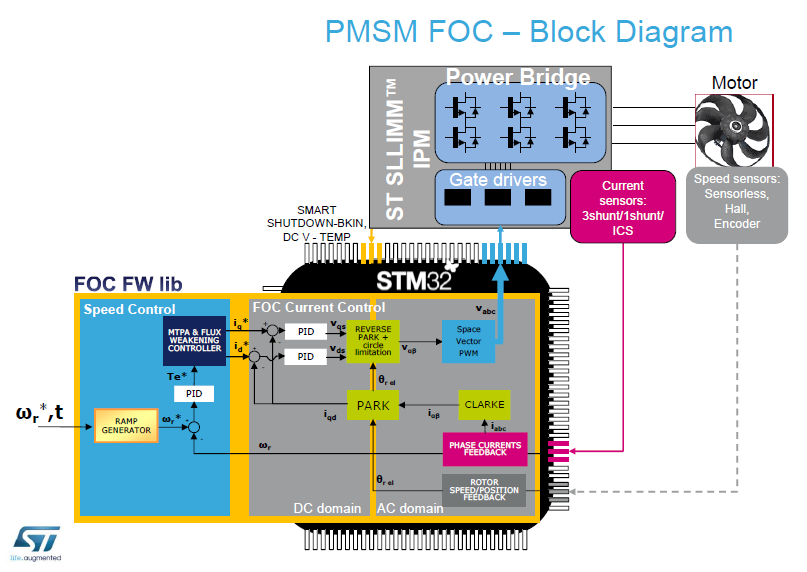
Continuation of https://github.com/bipropellant/bipropellant-hoverboard-firmware/issues/32
Concrete information can be added here: https://github.com/bipropellant/bipropellant-hoverboard-firmware/wiki/Notes-on-BLDC-Drive-and-Hoverboard-motors or as additional pages on the wiki :).