Closed rene-dev closed 9 years ago
Hi Rene
Without knowing exactly what is in the clone it's hard to say. The authentic st-link is an stm32f103 which has USB, the f101 does not have. I don't know how they would make an st-link clone without USB. The best I can suggest it to get one and try it out. No guarantee it works though.
Cheers, Gareth
On Fri, Jan 9, 2015 at 11:59 PM, Rene Hopf notifications@github.com wrote:
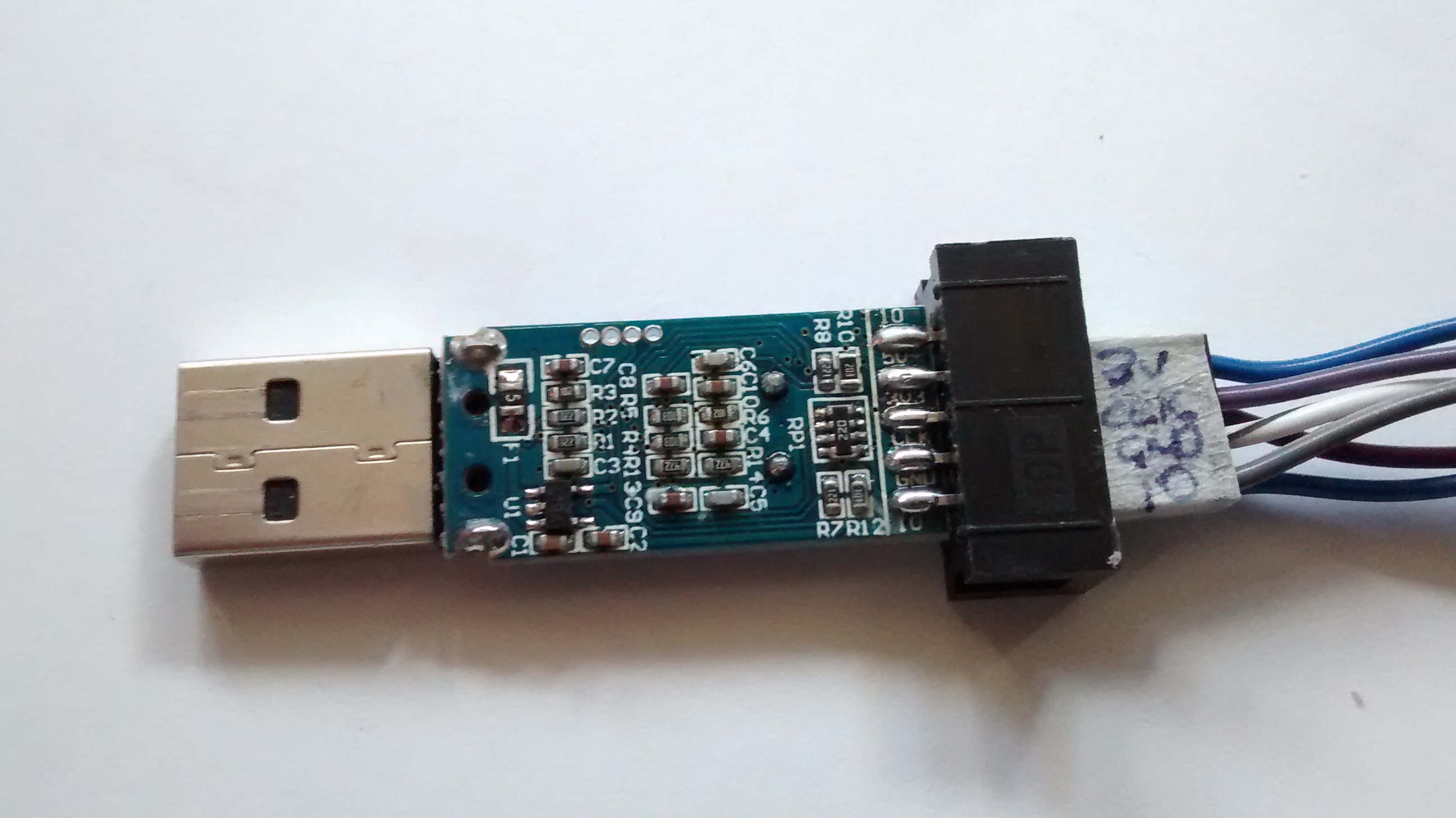
I am wondering if it works on these cheap stlink clones:
http://www.ebay.com/itm/ST-Link-V2-mini-Emulator-Downloader-Programming-Unit-Random-Color-STM8-STM32/251609973875 they have an stm32f101 inside.
Rene
Reply to this email directly or view it on GitHub https://github.com/blacksphere/blackmagic/issues/62.
Black Sphere Technologies Ltd.
Web: www.blacksphere.co.nz Mobile: +64 27 777 2182 Tel: +64 9 478 8885 Skype: gareth.mcmullin LinkedIn: http://nz.linkedin.com/in/gsmcmullin
I actually ordered two of those and they arrived today. They contain a STM32F101CBT6 (128 kB flash, not too bad), and as gsmcmullin said, have officially no USB support. I initially thought that the chinese had implemented bitbanged USB, but some google-fu turned up this http://bbs.21ic.com/icview-107887-1-1.html (chinese), that indicates that the 101 chip is (more or less) identical to the 103 and actually has USB support, though it is not tested and might be out of spec.
TL;DR It might actually be fully compatible. I'll do some more research and return when I find out anything more.
I started drawing a schematic.
I can now confirm that the stlink version of blackmagic works out of the box on this device (tested against 1b2cd547bc79c0693a0c64232211e884b1348348, i.e latest). I flashed it using openocd and another stlink through the test pads.
wow. Is it just responding on the usb, or do the swd header pins even match up and debugging works?
It seems to work all the way, I connected to another stm32f101 and it behaved as expected. I did a quick compare of your schematic against this one http://www.micromouseonline.com/wp/wp-content/uploads/2014/01/mini-st-link-v2.png and things line up :). I have no idea where the BMP's debug UART gets pinmapped, but perhaps the SWIM pin should be repurposed as UART Rx instead of serial trace input; a debug UART is easier to use than tracing imho.
Hi! Would you please help me? I have this chinese stlinkv2 but it does not work w/ openocd. It fails when I try to flash.
I have the same st-link clone (same date on pcb) and was able to flash it with modified code. I do it because last revision (https://github.com/blacksphere/blackmagic/commit/f4eda28a053abde3441e0ded49f94fecb3fdedd0) generate to big binary and also this clone does not have exactly the same hardware than original st-link V2. Pin PC 13 is unconnected (pulled low in original). This make the software not correctly identify the version. With incorrect identification, the led is off.
Hey,
first of all I am damn new to STM32 and BMP so please be forgiving if I ask obvious questions. So I managed it to flash a CH ST-Link v2 clone, like above, with the latest (gd6e2977
) BMP firmware. Works like a charm:
lenny@ubuntu14:[~/mcu/stm32/blackmagic/scripts]$ arm-none-eabi-gdb
GNU gdb (GNU Tools for ARM Embedded Processors) 7.8.0.20150604-cvs
Copyright (C) 2014 Free Software Foundation, Inc.
License GPLv3+: GNU GPL version 3 or later <http://gnu.org/licenses/gpl.html>
This is free software: you are free to change and redistribute it.
There is NO WARRANTY, to the extent permitted by law. Type "show copying"
and "show warranty" for details.
This GDB was configured as "--host=x86_64-unknown-linux-gnu --target=arm-none-eabi".
Type "show configuration" for configuration details.
For bug reporting instructions, please see:
<http://www.gnu.org/software/gdb/bugs/>.
Find the GDB manual and other documentation resources online at:
<http://www.gnu.org/software/gdb/documentation/>.
For help, type "help".
Type "apropos word" to search for commands related to "word".
(gdb) target extended-remote /dev/ttyACM1
Remote debugging using /dev/ttyACM1
(gdb) monitor swdp_scan
Target voltage: unknown
Available Targets:
No. Att Driver
1 STM32F3
(gdb) attach 1
Attaching to Remote target
0xfffffffe in ?? ()
(gdb) quit
A debugging session is active.
Inferior 1 [Remote target] will be detached.
Quit anyway? (y or n) y
Detaching from program: , Remote target
lenny@ubuntu14:[~/mcu/stm32/blackmagic/scripts]$
As you see, the prob's UARTs were mapped to /dev/ttyACM1
and /dev/ttyACM2
. Now to my problem:
lenny@ubuntu14:[~/mcu/stm32/blackmagic/scripts]$ arm-none-eabi-gdb
GNU gdb (GNU Tools for ARM Embedded Processors) 7.8.0.20150604-cvs
....
Type "apropos word" to search for commands related to "word".
(gdb) source hexprog.py -d /dev/ttyACM1 ../../maple_mini_boot20.bin
hexprog.py -d /dev/ttyACM1 ../../maple_mini_boot20.bin: No such file or directory.
(gdb)
File to flash exists and is reachable. To me it seems to relate to denis-fr's comment but I might be wrong and I'm missed something...
hexprog.py is not a gdb command. It is supposed to be used on the command line.
Hi @milkpirate. It looks like everything is working fine.
The hexprog.py
script is not intended to be run from inside GDB. It also requires an intel hex file.
To load a hex file from gdb, do:
load file.hex
To load a binary file from gdb, do:
restore ../../maple_mini_boot20.bin binary <address>
Hey,
@esden: Yes I know, but source
is.
@gsmcmullin: Ahh right. I converted the binary file to Intel HEX. Dont know why I havent tried that earlier. Then hexprog.py
runs smoothly:
Black Magic Probe -- Target Production Programming Tool -- version 1.0
Copyright (C) 2011 Black Sphere Technologies
License GPLv3+: GNU GPL version 3 or later <http://gnu.org/licenses/gpl.html>
Black Magic Probe (Firmware v1.6-rc0-257-gd6e2977) (Hardware Version 0)
Copyright (C) 2015 Black Sphere Technologies Ltd.
License GPLv3+: GNU GPL version 3 or later <http://gnu.org/licenses/gpl.html>
Target device scan:
Target voltage: unknown
Available Targets:
No. Att Driver
1 STM32F3
Attaching to target 1.
FLASH memory -- Offset: 0x8000000 BlockSize:0x800
Programming target
Flash write failed! Is device protected?
So the next step was to add an -r
which lead to:
...
Attaching to target 1.
Removing device protection.
Traceback (most recent call last):
File "blackmagic/scripts/hexprog.py", line 155, in <module>
target.run_stub(stub_opterase, 0x20000000)
File "/home/lenny/mcu/stm32/blackmagic/scripts/gdb.py", line 203, in run_stub
regs = list(self.read_regs())
File "/home/lenny/mcu/stm32/blackmagic/scripts/gdb.py", line 166, in read_regs
return struct.unpack("=20L", data)
struct.error: unpack requires a string argument of length 80
lenny@ubuntu14:[~/mcu/stm32]$
The suggested gdb
commands dont seem to work either:
(gdb) load maple_mini_boot20.hex
Loading section .sec1, size 0x1bd4 lma 0x0
Load failed
(gdb) restore maple_mini_boot20.bin binary 0x08000000
Restoring binary file maple_mini_boot20.bin into memory (0x8000000 to 0x8001bd4)
Writing to flash memory forbidden in this context
(gdb)
@themadinventor did You find where uart debug is workin? Or not working at all?
look's like pin 12/13 (PA2/PA3) are UART pins and need to be connected to additional header. Anyone could test it?
Are you sure you can use PA2 / PA3
The Stlink dongle I have, is basically like this schematic
http://www.avrki.ru/picture/articles/samodelniy_st_link_v2/shemf_st_link_v2.jpg
So PA2 and PA3 are not connected
I think to be able to use a UART on these dongles you'll need to remap UART1 onto its alternate pins of PB6 and PB7 and use the pins that are labelled as SWIM and SWIM_RST. These connections are via resistors, but I recall trying this some time ago, and normally these low value resistors didnt seem to cause a problem. As its only 22 ohms in series with PB6 PB7 is the worst as it has 680R and 22R in series.
You also need to make sure that PB5, and PB9 and PB10 are all floating, as PB7,9 and 10 are linked and PB5 and 6 are linked.
But other pins default to floating input so should be OK as long as they are not explicitly configured as either a UART or GPIO output.
PS. When I get time, I was going to revisit this, as I had some old code BMP code that runs on these, but I'd need to dig it out and see what I need to do in order to make it work with the revised code architecture.
PS.
I found basically the same circuit elsewhere as well. So I suspect most dongles are the same.
http://we.easyelectronics.ru/uploads/images/00/31/28/2013/05/11/3012f7.jpg
The only difference being the pin order on connector on the end of the dongle
Just a heads up as I wanted to look at black magic probe as an alternative to the stlink clone I have for various reasons. I built a firmware using the patches available in the forums, but the usart RX wasn't working for some types of serial adapters.
The reason for this was that on my clone, there isn't a 680R in series with 22R, its actually a 680 pullup to 3v rail. There is however an additional ~220K resistor in series after the pullup.
The reason RX wasn't working for me was that the USB USART adapter I had included a 1K inline resistor on the TX pin, which formed a nice voltage divider with the 680R pullup, resulting in a low of around 2V.
I swapped out the 680R for a 20K on the board and logic low is now working fine.
Hope this helps someone who can't work out why RX isn't working on a clone device, but TX works fine once patched.
PS - Didn't check if I could remove it or not as wasn't sure if the PB7 pin has input pullup enabled or not.
@enly1
Which STLink dongle are you using?
I have it partially working, including UART on a "Baite" branded STLink from AliExpress, but I was also interested in getting it to work on the same one as @rene-dev posted the internal photos of.
However, If the schematic posted by @rene-dev is correct (which I think it probably is), then to make the UART work would require the use of 2 UARTS
i.e Neither PB13 or PB14 is usable as a UART
However PB6 is the USART1_TX via ALT pin mapping and PB11 is USART3_RX on its primary mapping So the code would need to be modified quite a lot to configure 2 UARTS (1 and 3) and put 1 on its ALT pins
I'm not sure if the F101C8 has USART3
BTW. As previously discussed, although the STM32F101 is not supposed to have USB, in reality it does have, probably because ST are selling F103's as F101's Its also likely that it has 128k flash, because most F103C8's are only supposed to have 64k no one has ever found a F103C8 that does not have 128k.
@rogerclarkmelbourne will check tonight - but I think it was one of the v1 clones with an stm32f101 on it. Pin remapped the uart and removed one of the resistors to get it to work.
@enly1
Thanks.
I noticed that the resistors seem to stop serial loopback working, but I could send and receive to a separate USB Serial.
So I suspect the problem is the resistor values e.g. the 680 ohms in series, though I think there is also a pullup which may not be helping either
The problem I had (from memory) was a 680K pullup pulling low too high for the usb usart dongle I was using - swapping to 20k did the trick and allowed low to be low on RX.
Will dig out the details later - but mine has been working fine ever since swapping it out and using usart for debugging all the time ...
On 8 June 2017 at 10:14, Roger Clark notifications@github.com wrote:
@enly1 https://github.com/enly1
Thanks.
I noticed that the resistors seem to stop serial loopback working, but I could send and receive to a separate USB Serial.
So I suspect the problem is the resistor values e.g. the 680 ohms in series, though I think there is also a pullup which may not be helping either
— You are receiving this because you were mentioned. Reply to this email directly, view it on GitHub https://github.com/blacksphere/blackmagic/issues/62#issuecomment-307019748, or mute the thread https://github.com/notifications/unsubscribe-auth/AFif6kuFQoU59NRFQDpj6u3vlJ4mGVyhks5sB59KgaJpZM4DQTpi .
I think your STLink dongle may be different from mine.
AFIK the schematic in mine is something like this http://www.avrki.ru/picture/articles/samodelniy_st_link_v2/shemf_st_link_v2.jpg but the pinout to the plug is different
It seems to have 680 ohms in series with PB7 and another 680 ohms to 3.3V (via the PB7 to PB11 connection)
So it looks like the SWIM pin would be pulled to 3.3V/2 = 1.65 and PB7 will have to drive against that all the time.
These were the board I have - I swapped R10 for a 20K resistor to help out with the voltage divider situation. Worked with all my usb uarts and loopback tests.
PS - label on the aluminum cover shows st-link v2.
Which build target ("platform") are you using with this dongle ?
stlink or swlink (or something else)
BTW. Mine also has STLink V2 written on it, so I'm sure its the same one.
I presume you must have connected Serial TX and RX to Pins 1 and 3 (RST and SWIM) (possibly the other way around)
In which case, isn't RST connected to either PB0 or PB6, depending on whether RST means NRST or SWIM_RST and SWIM connected to PB7 ?
I presume RST must mean SWIM_RST otherwise its not going to work.
I'm now also guessing that you must be using code based on the "swlink" version, as that version uses the UART on PB6 and PB7
Re: Changing R10 for 20k. Can you post a link to the schematic, as I don't think I have one which accurately reflects the resistor numbers
Also. Why didn't you simply remove the pullup ?
It was a while ago now, but I think it was stlink target during make.
Yes, RST = SWIM_RST.
I can't quite remember, but think I added the gpio config for alt pins on USART1. Can't find the code now though to check.
On 9 June 2017 at 02:01, Roger Clark notifications@github.com wrote:
Which build target ("platform") are you using with this dongle ?
stlink or swlink (or something else)
BTW. Mine also has STLink V2 written on it, so I'm sure its the same one.
I presume you must have connected Serial TX and RX to Pins 1 and 3 (RST and SWIM) (possibly the other way around)
In which case, isn't RST connected to either PB0 or PB6, depending on whether RST means NRST or SWIM_RST and SWIM connected to PB7 ?
I presume RST must mean SWIM_RST otherwise its not going to work.
I'm now also guessing that you must be using code based on the "swlink" version, as that version uses the UART on PB6 and PB7
Re: Changing R10 for 20k. Can you post a link to the schematic, as I don't think I have one which accurately reflects the resistor numbers
Also. Why didn't you simply remove the pullup ?
— You are receiving this because you were mentioned. Reply to this email directly, view it on GitHub https://github.com/blacksphere/blackmagic/issues/62#issuecomment-307250337, or mute the thread https://github.com/notifications/unsubscribe-auth/AFif6uNsk7TdPDww8rPu-F8ZjDpvaDMMks5sCH1EgaJpZM4DQTpi .
No worries
Hi guys,
I'm jumping in the discussion as I'm interrested in remaping my stlink v2 mini RST and SWIM pins to usart. I have the exact same board as @enly1 posted.
@enly1 could you please give me a bit more details on your solution?
Regards
Its also likely that it has 128k flash, because most F103C8's are only supposed to have 64k no one has ever found a F103C8 that does not have 128k
@enly1 @rogerclarkmelbourne lucky me, I think I have one! :| Last evening, I was trying to flash BlackMagic onto a "Blue Pill" with the STM32F103C8, and pretty much comprehensively confirmed there's only 64KB
For one, dfu-util -l
has a the text /0x08000000/8*001Ka,056*001Kg
, which I assume means "8KB bootloader at 0x08000000 and 56 KB free after bootloader" (true?):
dfu-util 0.8
Copyright 2005-2009 Weston Schmidt, Harald Welte and OpenMoko Inc.
Copyright 2010-2014 Tormod Volden and Stefan Schmidt
This program is Free Software and has ABSOLUTELY NO WARRANTY
Please report bugs to dfu-util@lists.gnumonks.org
Found DFU: [1d50:6017] ver=0100, devnum=40, cfg=1, intf=0, alt=0, name="@Internal Flash /0x08000000/8*001Ka,056*001Kg", serial="76543210"
Further, when I try to flash BlackMagic, (now 58,364 bytes), I get this error:
0 $ sudo dfu-util -d 1d50:6017 -s 0x08002000 -D blackmagic.bin --verbose
dfu-util 0.8
Copyright 2005-2009 Weston Schmidt, Harald Welte and OpenMoko Inc.
Copyright 2010-2014 Tormod Volden and Stefan Schmidt
This program is Free Software and has ABSOLUTELY NO WARRANTY
Please report bugs to dfu-util@lists.gnumonks.org
dfu-util: Invalid DFU suffix signature
dfu-util: A valid DFU suffix will be required in a future dfu-util release!!!
Opening DFU capable USB device...
ID 1d50:6017
Run-time device DFU version 011a
Claiming USB DFU Interface...
Setting Alternate Setting #0 ...
Determining device status: state = dfuIDLE, status = 0
dfuIDLE, continuing
DFU mode device DFU version 011a
Device returned transfer size 1024
DfuSe interface name: "Internal Flash "
Memory segment at 0x08000000 8 x 1024 = 8192 (r)
Memory segment at 0x08002000 56 x 1024 = 57344 (rew)
Downloading to address = 0x08002000, size = 58364
dfu-util: Last page at 0x080103fb is not writeable
I am otherwise able to flash the smaller dfu_upgrade.bin
with no problems:
0 $ sudo dfu-util -d 1d50:6017 -s 0x08002000 -D dfu_upgrade.bin --verbose
dfu-util 0.8
Copyright 2005-2009 Weston Schmidt, Harald Welte and OpenMoko Inc.
Copyright 2010-2014 Tormod Volden and Stefan Schmidt
This program is Free Software and has ABSOLUTELY NO WARRANTY
Please report bugs to dfu-util@lists.gnumonks.org
dfu-util: Invalid DFU suffix signature
dfu-util: A valid DFU suffix will be required in a future dfu-util release!!!
Opening DFU capable USB device...
ID 1d50:6017
Run-time device DFU version 011a
Claiming USB DFU Interface...
Setting Alternate Setting #0 ...
Determining device status: state = dfuIDLE, status = 0
dfuIDLE, continuing
DFU mode device DFU version 011a
Device returned transfer size 1024
DfuSe interface name: "Internal Flash "
Memory segment at 0x08000000 8 x 1024 = 8192 (r)
Memory segment at 0x08002000 56 x 1024 = 57344 (rew)
Downloading to address = 0x08002000, size = 6764
Download [ ] 0% 0 bytes Poll timeout 100 ms
Poll timeout 0 ms
Download from image offset 00000000 to memory 08002000-080023ff, size 1024
Poll timeout 100 ms
Poll timeout 0 ms
Poll timeout 100 ms
Poll timeout 0 ms
Download from image offset 00000400 to memory 08002400-080027ff, size 1024
Poll timeout 100 ms
Poll timeout 0 ms
Poll timeout 100 ms
Poll timeout 0 ms
Download from image offset 00000800 to memory 08002800-08002bff, size 1024
Poll timeout 100 ms
Poll timeout 0 ms
Poll timeout 100 ms
Poll timeout 0 ms
Download from image offset 00000c00 to memory 08002c00-08002fff, size 1024
Poll timeout 100 ms
Poll timeout 0 ms
Poll timeout 100 ms
Poll timeout 0 ms
Download from image offset 00001000 to memory 08003000-080033ff, size 1024
Poll timeout 100 ms
Poll timeout 0 ms
Poll timeout 100 ms
Poll timeout 0 ms
Download from image offset 00001400 to memory 08003400-080037ff, size 1024
Poll timeout 100 ms
Poll timeout 0 ms
Poll timeout 100 ms
Poll timeout 0 ms
Download from image offset 00001800 to memory 08003800-08003a6b, size 620
Poll timeout 100 ms
Poll timeout 0 ms
File downloaded successfully
launching the STM32 Flash loader demonstrator (UM0462) indicates at startup time that it found a 64K device:
There's a comment here that:
The STM32duino core have two uploading board settings, one for 64 KB and one for 128 KB.
So perhaps there's still hope? However I've been unable to find these "settings" for memory (?)
And so ya - I also have a ST-Link that I will be trying, but the chip is so hard to read, I cannot tell if that's a "B" or an "8".
*edit: spelling
@gojimmypi
I guess you were using a version of blackmagic_dfu prior to commit b09a522:
Before this change the bootloader always reported a total of 64k flash for the stlink target regardless of the actual chip, and dfu-util refuses to flash a firmware image that is larger than the reported flash size. The newer bootloader reads the chip's flash size register at runtime and if that reports 64k it passes on 128k instead, because even the STM32F103C8 chips that really have 128k claim to only have 64k in their flash size register.
So your test was only for the reported flash size, not for the actual flash size and if your C8 really has 128k you should be able to use it if after upgrading to the latest bootloader.
description of the string, from st:
USBD_DFU_MEDIA Interface USBD_DFU_MEDIA Parameter Description: The description of the flash (used by PC tool DFuSe) Each Alternate setting string descriptor must follow this memory mapping so that the PC Host Software can decode the right mapping for the selected device: @: To detect that this is a special mapping descriptor (to avoid decoding standard descriptor) /: for separator between zones Maximum 8 digits per address starting by “0x” /: for separator between zones Maximum of 2 digits for the number of sectors : For separator between number of sectors and sector size Maximum 3 digits for sector size between 0 and 999 1 digit for the sector size multiplier. Valid entries are: B (byte), K (Kilo), M (Mega) 1 digit for the sector type as follows: – a (0x41): Readable – b (0x42): Erasable – c (0x43): Readable and Erasabled (0x44): Writeable – e (0x45): Readable and Writeable – f (0x46): Erasable and Writeable – g (0x47): Readable, Erasable and Writeable Note: If the target memory is not contiguous, the user can add the new sectors to be decoded just after a slash"/" as shown in the following example: "@Flash /0xF000/14Ka/0xE000/14Kg/0x8000/224Kg"
thank you @rma-x
Could people with a "baite"board try https://github.com/UweBonnes/blackmagic/tree/baite
If PC13/14 float and PB11 is pulled high, recognize as baite. Handle as rev.1 board. Deciphered from: http://www.avrki.ru/picture/articles/samodelniy_st_link_v2/shemf_st_link_v2.jpg
I have some Baite STLink dongles, but don't have time to test until the weekend
@UweBonnes: I've tried your baite branch and it works. First I flashed the stlink version, then merged your baite branch and flashed the new bin using the stm32.mem.py. In µC.net I reported you an error when using the python flash scripts, with the stlink version it works. The version output is:
(gdb) monitor ver Black Magic Probe (Firmware v1.6.1-114-gb9c5bb9) (Hardware Version 1)
but there is another PR for the baite platform: https://github.com/blacksphere/blackmagic/pull/274 There the UART pins are PB_6/PB_7, which is more convenient because these pins are on the 10 pin SWD connector, https://wiki.cuvoodoo.info/doku.php?id=jtag The 680R pull-up at PB11 is very strong and also connected to PB_7 (RxD), I would rather remove this R for proper operation of the UART. I've tested this on another adapter, it works better without this pullup. But then your baite-detection doesn't work, also when PB_7 is used for the UART.
My conclusion: use the PR #274 for this hardware version.
@rixnco have you been able to flash your boards? Very interested in converting my clone to BMP to use SWD/SWC + RX
@orangefour. No I ended up using a bluepill board.
This guide helped me (mac user) to install Black Magic Probe on an ST-Link V2. You will need two of those devices, one to program the other.
https://embdev.net/articles/STM_Discovery_as_Black_Magic_Probe
I found the correct pins to use for my device here: https://madnessinthedarkness.transsys.com/blog:2017:0122_black_magic_probe_bmp_on_st-link_v2_clones
@gojimmypi same here. Last page is not writeable and stuff. Looks like those "unique" 64k RAM ones (56 KB free after bootloader). What I can do about it?
dfu-util.exe -l
Found DFU: [1d50:6017] ver=0100, devnum=45, cfg=1, intf=0, path="1-3", alt=0, name="@Internal Flash /0x08000000/8*001Ka,056*001Kg", serial="C4DFCC06"
Looks like a regular $2 blue pill board, got it from ebay.
Upd: used ST-Link Demonstrator GUI via UART (force select 128K, select 8002000) and it worked. Instructions found here https://gojimmypi.blogspot.com/2017/07/BluePill-STM32F103-to-BlackMagic-Probe.html
Have a look at (blackmagic)/scripts/stm32mem. It does not care about the DFU header but tries to write above 64 kByte even on a F103C8. But it compares the result and will show if there is no success.
@UweBonnes https://github.com/UweBonnes/blackmagic/tree/baite works for me with a baite adapter.
Hey guys,
lately I have to flash an STM and I dug out my BMP (I flashed a little up the thread). Since I thought I might update it to the latest version I can across here again. But the baite branch seems removed. Was ist merged into master? Which binary should be used?
ST Platforms that reuse SWJ pins are handled by the swlink platform. Platforms that claim STLink compatibility are handled by the stlink platform. Read the Readme.md files in the platform directory.
I am wondering if it works on these cheap stlink clones: http://www.ebay.com/itm/ST-Link-V2-mini-Emulator-Downloader-Programming-Unit-Random-Color-STM8-STM32/251609973875 they have an stm32f101 inside.
Rene