camcamfresh / Xiaomi-M365-BLE-Controller-Replacement

Replacing the BLE Controller with a Cellular Controller
142 stars 34 forks source link

How to turn on controller? #10

Open NickGoumas opened 5 years ago

NickGoumas commented 5 years ago

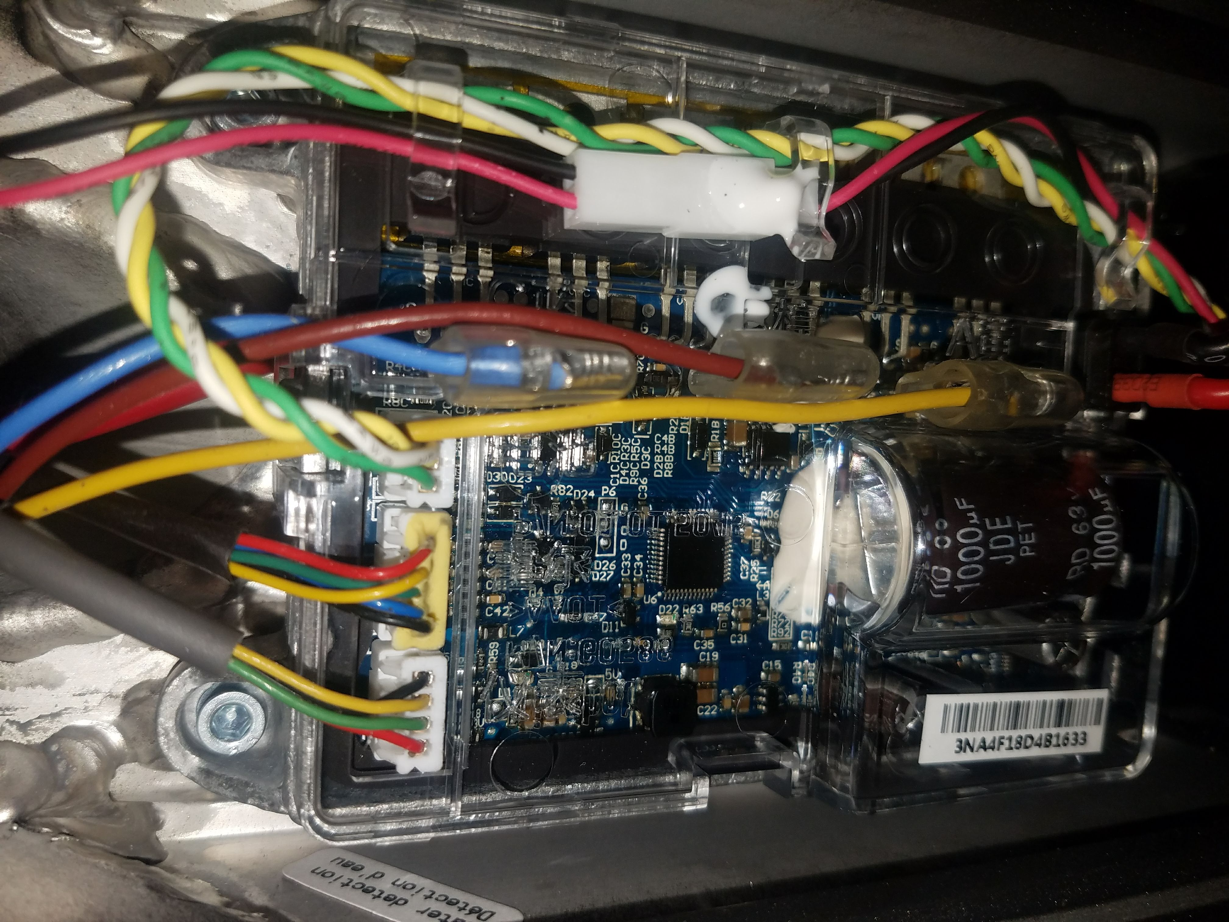
I have the BLDC motor wheel, battery pack and motor controller from an original scooter. I'm trying to simply send a signal to the controller from a microcontroller. How do I turn on the controller to get it ready to start accepting messages? On the controller board there is a 4 pin connector with labels on the PCB. From top to bottom the labels are "G - T - P - 5". "G" and "5" are ground and 5v while I believe "T" is the data line for communication to the BLE which is normally in the handlebar. "P" seems like some sort of power button but I can't seem to get the controller to stay ON. If I connect 5v to "P" momentarily the controller's red LED comes on and the green LED flashes slowly for 35 seconds, then the lights turn off. Any advice?

smartinick commented 5 years ago

connect a pushbutton between P and G. push it short to turn on, when it's on, push it short oncefor turning on/off light, twice for switching normal/eco mode and push it long for turning the scooter off.

if there's no data sent to the esc, and it will turn off itself after a short while...

jacknab commented 5 years ago

If you take a small screw driver and touch the 2nd PIN (P Pin) the scooter should turn on. The P pin is the 40V power which is the green wire. As for your controller turning off after 35 seconds when it turns off do you hear the beep sound? Also are you hearing any beep sound when you turn it on?

You mentioned you touched pins 5 and P to get the scooter turned on, touching those 2 pins together will burn out the ble controller (i know from experience) if you touched them together like a quick tap you probably didn't cause any damage to the ble controller, when I burned out my controller I noticed only 2 of the leds on the board would light up and as I kept messing with the board the longer it was powered on I noticed another LED would go out.

Because if the controller isn't connected up correctly the tail light would blink in a set pattern and the controller would beep repeatedly in a set pattern.

I would check the grey controller cable that runs down through the handle bar to the motherboard/battery area. This would mean disconnect the BLE controller and remove the battery protection cover, and unplug the grey cable from the motherboard and gently pull the cable upwards through the top to remove the entire cable, then inspect the entire cable looking for any cuts into the wiring.. If you do find a cut this could be the cause.

If you are interested in testing something (it would require you to remove the outter layer of the grey cable that runs out of the handlebar and back into the bottom V neck bar to the controller area. remove a small portion of the grey wire wrap exposing the 4 inner wires (Red, Green, Yellow, Black)

You will want to cut the Green wire, cut small portion of the green wire wrapping so your able to connect the 2 wires back together.

Touch the 2 wires together and turn on your scooter once the scooter is turned on break the connection of the green wires, so they are no longer touching.
If the scooter stays on that means the problem lays within the BLE Controller If the scooter still powers off the problem is either in the motherboard controller or battery

*cutting the green wire, cuts the 40V power from the BLE which is used to turn on/off the scooter

NickGoumas commented 5 years ago

So when I short P and G I get the same results. Red LED comes on and green LED flashes for a short time. I'm powering a Particle Photon using the 5v and G pins and and connecting the Photon's TX pin to T on the motor controller. Nothing happens.

I wonder if I'm doing something wrong or possibly the motor controller is bad?

NickGoumas commented 5 years ago

So I just saw @jacknab comment so I'll explain my setup a bit better. I don't have a full scooter, just the wheel motor, battery pack and motor controller. I don't have the BLE controller or it's wiring harness that would run up to the handlebar.

I don't see anything on the motor controller board that could beep so I'm assuming you're asking if the BLE board is beeping? (Which I don't have so not sure.)

Do I need the BLE controller or is it possible to control the wheel with just a micro? I have a particle photon board that I'm using right now. Thanks!

jacknab commented 5 years ago

ah, well i am not sure... i have the particle electron i am not sure if the 2 boards work the same.

On Mon, Nov 19, 2018, 2:17 PM Nick <notifications@github.com wrote:

So I just saw @jacknab https://github.com/jacknab comment so I'll explain my setup a bit better. I don't have a full scooter, just the wheel motor, battery pack and motor controller. I don't have the BLE controller or it's wiring harness that would run up to the handlebar.

I don't see anything on the motor controller board that could beep so I'm assuming you're asking if the BLE board is beeping? (Which I don't have so not sure.)

Do I need the BLE controller or is it possible to control the wheel with just a micro? I have a particle photon board that I'm using right now. Thanks!

— You are receiving this because you were mentioned. Reply to this email directly, view it on GitHub https://github.com/camcamfresh/Xiaomi-M365-BLE-Controller-Replacement/issues/10#issuecomment-440044587, or mute the thread https://github.com/notifications/unsubscribe-auth/ACnEbGcqXFrEQNrkaZ4SwygrRyON8GL_ks5uwx_jgaJpZM4YoTfX .

jacknab commented 5 years ago

u say u dont have full scooter... could u take a photo on ur phone and email to me so i can see your complete wiring setup from battery to motherboard to the brushless motor, to your photon.

On Mon, Nov 19, 2018, 2:09 PM Nick <notifications@github.com wrote:

So when I short P and G I get the same results. Red LED comes on and green LED flashes for a short time. I'm powering a Particle Photon using the 5v and G pins and and connecting the Photon's TX pin to T on the motor controller. Nothing happens.

I wonder if I'm doing something wrong or possibly the motor controller is bad?

— You are receiving this because you commented. Reply to this email directly, view it on GitHub https://github.com/camcamfresh/Xiaomi-M365-BLE-Controller-Replacement/issues/10#issuecomment-440042309, or mute the thread https://github.com/notifications/unsubscribe-auth/ACnEbPalHeJr-irdCmejrDmWTD7Klficks5uwx3ugaJpZM4YoTfX .

jacknab commented 5 years ago

jacknabvoip@gmail

On Mon, Nov 19, 2018, 2:09 PM Nick <notifications@github.com wrote:

So when I short P and G I get the same results. Red LED comes on and green LED flashes for a short time. I'm powering a Particle Photon using the 5v and G pins and and connecting the Photon's TX pin to T on the motor controller. Nothing happens.

I wonder if I'm doing something wrong or possibly the motor controller is bad?

— You are receiving this because you commented. Reply to this email directly, view it on GitHub https://github.com/camcamfresh/Xiaomi-M365-BLE-Controller-Replacement/issues/10#issuecomment-440042309, or mute the thread https://github.com/notifications/unsubscribe-auth/ACnEbPalHeJr-irdCmejrDmWTD7Klficks5uwx3ugaJpZM4YoTfX .

NickGoumas commented 5 years ago

wiring_setup

So in this picture the battery and wheel are connected as they would be in the scooter. The four pin connector that usually goes up to the handlebar is used to power the particle board. Pins are "G - T - P - 5" with G and 5 connected to ground and Vin on the particle. The white wire on the particle is simply feeding 3.3v to the analog input used to read speed, A4. This is just to have a constant speed output to test with. The yellow wire is connected to TX of the particle and I've been trying to touch this wire to the T pin on the motor controller without success.

EDIT: Ignore the arduino, I'm just using it's breadboard.

jacknab commented 5 years ago

I took a photo of the wiring in 1 of my scooters. Just for a reference.

In your code your writing to the photon, do have it set to use serial communication to the A4 pin? 20181119_203931

NickGoumas commented 5 years ago

I'm using the BasicMotorControl in this repo. As I understand it should be reading the throttle value from pin A4 and transmitting the hex string via the Photon's TX pin. Since I'm sending 3.3v to pin A4 it should be reading 3.3/5 = .66 so 66% throttle.

jacknab commented 5 years ago

So the connections go - ground (black) -- Yellow (TX) -- Green (40V pwr) -- Red (5V pwr)

looking at your image you have a black wire coming out of the controller that then connects into a green wire to your photon. I can not tell if that wire is connected into the ground or TX pin on the controller in your photo.

Also another thing to note.. the controller board needs to power where you see the red led light on, before your photon can connect with it via serial

Now like i mentioned I have the Particle Electron, I have been messing around with this code on 1 of my scooters, I believe I had it all set up correctly once - because from the particle cloud page when I requested the variables data it shown me DriveStatus set to 2 (which before was always showing 0) and the LightsOn set to 100 (which before was always showing 0) I attempted to push the scooter just out into the hall way of my apartment building to test if the throttle was working.. but I didn't make it even close to the door before the breadboard fell to the floor disconnecting all the wiring. I haven't got in the mood to redo all the wiring shit again.

I do not have a gps module connected to my Particle Electron but was able to still get camcamfresh's firmware.ino to flash the Electron. Have you attempted to use his firmware file on your photon?

NickGoumas commented 5 years ago

The black wire coming out of the controller connects to a green wire and then connects to ground on the Photon.

I haven't tried the full firmware.ino because I was only interested in running the motor but I'll give that a shot right now. Hopefully that does it.

NickGoumas commented 5 years ago

Still no luck using "firmware.ino".

What do you mean by "the controller board needs to power where you see the red led light on, before your photon can connect with it via serial"

When I turn on the controller the red light turns on, the green light flashes slowly for 35 seconds, then they both turn off. Does your controller do the same?

jacknab commented 5 years ago

when reading one of your comments about the controller would show a red led and then green led for couple of seconds. Got me thinking, I have only ever seen that green light come on when I am working with the Particle Electron.. So I wanted to double check - when I turn on my scooter and turn throttle the motor begins spinning. But the green light never comes on not once at any point from turning the pwer on to using the throttle. I wonder what the green light is actually connected to.

I took a small video on my phone - but had my phone make the video into animated gif to reduce file size for quicker uploading. 20181119_211754_3_2

jacknab commented 5 years ago

also if you have troubles compiling and flashing the firmware to your photon, here is a compiled file that I created.

jacknab commented 5 years ago

firmware.zip

jacknab commented 5 years ago

mine doesnt turn off no.. when I connect the Particle Electron up, the red and green light continues to blink, but it never turns off.

jacknab commented 5 years ago

after I eat something I will go mess around with that scooter and rewire up the Electron Particle to show you...

NickGoumas commented 5 years ago

Yeah I think the firmware is flashing fine. I'm using particle's web IDE and it checks and uploads without many errors. The firmware.ino had a couple errors because I didn't have the GPS library but I commented the GPS function out and it seemed fine. After flashing I would at least get the "ScooterOff" message from the particle dashboard.

jacknab commented 5 years ago

do you have a way to see the variables and write to the CloudCommand function?

If so type "poweron" or "reset" and see what happens.

jacknab commented 5 years ago

by just commenting out the GPS library you still should of got some errors, as the code calls some of the GPS library functions. without the library you should get several errors about the library functions not being defined.

jacknab commented 5 years ago

but if it flashed and your seeing scooter off message then the code must of flashed just fine like you mentioned.

NickGoumas commented 5 years ago

I commented out the library, the "gpsProcess()" function and where it's called in the main loop.

I'm going to try the "poweron" CloudCommand real quick.

jacknab commented 5 years ago

and I actually did have the problem your having when I first started messing with this code.. I then seen camcamfresh updated his readme file which mentioned the 2N2222A transistor. So I ordered a bag off ebay for something like 1.89 --- however that is what I seem to run into issue with when wiring up everything, his documents don't really show any images of how he's wiring up the transistor.

But after I got the transistors and with several attempts at getting the transistor wired correctly - I seemed to figured it out and the scooter would turn on as soon as the Electron turned on, and the green lights would continue to blink.. and the scooter never shut off.

NickGoumas commented 5 years ago

Oh I originally thought he was just using the transistor to control the headlight. It looks like he's using digital pin 0 to control a transistor to short the 40v pin and ground, and this is keeping the motor controller on.

jacknab commented 5 years ago

correct.

jacknab commented 5 years ago

I am wiring up my electron right now.. I need to dig out another transistor.. and fiddle around with connecting that up, because I can't remember how I had it wired last time that seemed to been working.

jacknab commented 5 years ago

I live in Denver, Colorado USA - there are thousands of these scooters through out the city.. almost every block corner has at least 2 parked. There are several companys that own them - as they offer scooter rental for 0.15 cents a min.

I am a charger for Bird - were I get paid to go pick up scooters that need to be charged. I first started out as a mechanic for them but there was 0 money in that.. so switched to be a charger.. but when I was a mechanic I had access to there storage nest. which was just a small office space in a small office building close to downtown, the app would send a code to the office door which unlocked it, when I was a mechanic there was a section of the office were we dropped off damaged scooter that would be pushed into a truck and taken to the city dump.. after I learned this I took a few scooters that were in pretty good shape and build me 4 good working scooters. FREE ;)

NickGoumas commented 5 years ago

That's awesome. I'm out on the east coast myself.

jacknab commented 5 years ago

Bird is moving slowly out there.. I think they are only in Richmond VA and Raleigh NC so far.

jacknab commented 5 years ago

here is a diagram he has drawn, when I asked him if he could take a picture of how he was wiring up the transistor. In his drawing he shows something that uses Pins A1 and A0 he hasnt responded yet to what those pins are used for.

https://drive.google.com/file/d/1jjfAUqVoqd4QdQPzS_AQ4LxbmgaDKu9f/view

NickGoumas commented 5 years ago

In the code it's A3 and A4, maybe he just mislabeled them in his drawing? I would guess they're the potentiometers that supply a voltage range to the brake and throttle. 0-5v range representing 0-100% brake or throttle.

jacknab commented 5 years ago

hey what happens when you connect the USB cable to the photon.. does the controller still power off?

camcamfresh commented 5 years ago

So I have been talking with Particle about getting a new Electron. In the meantime I’ve been working with a Photon on the scooter and the Serial1 port is not working properly. I had to disconnect the Photons onboard led light to get to Serial2, and then it started working. I’m talking with some people on the particle forums to see if It is a software issue. For the picture, A0 and A1 just replace the A3 and A4 on firmware.ino A few tips also: when the scooter is powered on it will show the red light on the motor controller. If the scooter doesn’t receive any serial communication the green light and the brake light will flash about every second. If the scooter receives serial data but doesn’t connect to the brake or throttle it will flash three times on the green light and brake. If the 40V power is constantly shorted with ground, then the scooter will not blink at all. Instead only the red power light will stay on and resets every few seconds.

jacknab commented 5 years ago

I actually read on there site in 1 of there documentations that you had to disconnect the led light...

jacknab commented 5 years ago

I am trying to figure out how to get the electron to do a force handshake, I been having troubles connecting to the cell towers, in the particle console says session is outdated. It seems like when I reset or disconnect the battery and reconnect it - it would refresh the handshake etc.

it says the last time my electron connected with the towers Last Handshake: Nov 18th 2018, 4:56 am

NickGoumas commented 5 years ago

Can anyone verify they've been able to run the motor of the scooter using only a separate micro (particle, arduino etc) without the handlebar board involved at all? I'm wondering if that board is doing something that's being missed here. Unlocking or activating the motor controller somehow.

smartinick commented 5 years ago

Can anyone verify they've been able to run the motor of the scooter using only a separate micro (particle, arduino etc) without the handlebar board involved at all? I'm wondering if that board is doing something that's being missed here. Unlocking or activating the motor controller somehow.

i can confirm - esp32

DoidoYo commented 5 years ago

I’ve used both esp32 and Arduino to run the motor

On Dec 5, 2018, at 10:24 AM, smartinick notifications@github.com wrote:

Can anyone verify they've been able to run the motor of the scooter using only a separate micro (particle, arduino etc) without the handlebar board involved at all? I'm wondering if that board is doing something that's being missed here. Unlocking or activating the motor controller somehow.

i can confirm - esp32

— You are receiving this because you are subscribed to this thread. Reply to this email directly, view it on GitHub https://github.com/camcamfresh/Xiaomi-M365-BLE-Controller-Replacement/issues/10#issuecomment-444523800, or mute the thread https://github.com/notifications/unsubscribe-auth/AMHiR_sLAwhsF0PtcWGMkb_AxoyKJ5vrks5u1-UYgaJpZM4YoTfX.

NickGoumas commented 5 years ago

@DoidoYo which arduino are you using? I'd much rather use an arduino but I didn't think they supported half duplex out of the box.

smartinick commented 5 years ago

half duplex or not is no problem, if no halfduplex either use softserial on a single pin, or the external resistor/diode "trick".

it's more the problem about sending packets within the correct timing and correct values - e.g. my scooter does not accept the min-throttle values used in this project, if i raise that value by 2, it works.

and then it depends what else you want to do with your micro, e.g. a single-core micro that has no dma-functions will have problems doing long-time-consuming i2c display updates while maintining the correct timing for the uart/esc packets.

so if it's "only" to replace the ble-module, no wifi/ble connectivity, no display needed.... some atmega-based arduino will make no problems at all...

BPitts2 commented 5 years ago

I'm also having issues with just getting an my Arduino Uno to do motor control. I have been playing with the basic motor control code segment.

Here's what I've been trying to do: I briefly bridge 40v (green wire) to ground (black wire). This causes the scooter to appear to turn on. Red LED on the motor controller turns on, green led flashes once every 2 seconds. Tail light also flashes at the same time as green led. While the scooter appears to be "on", I am writing the unlock request to the single wire serial. After writing the unlock, the motor and motorl are written to the serial.

However, the motor controller eventually shuts off and both the red led and green (flashing) led stop. The tail light also stops. It appears the motor controller didn't receive something it wanted to stay awake.

As mentioned above, I found that the map was not correct for my scooter either, so I obtained the minimums and maximums of my throttle and brake levers and corrected the map min/max ints. This hasn't helped yet, but I know it was needed because the analog read values wouldn't have been valid in the map anyway. So that's probably a step further than I need to be right now.

What I'm trying to understand is after the motor controller is "on", what is the next command or sequence that needs to happen to keep it awake and ready to receive motor controls?

FYI - My pin 1 TX is connected to the yellow wire (which I understand to be the data signal cable) I have not been as worried about the half-duplex serial because I didn't see anything in the basic motor control that required me to listen to the serial bus. Thus, I have NOT implemented anything other than the basic arduino serial.

BPitts2 commented 5 years ago

Scratch that - I was able to get it up and going on an Arduino Uno! Still working out some kinks, but yes, this works. My issue was a bad ground.

NickGoumas commented 5 years ago

@BPitts2 that's great news. Did you change the code at all? Using the TX pin or a digital pin with software serial? What are you using for you map values?

I have an Uno at hand and I'm really interested in seeing if I can copy your results. Thanks.

BPitts2 commented 5 years ago

Yes - I had to make a few modifications to the code. I have implemented lock and unlock, as well as tail on and tail off.

I really need to draw up a schematic so that it's easier to understand where everything goes. Basically, I am continuing to use the basic Arduino serial RX port. Either I will have to implement soft serial, or use a hardware trick with a diode if I want to READ any data from the scooter. This is a "next step" for me.

I have adjusted my map values, but this is something that still needs a little work. I don't think I'm getting full throttle. Overall, the throttle is a little wonky. It works, but I feel like something isn't all the way there.

I will probably fork this and upload what I've done for the Arduino Uno. I have a couple more interesting ideas that I want to play with. One of them is unlocking the scooter using my RFID fob.

camcamfresh commented 5 years ago

I got a replacement Electron from Particle, and now I can begin working with the scooter again. I'm probably going to add more info to the README file later in the week and I'll try to include pictures of how I have my Electron connected.

Oh I originally thought he was just using the transistor to control the headlight. It looks like he's using digital pin 0 to control a transistor to short the 40v pin and ground, and this is keeping the motor controller on.

I use two transistors in my set up. One to short the 40V pin and ground when activated, the other connects the headlight's buck converter to the 5V power line when activated (turning the headlight on). I have adjusted my map values, but this is something that still needs a little work. I don't think I'm getting full throttle. Overall, the throttle is a little wonky. It works, but I feel like something isn't all the way there.

I had a problem with the throttle in the past. The motor would be off when the throttle wasn't pressed, and the motor would go to full speed if the throttle was pressed in any way. I'm not exactly sure where the error was, but rewrote the program and believe I have fixed the issue. I need to polish the code up before posting it (I'll try to do that this week after my finals).

smartinick commented 5 years ago

I use two transistors in my set up. One to short the 40V pin and ground when activated, the other connects the headlight's buck converter to the 5V power line when activated (turning the headlight on).

which buck converter do you use? need a working type for my pcb to make :D

camcamfresh commented 5 years ago

I use the Icstation MT3608. It is a variable boost converter that I got off amazon.

smartinick commented 5 years ago

I use the Icstation MT3608. It is a variable boost converter that I got off amazon.

thanks for the info! and it works with that? i thought there should be some constant current regulation as well?

vickyfikria commented 5 years ago

Hello everyone, I have same problem with Electron-as replacement- setup. I already follow @smartinick diode trick, but still couldn't got any reply from motor controller. With diode trick, we comment this line , Serial1.halfduplex(true); // right ? or should I use Serial1.halfduplex(false); I have question Mr @camcamfresh , My Electron firmware is v.0.7.0, is this the correct version ? Thanks before