cb-geo / mpm

CB-Geo High-Performance Material Point Method
https://www.cb-geo.com/research/mpm
Other
235 stars 82 forks source link

Material Thickness for Kelvin-Voigt Boundary #708

Closed cgeudeker closed 2 years ago

cgeudeker commented 3 years ago

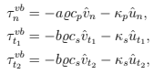
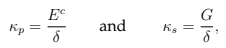
Describe the feature Kelvin-Voigt boundary equation requires adjacent material thickness in order to calculate the spring coefficient corresponding to the spring component of the boundary.

Describe alternatives

  1. The original idea was to utilize cell length in order to calculate this value. For each node where the boundary condition is applied the cell length of each cell above the node that had the same material property would be summed to derive the thickness.

    a. The problem I'm having with this approach is finding a way to determine which nodes, and therefor materials, are a part of which cells.

  2. It could also be possible to calculate by iterating through the nodes from each boundary node to find the furthest distance. The iteration would start from a boundary mode and only find the furthest distance to the node with the same material id and x coordinate, or y depending on where its being applied.

    a. The main problem with this approach is that it may just be unnecessary if the above approach is possible. b. I'm also unsure if it is possible to iterate through all the nodes within node.tcc.

Any suggestions for the above approaches or perhaps alternative approaches would be much appreciated.

Additional context Kelvin Voigt boundary equations and relating equations for calculating the spring coefficient, where material thickness is represented by delta. KV_boundary_eqs spring_coeffs

jgiven100 commented 3 years ago

@cgeudeker can you use nodal entity sets to predefine the nodes involved where this boundary condition occurs?

Also, I'm a bit confused by what exactly "material thickness" means above. I was thinking we're in a 2D plane strain problem, so cell "thickness" reminds me of the distance into/out of the page. It seems we actually need to consider the cell length or cell height (depending on the boundary orientation)?

Therefore, for a boundary condition along the model's bottom, for each node we want 1/2 the cell length for the left and right adjacent cell? Similar to a tributary area for a frame problem.

Please let me know if I'm not thinking about this correctly.

cgeudeker commented 3 years ago

Also, I'm a bit confused by what exactly "material thickness" means above. I was thinking we're in a 2D plane strain problem, so cell "thickness" reminds me of the distance into/out of the page.

I suppose when I was thinking about it the other week, I thought "thickness" was in reference to the distance from the material's edge to the point furthest away. So if we had a soil deposit, thickness would refer to the height of the lowest layer if we're looking to apply the boundary at the model's bottom. That being said, I think your interpretation may be correct when looking back at the reference thesis. What are your thoughts on this @kks32? That being said, what would we do for a "thickness" value in the case of a 3D problem? I'm not sure if there is a plan to use this feature for the 3D case, so if not then its a moot point.

jgiven100 commented 3 years ago

@cgeudeker Ignore my thoughts above - they're not right.

Looking close at the paper, \delta is a user-defined value that acts as a tuning parameter for how much the boundary acts like a dashpot.

There are some limitations based on h_min, a, and b, which should be checked. But otherwise, you get to pick it. Figure 4.16 shows how the displcament changes as \delta changes:

image

kks32 commented 3 years ago

@jgiven100 could you share the paper reference please?

jgiven100 commented 3 years ago

here is the download link

https://elib.uni-stuttgart.de/bitstream/11682/513/1/Thesis_Issam_FinalPrint.pdf

kks32 commented 3 years ago

Thanks @jgiven100 !

image

It is arbitrary, we could use like @jgiven100 suggested nodal entity set and add a special boundary condition with that thickness.

cgeudeker commented 3 years ago

Alright, so in terms of the input as a nodal entity set for an absorbing_constraint, that would look something like this:

"absorbing_constraint": [
    {
        "nset_id" : 0,
        "dir": 0,
        "thickness": 0.5
    }
]

There are some limitations based on h_min, a, and b, which should be checked.

a and b: Should we add these variables as inputs for the boundary constraint? They're "chosen depending on the wave incidence angle so that they provide maximum absorption." The thesis only used a=b=1 for its examples, so that's something to note if we make a benchmark problem based on one of these examples.

h_min: The reference thesis states "h_min is the characteristic length of the finite element mesh". I am slightly confused about where I would be looking for this value/how it may be calculated.

jgiven100 commented 3 years ago

We can add something within the boundary_conditions portion of the input.json like this

"boundary_conditions": {
...
   "absorbing_boundary": [
              {
                  "nset_id" : #,
                  "delta": #,
                  "a": #,
                  "b": #,
                  "dir": #
              }
          ],
...
},

Maybe for the above input, a and b are optional; if no values are provided in the input file, then a=b=1 will be initialized.

There are a couple different ways to define characteristic length, but if we're only concerned about a uniform square background mesh, then h_min will just be the edge length (height or length) of any cell.

cgeudeker commented 3 years ago

We can add something within the boundary_conditions portion of the input.json like this

Since this will be under the boundary_conditions portion, will I need to add corresponding files to the loads_bcs folder as well?

kks32 commented 3 years ago

@cgeudeker yes, it should be in loads_bcs