 cefn
commented
7 years ago
cefn
commented
7 years ago For reference, I propose using D8/GPIO15 connected to OFF on the Polulu.
In the new wiring, D2 is used for one of the SPI wires to the screen, so that won't fly. The only free pins currently are D0/GPIO16 D3/GPIO0 and D8/GPIO15. GPIO16 and GPIO0 might both struggle with Polulu OFF role - GPIO0 has to be pulled up on boot to ensure entry into FLASH (NormalRunning) mode. I guess the circuitry in place for this would therefore send a high pulse to OFF the moment it powers up. GPIO16 has some behaviours about sending pulses as the Cockle moves out of deep sleep too, so best avoided for removal of doubt even though it's unlikely to be a problem. That leaves D8/GPIO15 which I'll try to prove tomorrow by integrating with the final image.
References for my reasoning
You can see some of the special behaviours of Cockle pins according to their GPIO numbers here. It reports that the voltage of D8/GPIO15 helps to determine the boot mode, requiring it to be pulled down in both modes we actually use - Upload and NormalRunning, so that's what I'll try.
And this thread offers some confirmation...
Since GPIO15 (D8) is used by the boot mode process, most of the boards have this pin pulled down by an external resistor, which is stronger than internal weak pullup.
Finally the NodeMCUv2 schematic indicates D8/GPIO15 has the correct pull in place already hard-wired. After boot, we can set D8 it as a GPIO pin with an active low voltage, then pulse it active high to trigger power-off at our leisure.
Your Circuit question
For reference, there are two entirely different circuits here and your comment seems to suggest they are coupled somehow.
- One is a circuit wired across a pair of pins used to control POWER-ON behaviour. A button is normally expected to be wired across these pins, and a reed switch is equivalent to a button. In this sub-circuit there needs to be no wiring to the Cockle, and no wiring of a pull resistor.
- Entirely separately, there is a wire from a digital pin (D8 proposed) to the POWER-OFF pin of the Polulu board which should be set in software to trigger POWER-OFF when needed.
The documentation for the Polulu switch describes operation as...
OFF A high pulse (> 1 V) on this pin turns off the switch (e.g. allowing the target device to shut off its own power).
In case the pin attached to OFF was ever floating (e.g. during power up before it is told to be an output and set to a specific voltage) I originally had some concerns that it might trigger POWER-OFF just from random variations. Having selected D8, there is a resistor pull-down even when the microcontroller hasn't actively set the voltage, so fingers crossed this case should be handled automatically.
 cheapjack
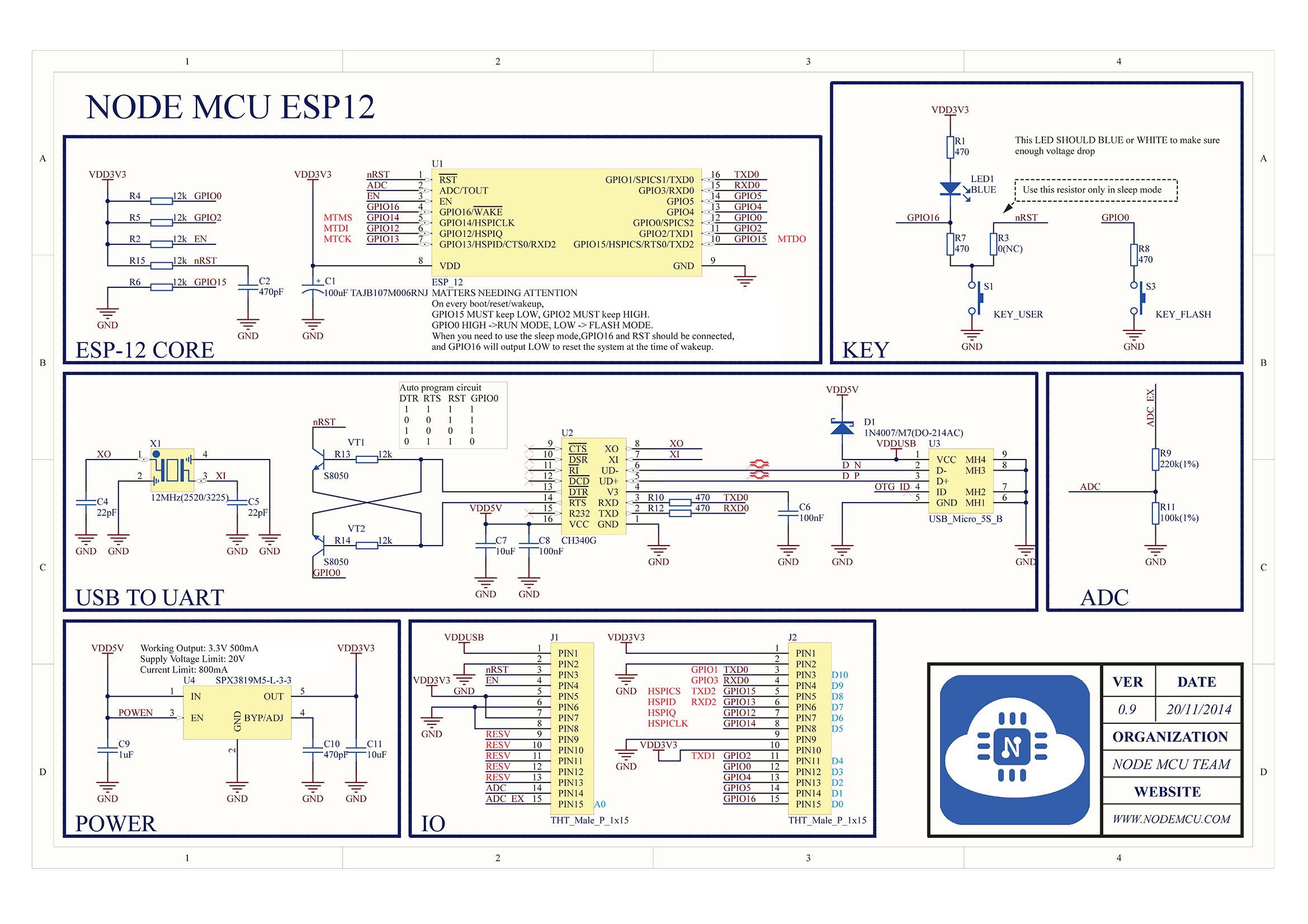
Currently using
D2connected toOFFon the Pololu in the outdoor boxes so just need to go over the code for that. Should be included universally I guess but with indoor boxes ignoring it.Bit mixed up over the resistor on the Pololu
OFFto bepull-uporpull-downCurrently its configured with 10K toPull-Downas that seemed to make sense as when the reed swtich is open (in proximity to magnet ie lid closed) it will be a 'normally low' signal ie no power and then when magnet is removed ie the lid opens, it will allow power to the Pololu which will signal high and the resistor pulls it back down cleanly afterwards...Not sure if Ive mixed this up in my basic understanding of
pull-upandpull-down