cheapjack / MileCastles

RFID driven distributed text adventure
1 stars 1 forks source link

Make a reference wiring diagram #67

Closed cheapjack closed 7 years ago

cheapjack commented 7 years ago

@cefn ive got completely lost in my wiring photograph reference Im going to need a solid reference diagram!

cheapjack commented 7 years ago

Ah can I just use this in the st7920 repo?

EXAMPLE WIRING (MCU runs at 3.3V, so use VIN to get 5V)
        * RW    - GPIO13 (Cockle pin7)  - SPI MOSI  
        * E     - GPIO14 (Cockle pin5)  - SPI Clock
        * PSB   - GND                   - Activate SPI
        * RST   - 5V                    - resetDisplay
        * V0    - 5V                    - LCD contrast
        * BLA   - 5V                    - Backlight Anode
        * BLK   - GND                   - Backlight Cathode
        * VCC   - 5V                    - USB power VIN (not 3V3)
        * GND   - 0V

    By default, attempts to wire to Hardware SPI as described at https://docs.micropython.org/en/latest/esp8266/esp8266/quickref.html#hardware-spi-bus
cheapjack commented 7 years ago

@cefn managed to wire up everything with no pot for contrast following this and what we'd previously done for the reader but unsure what to do with RS on the screen which I think is a chip select thing so do we ignore it/not connect or power it on 5V?

Should we include the pot just in case they need adjusting? Theres a handy 3mm hole we could fix a screwhead pot like the one @cefn had on his reference circuit then a small cross-head screwdriver could adjust so the public wouldnt try to...

cefn commented 7 years ago

My RS is wired direct to 5V, but unsure if the Chip Select/Slave Select thing has been figured out for sure on screens. Haven't done a lot of RFID+Screen shenanigans to prove all is sane switching between them. Possibly screen select isn't currently in use as in my circuit RS is wired direct to 5V. Been using https://github.com/olikraus/u8g2/wiki/setup_tutorial for hardware wiring reference information.

cefn commented 7 years ago

As for Potentiometer, there is a scenario in which the deployment temperature is different from the testing temperature which might require variation in the contrast setting. If it doesn't require deployment of a circuit board, then could include it, so long as it doesn't create extra potential for failure compared to direct wiring.

cefn commented 7 years ago

Seemed this issue of needing reference wiring was resolved by your experiments, but want to be sure. Did you successfully write data to the screen, then? However, I feel a reference diagram is worth doing anyway in the long run.

I have allocated D8 (as per cockle naming - actually ESP GPIO pin 15) for wiring of the Screen RS pin (seems to be active high). Means R/W and RS are neighbours on the cockle, for allocating future insulators.

That should address any issue from crosstalk between the SPI of screen vs. reader in the long run, though weirdly it wasn't an issue in integration testing, despite RS apparently being active the whole time. Whatever is sent to the card must be ignored by the screen for some reason, but I guess we can't rely on this, so using Chip Select makes sense. I think it is now in use in my testing rig.

I'm guessing we'll only know if your wiring is solid after you can run the integration test main.py.

Currently my integration test (for integration-testing hardware) is at https://github.com/cefn/avatap/blob/master/python/integration_main.py

The cockle filesystem currently looks as follows to service the integration test...

$ ampy --port /dev/ttyUSB0 ls
bitfont.py
st7920.py
mfrc522.py
faces
main.py

$ ampy --port /dev/ttyUSB0 ls faces
font_5x7.py

You can populate the dependencies like...

$ ampy --port /dev/ttyUSB0 put micropython-st7920/st7920.py
$ ampy --port /dev/ttyUSB0 put micropython-mfrc522/mfrc522.py
$ ampy --port /dev/ttyUSB0 put bitfont/bitfont.py
$ ampy --port /dev/ttyUSB0 mkdir faces
$ ampy --port /dev/ttyUSB0 put bitfont/faces/font_5x7.py faces/font_5x7.py
$ ampy --port /dev/ttyUSB0 put avatap/python/integration_main.py main.py
cheapjack commented 7 years ago
Screen
Left to Right when screen flipped and in install position with gamebox upright
        * BLK   - GND                   - Backlight Cathode
        * BLA   - 5V                    - Backlight Anode
        * RST   - 5V                    - resetDisplay
        * PSB   - GND                   - Activate SPI
        * E     - GPIO14 (Cockle pin D5)  - SPI Clock
        * RW    - GPIO13 (Cockle pin D7)  - SPI MOSI  
        * RS    - GPIO15 (Cockle pin D8)  - Chip select ?
        * V0    - 5V                    - LCD contrast
        * VCC   - 5V                    - USB power VIN (not 3V3)
        * GND   - 0V                   - Ground
RFID Reader
        * SDA        Cockle Pin D5 GPIO14 (shared with SPI Screen)
        * SCK        Cockle Pin D3  GPIO0
        * MOSI      Cockle Pin D4  GPIO2
        * MISO      Cockle Pin D2 GPIO4
        * GND      Ground
        * RST       Cockle Pin D1 GPIO5
        * 3V3        3V3

@cefn Just tried all that with wiring as above not much happening: I removed the boot.py that was there was that wrong? Screen on but no read...just tried to make filesystem the same as yours

cheapjack commented 7 years ago

actually im getting this over serial when i read a tag

Address send allocated: -64
Data send allocated: -32

which means rfid or something working?

cheapjack commented 7 years ago

oh looks like writing to the screen actually...

cheapjack commented 7 years ago

ive added an issue with more detail in an avatap issue

cheapjack commented 7 years ago

Leaving this open until we have a nice KiCad diagram I've made more detail and some reference images so far in AssemblyWiring.md

Final Wiring spec

## Screen
Left to Right when screen flipped and in install position with gamebox upright
        * BLK   - GND                   - Backlight Cathode
        * BLA   - 5V                    - Backlight Anode
        * RST   - 5V                    - resetDisplay
        * PSB   - GND                   - Activate SPI
        * E     - GPIO14 (Cockle pin D5)  - SPI Clock
        * RW    - GPIO13 (Cockle pin D7)  - SPI MOSI  
        * RS    - GPIO15 (Cockle pin D8)  - Chip select ?
        * V0    - 5V                    - LCD contrast
        * VCC   - 5V                    - USB power VIN (not 3V3)
        * GND   - 0V                   - Ground
### RFID Reader
        * SDA        Cockle Pin D5 GPIO14 (shared with SPI Screen)
        * SCK        Cockle Pin D3  GPIO0
        * MOSI      Cockle Pin D4  GPIO2
        * MISO      Cockle Pin D2 GPIO4
        * GND      Ground
        * RST       Cockle Pin D1 GPIO5
        * 3V3        3V3
cheapjack commented 7 years ago

Latest to include Pololu

Screen
Left to Right when screen flipped and in install position with gamebox upright
        * BLK   - GND                   - Backlight Cathode
        * BLA   - 5V                    - Backlight Anode
        * RST   - 5V                    - resetDisplay
        * PSB   - GND                   - Activate SPI
        * E     - GPIO14 (Cockle pin D5)  - SPI Clock
        * RW    - GPIO13 (Cockle pin D7)  - SPI MOSI  
        * RS    - GPIO15 (Cockle pin D8)  - Chip select ?
        * V0    - 5V                    - LCD contrast
        * VCC   - 5V                    - USB power VIN (not 3V3)
        * GND   - 0V                   - Ground
RFID Reader
        * SDA        Cockle Pin D5 GPIO14 (shared with SPI Screen)
        * SCK        Cockle Pin D3  GPIO0
        * MOSI      Cockle Pin D4  GPIO2
        * MISO      Cockle Pin D2 GPIO4
        * GND      Ground
        * RST       Cockle Pin D1 GPIO5
        * 3V3        3V3

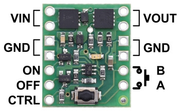
![pololu](https://a.pololu-files.com/picture/0J6761.350.jpg?a49cd139840f29608e58b4b0a77dd58f)

Soft latch, hacked USB-A to USB-B 9 (micro) male crimped all male, 2 female crimped DATA1 & DATA2 on USB-B (micro)
        * GND IN  GND from Male USB-A
        * VIN   VIN from Male USB-A
        * OFF   Cockle Pin D6
        * 10K across OFF & GND IN
        * GNDOUT   GND to Male USB-B (micro)
        * VOUT  VOUT to Male USB-B (micro)
        * DATA1   DATA1  over male female crimp
        * DATA2   DATA2  over male female crimp
cefn commented 7 years ago

Worth listing DATA2?

Also did you move the 10k or did you find that it worked in series in the place of a wire (this is certainly feasible. Previously it was wired as a pull-down between OFF and GND - or should have been). Sadly I didn't take a pic of the working configuration for reference.

cheapjack commented 7 years ago

Been working with this now until further notice more details in #86

Loom to Cockle wiring details

Screen Loom 1

BLK -> 0V [Brown] - Backlight Cathode BLA -> 5V [Red] - Backlight Anode VOUT -> UNCONNECTED [Black] - Reference voltage RST -> 5V [White] - Screen Reset NC -> UNCONNECTED [Grey] - Not Connected (unused pin) PSB -> 0V [Purple] - Parallel Serial Bus selector (indicating we are using Serial - SPI)

Screen Loom 2

E-> D5/GPIO14 [Blue] - SPI SCK (Serial Clock) R/W -> D7/GPIO13 [Green] - SPI MOSI RS -> D8/GPIO15 [Yellow] - Screen SPI Slave Select V0 -> 5V [Orange] - LCD Contrast voltage VCC -> 5V [Red] - Power supply +5V positive GND -> GND [Brown] - Power supply common negative

Reader Loom

SDA -> D4/GPIO2 (Black) - Reader SPI Slave Select SCK -> D5/GPIO14 (White) - SPI Serial Clock MOSI -> D7/GPIO13 (Grey) - SPI MOSI MISO -> D6/GPIO12 (Purple) - SPI MISO IRQ -> UNCONNECTED (Blue) - Interrupt Request Pin (as yet unused) GND -> GND (Green) - Power supply common negative RST -> D3/GPIO0 (Yellow) - Reader Reset 3.3V -> 3.3V (Orange) - Low Power supply +3.3V positive

Pololu power trip

img