codedealer / livolo

Node js library for livolo rf protocol
MIT License
5 stars 1 forks source link

convert from python to node #3

Closed muscaiu closed 4 years ago

muscaiu commented 4 years ago

Hello again.

I have a similar question to the other one but thought i would post more details here.

Using this exact python code i'm able to pair and switch on/off only one livolo switch by running spawn('python', ["./livolo.py", 'on']); from my node server. Still i have no idea what the codes are or how they are being built, but i still can only operate only 1 switch with this code.

import time
import sys
import RPi.GPIO as GPIO

off =  '1242424352424342424242424242425342524342'
on  =  '124242435242434242424242424242425243424242'

if sys.argv[1:] == 'off':
    NUM_ATTEMPTS = 1000
else:
    NUM_ATTEMPTS = 150

TRANSMIT_PIN = 17

def transmit_code(code):
    '''Transmit a chosen code string using the GPIO transmitter'''
    GPIO.setmode(GPIO.BCM)
    GPIO.setup(TRANSMIT_PIN, GPIO.OUT)
    for t in range(NUM_ATTEMPTS):
        for i in code:
            if i == '1':
                GPIO.output(TRANSMIT_PIN, 1)
                time.sleep(.00055);
                GPIO.output(TRANSMIT_PIN, 0)
            elif i == '2':
                GPIO.output(TRANSMIT_PIN, 0)
                time.sleep(.00011);
                GPIO.output(TRANSMIT_PIN, 1)
            elif i == '3':
                GPIO.output(TRANSMIT_PIN, 0)
                time.sleep(.000303);
                GPIO.output(TRANSMIT_PIN, 1)
            elif i == '4':
                GPIO.output(TRANSMIT_PIN, 1)
                time.sleep(.00011);
                GPIO.output(TRANSMIT_PIN, 0)
            elif i == '5':
                GPIO.output(TRANSMIT_PIN, 1)
                time.sleep(.00029);
                GPIO.output(TRANSMIT_PIN, 0)
            else:
                continue
        GPIO.output(TRANSMIT_PIN, 0)
    GPIO.cleanup()

if __name__ == '__main__':
    for argument in sys.argv[1:]:
        exec('transmit_code(' + str(argument) + ')')

However i would really like to use a node library instead of python and also i would love to be able to turn pair, turn on/off multiple switches.

var Livolo = require('livolo');

var pin = 17;

var options = {
  debugMode: true,
  repeats: 150
}

Livolo.open(pin, options);
Livolo.sendButton(6400, 120);

So i tried you example with multiple ports: For port 17 i get this error:

WARNING: Hardware auto-detect failed, running in raspi-3 mock mode
/home/pi/Soft/home-automation-api/node_modules/rpio/lib/rpio.js:327
                        throw new Error('Invalid pin: ' + pin);
                        ^

Error: Invalid pin: 17

For port 22, 27 i get this error:

Pin: 27
WARNING: Hardware auto-detect failed, running in raspi-3 mock mode
sendButton: remoteID: 6400 keycode: 120

I don't have any remote, all i have is the receiver transmitter setup that works for the python code.

IMG_20200220_234120 IMG_20200220_234132

Can you tell what i'm doing wrong? I bought the damn things for 2 months and i'm still only able to operate only 1 switch and only by python code :( It's frustrating!

codedealer commented 
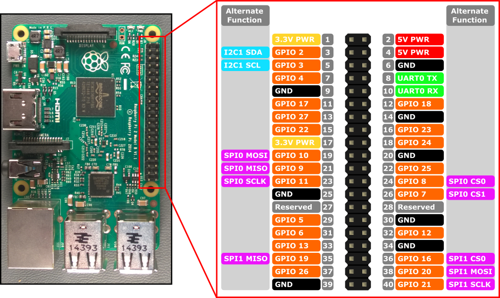
4 years ago

This library uses physical pinout mapping. GPIO17 becomes 11. You were trying to open pin 17 which is a power pin so it throws an error. Consult the pinout for further details

Pinout

muscaiu commented 4 years ago

@codedealer thanks for answering!

With the switch in pair mode i tried pins 11, 13, 15 and i got auto-detect fail on all. Any suggestions? Maybe i should change something here? Livolo.sendButton(6400, 120); As i mentioned before i have no clue how those codes work.

pins

codedealer commented 4 years ago

Judging from your picture it looks like you have a transmitter wired incorrectly, in particular power goes to data pin for some reason? Please recheck that wires are connected properly, then try writing from pin 11 again.

muscaiu commented 4 years ago

Would the pins in this diagram be correct? https://www.piddlerintheroot.com/rf-433-mhz/

I rechecked the labels and pins and took a new picture: IMG_20200322_223009

I think the pins are ok, since it works with the python code. Please look at the proof: https://vimeo.com/399711675

codedealer commented 4 years ago

I don't know how does it work in python, in the scheme you linked the wiring is different. You have mixed up data and vcc wires which basically means instead of transmitting a binary sequence you transmit a steady uniform signal (by giving 5V to the data pin) and turning on and off the transmitter rapidly (by giving binary sequence to vcc pin).

The black wire which is power should go to the middle pin on transmitter, the white wire (physical pin 11) should go to the left pin. Consult the scheme you linked again.

muscaiu commented 4 years ago

@codedealer thanks for having patience and responding.

I switched the white and black wires like you said:

IMG_20200324_202058

codedealer commented 4 years ago

Yep, that's the issue. You have rpi 4 which is not supported by this version of library. Can you check if the simple dependency update will work? Edit the line in package.json to contain "rpio": "^2.1.1" which is the latest rpio available right now. Then update the library through npm update. Now it should have rpi 4 in its hardware list.

If it works, I'll update the library.

muscaiu commented 4 years ago

Wow man i didn't have rpio installed at all. You should update the Readme to make sure ppl install it. I installed 2.1.1 and now i'm getting:

Pin: 11
sendButton: remoteID: 6400 keycode: 120

But the switch is not changing the state. I tested on 2 swicthes same thing.

Edit: I suppose i'm should add some of the codes mentioned in the readme, but like i said i have no clue how they work. Please give me an example of how could i change the state for 1 or even better multiple switches :D

codedealer commented 4 years ago

rpio installs automatically when you install livolo package so you don't have to install it by yourself normally. The old version just didn't support rpi 4 which is the problem in your case.

The warning is gone so I'm taking it is working as intended. remoteID is the id of the virtual remote control. There are two types: small ones with 4 buttons and fullsized ones. 6400 is the id of a fullsized one. You can see the keycodes for fullsize remote in the very bottom of a readme. keycode is the id of a button on a given virtual remote control, so one remoteID has several valid keycodes, all of them are listed in the readme.

The typical workflow is the following:

  1. set your switch in learning mode.
  2. send a command from rpi with a chosen args, e.g. remoteID: 6400 keycode: 120 which corresponds to fullsized virtual remote control and button no. 3.
  3. if the switch received the signal it should memorize your remote now. To change the state of the switch from now on you will send these args remoteID: 6400 keycode: 120
  4. if you have another switch you wish to pair, pick another button on the remote, for example remoteID: 6400 keycode: 96 would correspond to button no. 2 on the same remote.

You can continue adding switches to the same remoteId while you have valid button codes (in the readme). If you exhaust all of those you can always switch to a new remoteId and continue from step 1 with it.

The advantage of having all your switches on one remoteId (although you don't have to) is that you can send remoteID: 6400 keycode: 106 which corresponds to OFF button and turn off all the switches that were paired to that remoteId simultaneously.

muscaiu commented 4 years ago

Thanks for the awesome explination man! I managed to have 2 switches working, which was my goal, still have some more tests to do, maybe i will add more questions in another thread if i have any.