daneski13 / Junco

Junco, an ergonomic split keyboard with rotary encoders. Powered by Raspberry Pi Pico
CERN Open Hardware Licence Version 2 - Permissive
8 stars 1 forks source link

Can the diode between VBUS & VSYS be removed? #3

Closed JellyTitan closed 4 months ago

JellyTitan commented 7 months ago

I used the Junco circuit to build a Sofle variant. When reviewing with a thermal imager, i noticed the hottest bit of the board was the diode between the VBUS and VSYS pins. I suspect the Junco has a similar issue, but I've not validated. image

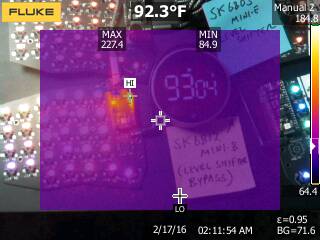
According to the Pico docs, there is an internal diode between VBUS & VSYS already? image

Was that diode added to the Junco to support a specific Pico clone that does not have the diode between vbus & vsys? If not, have you tried removing it?

daneski13 commented 7 months ago

Apologies for the late response, been very busy the last several months finishing up my last year at University. Junco was designed to be agnostic about which side of the board is plugged in and I don't entirely remember what the reasoning was for that diode just that it had something to do ensuring no issues in the event a pico clone didn't already diode it. If only one side of a split is meant to be plugged in you could easily omit it.

92F isn't a concerning temperature and is lower than body temperature. As far as I know, most diodes are designed to operate with recommended bounds of around 212F but I've heard some have absolute limits of 175C (upwards of 300F) with specific upper limits dependent on the model. Since a USB is only pushing 5V through that thing I wouldn't be concerned about temps at all.

Honored I contributed to another design.

Also, I noticed you linked to a key-swap issue which reminded me of an oversight in my original wiring for the right side's thumb keys that was fixed by swapping the keys in QMK's firmware. I haven't had a chance to finish building your revision, so do you know if the right side's thumb keys were acting "odd" with your revision? Looking at your revision of Junco I believe it fixed my mistake and I haven't pushed swapping it back in QMK.

daneski13 commented 7 months ago

On that note re your board's key swap, if you based Sofle-Pico's firmware on Junco's that would've been my fault 🤦

JellyTitan commented 7 months ago

No worries! Your design is sound! (Congrats on finishing up uni BTW). I think I got things figured on that particular diode. It looks like the official version of the Picos do have a diode between vbus and vsys -but some clones do not! IMG_1775 IMG_1776

When using clones, the power for both boards is all flowing through that single diode. Based on this video, it looks like using a 1N5817 Shottky diode there might be a better choice, as opposed to an in4148.

Thoughts?

(Thanks for looking at the keyswap keyswap issue - turns out it was an easy config fix!)

daneski13 commented 7 months ago

Thanks! Not quite out of the woods yet, in the last semester.

Yes, a Schottky diode would be the proper choice, but then it makes for yet another part to source. The voltage drop from a 4148 isn't significant enough to really cause any issues, especially since the other Pico runs at 3.3V anyway. I remember my brother noticed a slight dimming of the "slave" side's LEDs on his build when every single LED was set to white at maximum brightness (i.e. worst-case scenario for LED voltage draw) but I don't remember if re-soldering the diode for a better connection or decreasing the brightness by a smidge from max did the trick. Possibly could be a noticeable issue if someone used big boy 12ma SK6812MINI-E and blasted the brightness rather than the recommended 3ma SK6803MINI-E.

The thumb-key mistake I was referring to was this bugger on my original wiring (at least I think that was the mistake if such a mistake ever existed in the first place):

Screenshot 2024-01-07 at 7 47 56 PM

I did this to the QMK config to make it work properly, you can see it goes 34210 instead of 43210 like the left side's:

Screenshot 2024-01-07 at 7 57 42 PM
JellyTitan commented 6 months ago

Thanks! Getting the VIA config working made me go over everything with a fine tooth comb. I ran some experiments, and it looks like changing that diode can make it run up to 30 degrees cooler. I totally get the design choice to simplify the BOM by omitting an extra diode though. image

JellyTitan commented 6 months ago

I had the Junco case off today, so I took a pic. Nothing actionable, just sharing because it's interesting. It looks like it's hitting 140F on the diode. I saw high around 130F on the MCU. Do with this information what you will. IR_00039 IR_00038