decadenza / SimpleStereo

Stereo vision made Simple
GNU General Public License v3.0
40 stars 15 forks source link

Problem with Stereo Rectification. #5

Closed LightCannon closed 1 year ago

LightCannon commented 1 year ago

Hello. Thanks for this awesome work.

I have question related to Stereo rectification. First, I'm using calibration parameters from Matlab, so I modified the calibration function to hardcode the calibration parameters I have from Matlab calibration app (of course after putting the matrices in the OpenCV notation, since there is a slight difference between notations in Matlab and OpenCV). Now, cameras intrinsics, system extrinsics, fundamental and essential matrix are exactly same as matlab.

Then, I moved to rectification point. I was expecting to see the same result, which is not happening.

Here are the output rectified images using simplestereo: Left:
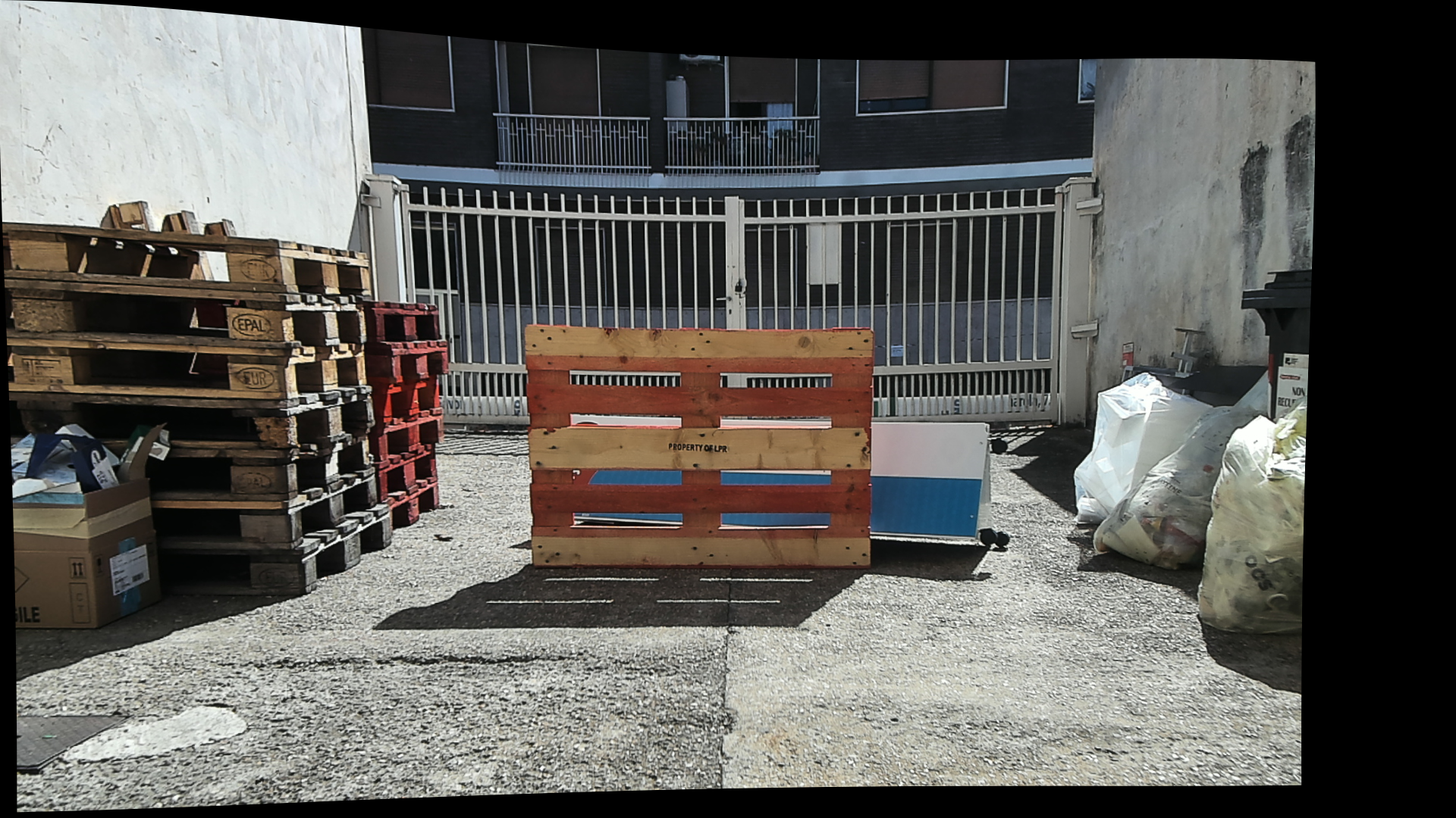
 k1

Right: k2

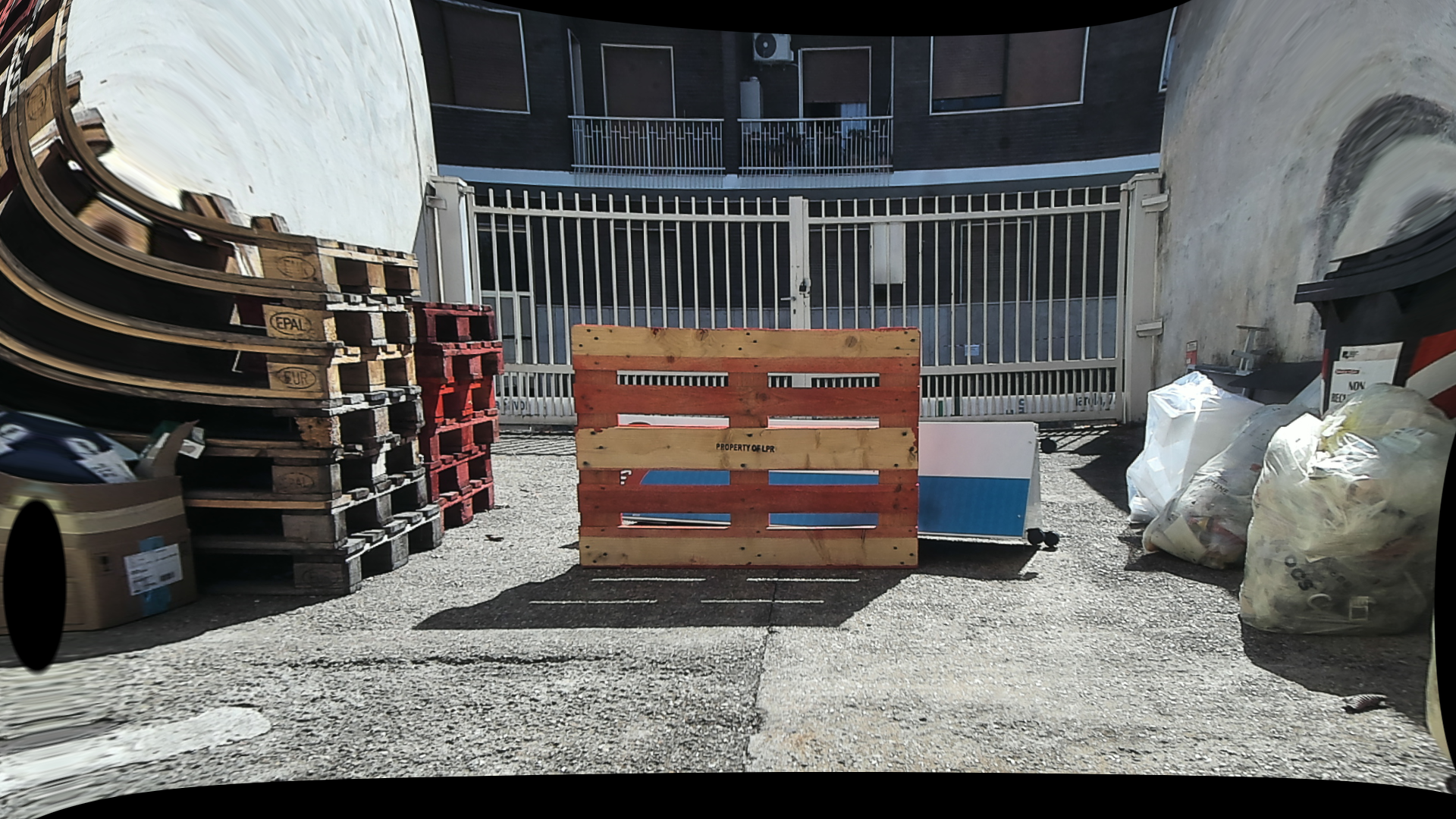
However, these are the ones from Matlab: Left:
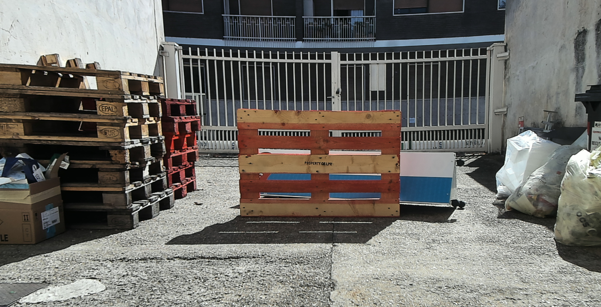
 k3

Right: k4

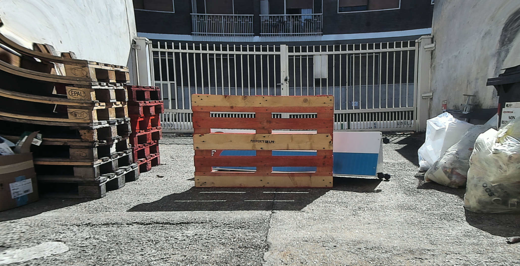
It is clear that they are quite close, but disparity wise, they are not. Take any point on the fence (L, R), from rectified images, calculate the difference in X. Take another point on the wooden box (L and R coordinates also) and get x difference.

You will find that in matlab ones, delta x for close objects are higher than far object (fence). While in Simple stereo one, delta x on fence is larger than on any closer object. This means that there is problem in disparity giving wrong depths.

I'm quite sure of matlab ones since I distances I get from rectified images from matlab matches my measurements on real world. I'm not sure where is the problem in SimpleStereo, but I doubt it is around computeRectificationMaps. I hope you can guide me what to do regarding this. Thanks in advance.

decadenza commented 1 year ago

On first sight, I can tell that the difference you are describing is related to an affine transformation applied after rectifying.

If you look the Matlab result, right image, you can notice that the red/white stripes on the bin are cut out while SimpleStereo does not take this decision for you, but you can call the computeRectificationMaps of the RectifiedStereoRig class changing the zoom parameter (which changes the intrinsic matrix of the rectified camera pair).

See this line https://github.com/decadenza/SimpleStereo/blob/20042efdc627a28ead02e39d9aa244f127ed8cf4/examples/006%20RectifyImages.py#L23

Anyway, even if disparity is different, in both cases the final 3D points should be the same because you use corresponding intrinsics.

Hope this helps. If you share some code with a specific issue I can try to help.

LightCannon commented 1 year ago

1- How can I determine this Zoom parameter automatically? cuz this will differ from image to another. 2- The problem is not the disparity is different, but it is un-logical. Far objects should have disparity values less than near ones. I'm not trying to make a 3D ply, just measuring distances, and this depends on getting right disparity values.

decadenza commented 1 year ago

1 - Well, the library automatically finds the optimal affine transformation to cut out most the black area. See the docs and the code here https://decadenza.github.io/SimpleStereo/simplestereo.html?highlight=rectification%20getfittingmatrices#simplestereo.rectification.getFittingMatrices

The point is that greater zoom means you are cutting out parts of the images (without knowing if you are going to need them for stereo matching).

2 - Can you provide examples of higher disparity for farther objects?

P. S. Disparity alone, without an associated camera matrix and triangulation, cannot give a metric distance.

LightCannon commented 1 year ago

For instance, get the left and right coordinates of the white door handle (make sure to select same corresponding pixel, same y value). and calculate disparity do the same with the brown object (which is closer). You will find the disparity (uL-uR) for brown object < (uL-uR) for door handle

LightCannon commented 1 year ago

Another note, I'm not trying to calculate distance from only disparity, but I'm doing a sanity check to make sure at least I have no problem. Depth and Disparity are inversely proportional. So, if real world object has more depth, it should have less disparity.

decadenza commented 1 year ago

Please share the original calibration parameters and the original images.

I suspect that there is an error somewhere in those.

LightCannon commented 1 year ago

Okay, Here are both 1- Hardcoded parameters (got from matlab), and I quite trust them since matlab seems to map chessboards to their right depths. ` fx2 = 817.353463664637 fy2 = 827.437071643833 cx2 = 973.296915312325 cy2 = 773.440377394847

intrinsic1 = np.array([ [fx1, 0  , 0],
                        [0  , fy1, 0],
                        [cx1, cy1, 1]]).T

intrinsic2 = np.array([ [fx2, 0  , 0],
                        [0  , fy2, 0],
                        [cx2, cy2, 1]]).T

T = np.array([-111.376420478923, 0.747349071362272, 2.68975402947472]).T

R = np.array([[0.999827957840816, -0.00748484081418036, 0.0169715019326282],
              [0.00745231227373816, 0.999970272678282, 0.00197909107862804],
              [-0.0169858105970105, -0.00185227365936933, 0.999854015004517]]).T

E = np.array([[0.0328160169488911, -2.68819499841159, 0.752222130150443],
              [4.57951641379107, 0.240468967106554, 111.314473540186],
              [0.0864142819235885, -111.378679034897, 0.218993939703964]])

F = np.array([[4.92164954260581e-08, -3.97962669268735e-06, 0.00383424227344282],
              [6.78452380805730e-06, 3.51653979973043e-07, 0.127631330619630],
              [-0.00518939660583373, -0.131168720651363, -2.02123434873081]])

distCoeffs1 = np.array([-0.0622502653431778, 0.00962675077086464,0.00653372402892466, 0.00200445202397278, 0.00114544071011637])
distCoeffs2 = np.array([-0.0766647036939572, 0.0436942578246039,0.00604871398903622, 0.000485882434697478, -0.0219259821569626])

`

Note that the transpose in cameras intrinsics is to convert them to OpenCV notation (transpose is needed between both).

Here are the original images I'm trying to measure objects in: Left: 3

Right 3

LightCannon commented 1 year ago

This is also the calibration boards' depths that Matlab computed after calibration. image

decadenza commented 1 year ago

Hi. I am still missing cx1, cy1, fx1 and fy1 values.

LightCannon commented 1 year ago

sorry, my bad fx1 = 815.765387429049 fy1 = 826.434666377440 cx1 = 978.132348923286 cy1 = 744.308043953343

fx2 = 817.353463664637
fy2 = 827.437071643833
cx2 = 973.296915312325
cy2 = 773.440377394847
LightCannon commented 1 year ago

Another note, I'm not sure if it is useful or not.

I computed the Rectification out of Matlab, but I used "full" instead of "valid". The rectification images are exactly same as ones I'm getting from the library, except for one thing, they are "some sort of" concentric. In another words:

This is the rectified images from Matlab, but using stereoAnaglyph function to put them over each other. k5

and these are the individual images rectified images from Matlab(left then right) k3 k4

Comparing both with rectified images I'm getting using the library (left then right) k1 k2

it is clear that the left images are not in same alignment (Matlab's Left has some translation different from library's left). I suspect that the reason for this lies in these lines (https://github.com/decadenza/SimpleStereo/blob/d66f9acd2b862f8d61672556edb9c3cd031757ba/simplestereo/rectification.py#L17) since you mentioned that you always keep image to left and top. I'm not sure this is the reason or how should I fix (since I don't understand that part) + I'm not sure if this is a reason for strange disparity.

decadenza commented 1 year ago

Here I am!

I found the issue and I am going to try to explain.

After rectification, you can (and must, for visualising) apply arbitrary affine transform to the images. In SimpleStereo I use getFittingMatrices to find those. While MATLAB and other standard approaches choose the same matrix, say K for both left and right, in SimpleStereo I am using two different matrices K1 and K2 which are exacly the same, except for a translation over the X-axis (which does not change rectification). You may print them as rigRect.K1 and rigRect.K2. If used correcly, the disparity is calculated taking this shift into account, so that everything is fine.

Anyway, I understand that this degree of freedom is actually awkward, so I am going to remove this.

Here is the code I used

import numpy as np
import cv2

import simplestereo as ss

# Read right and left image (please ensure the order!!!)
img1 = cv2.imread('left.png')
img2 = cv2.imread('right.png')

# Raw camera parameters (as NumPy arrays)
fx1 = 815.765387429049
fy1 = 826.434666377440
cx1 = 978.132348923286
cy1 = 744.308043953343

fx2 = 817.353463664637
fy2 = 827.437071643833
cx2 = 973.296915312325
cy2 = 773.440377394847

# Left intrinsics
A1 = np.array([[ fx1,   0, cx1], 
               [   0, fy1, cy1],
               [   0,   0,     1]]) 

# Right intrinsics        
A2 = np.array([[ fx2,   0, cx2],
               [   0, fy2,cy2],
               [   0,   0,     1]]) 

T = np.array([[-111.376420478923], [0.747349071362272], [2.68975402947472]])

R = np.array([[0.999827957840816, -0.00748484081418036, 0.0169715019326282],
              [0.00745231227373816, 0.999970272678282, 0.00197909107862804],
              [-0.0169858105970105, -0.00185227365936933, 0.999854015004517]])

# Distortion coefficients
distCoeffs1 = np.array([-0.0622502653431778, 0.00962675077086464,0.00653372402892466, 0.00200445202397278, 0.00114544071011637])
distCoeffs2 = np.array([-0.0766647036939572, 0.0436942578246039,0.00604871398903622, 0.000485882434697478, -0.0219259821569626])

# Create the StereoRig
rig = ss.StereoRig(img1.shape[::-1][1:], img2.shape[::-1][1:], A1, A2, distCoeffs1, distCoeffs2, R, T) 

# Build the RectifiedStereoRig
rigRect = ss.rectification.directRectify(rig)

# Save it to file
#rigRect.save('stereoRig.json')

# Rectify the images
img1_rect, img2_rect = rigRect.rectifyImages(img1, img2)

# Show images
cv2.namedWindow('LEFT rectified', cv2.WINDOW_NORMAL)
cv2.namedWindow('RIGHT rectified', cv2.WINDOW_NORMAL)
cv2.imshow('LEFT rectified', img1_rect)
cv2.imshow('RIGHT rectified', img2_rect)
cv2.resizeWindow('LEFT rectified', 800, 600)
cv2.resizeWindow('RIGHT rectified', 800, 600)

cv2.waitKey(0)
cv2.destroyAllWindows()

Regarding the black border. SimpleStereo by default uses the MATLAB equivalent of OutputView='full', so that all the pixels are preserved in the image.

Given your input, I am going to open a new issue to add a new feature in SimpleStereo to behave like the valid option of MATLAB, so that "the output images are cropped to the size of the largest common rectangle containing valid pixels." (source).

decadenza commented 1 year ago

The originating issue has been solved and changes pushed to master.

A separate feature request will be created to implement the "valid" strategy.

LightCannon commented 1 year ago

Seems I didn't get you well. What is the solution in your estimation to fix the disparity problem?

I understand that you are using two different matrices while Matlab uses one (and I think my matlab vs opencv comment also proves this is right). But in order to measure distances (like wooden box dimensions), I need to make sure disparity is right.

May you explain how this code solved the problem? Basically I'm doing all of this to measure distances (not only depth) so having right disparity (and reasonable one) is critical.

Thanks a lot, and waiting for any additions from you.

decadenza commented 1 year ago

If you ran the code above with the updated version of the library, you get the following two images (left and right, respectively):

left_rect right_rect

You can see that the disparity now has no shift, and in the left image the tip of the handle is around x=892, while in the right image is around x=871.

If calibration is good enough, disparity is right. After a stereo matching algorithm finds corresponding pixels, you need to do triangulation and calculate 3D points, like this demo.

Then you can take all the measures that you want.

LightCannon commented 1 year ago

I see, I'm not doing correspondence manually, since I'm having troubles with adjusting parameters for the SBGM,..etc.

A question I have is how can I make sure my calibration is good enough?

decadenza commented 1 year ago

Usually a reprojection error < 1 is a good indicator (but not absolute), please search online you will find plenty of explanations about single camera and stereo camera reprojection error. This is only an issue tracker for the library. However, you need to collect ~100 chessboards to obtain robust results. But this has to be done only once (if you don't move the cameras ;-) ). Cheers.

LightCannon commented 1 year ago

One final question related to library (not sure if it needs a new issue or not) The Q matrix has quite different definition from what I see online. For instance, Q[2,3] has -ve sign in the library while function like cv2 stereo rectify gives Q which has element [2,3] a +ve.

Is there a certain reason for this? any source for understanding the definition you wrote in the library?

Thanks a lot.

aaronlsmiles commented 1 year ago

EDIT: I will reference this in a new issue as I see this has been closed off!

Great thread, very useful, thanks guys!

@decadenza I have a few questions relating to your comment above:

1

Usually a reprojection error < 1 is a good indicator (but not absolute)

I am struggling to get a reprojection error (RPE) <1 .

I am using a 7x6 checkerboard printed on A4 paper and glued to a clipboard, and x2 AKASO EK7000 action cams in 4K 30fps video mode, syncing the left and right video in Premiere Pro, then extracting the still frames*. I have been using ~30 images pairs like your example, but the best RPE I've got so far is 1.29.

I've tested the code with your examples/calib image folders and notice that your images have no distortion, yet mine you can see (below) have barrel distortion. Have your calib image folders been run through the "004a UndistortImages.py" code and should I do the same to my images (then calibrate again)? Is this the practice for improving the RPE, or should I been getting a better initial RPE before doing any undistort actions?

Or, could the fact that I've rescaled the checkerboard be causing issues (as it looks like the checkerboard you use in the calib image folders is larger than mine)?

14_L 14_R *I am calibrating this way instead of using your code because I will need to perform this underwater for my research and will not be able to have cameras connected to the computer.

2

However, you need to collect ~100 chessboards to obtain robust results.

Your code uses/suggests 30 images. Should we be collecting 100?

3

Lastly, when you say:

But this has to be done only once (if you don't move the cameras ;-) ).

Do you mean the distance/position between the cameras? I have both cameras fixed to a ruler at 10cm apart. The idea is to move this stereo camera pair around for robot navigation research. To clarify, this will be ok and not require recalibration every time the camera pair move together, correct?

decadenza commented 1 year ago

One final question related to library (not sure if it needs a new issue or not) The Q matrix has quite different definition from what I see online. For instance, Q[2,3] has -ve sign in the library while function like cv2 stereo rectify gives Q which has element [2,3] a +ve.

Is there a certain reason for this? any source for understanding the definition you wrote in the library?

Thanks a lot.

I made all the calculations from scratch to include shear parameters and different fx and fy, and this is the result. Probably the minus sign on row 3, compensates from different signs on row 4.

As showed in the examples, the final 3D reconstruction is working. If you find any problem specific problem, please open a new issue! I am trying to maintain this library as much as possible.