dekuNukem / Nintendo_Switch_Reverse_Engineering

A look at inner workings of Joycon and Nintendo Switch
3.44k stars 194 forks source link

Gyroscope/Accelerometer Status #18

Closed afiaka87 closed 6 years ago

afiaka87 commented 7 years ago

I saw that you managed to get the data from the SPI for accelerometer/gyroscope.

Upon connection the microcontroller initializes a software reset of the MEMS chip, then set up the accelerometer and gyroscope as follows: ... Since the Joycon polls MEMS data every 1.35ms but only send out controller update every 15ms, there might be some internal averaging to smooth out the data, needs to go through the numbers to find out.

Is this something you've only been able to capture directly from the SPI?

I think it's been established that the joycons don't send accelerometer and gyroscope information without some sort of command being sent to the joycon. Is this accurate?

If so, is there any speculation as to what the command is currently or how to discover it?

disclaimer: I've seen this question asked a lot in other issues but I'm a bit of an outsider to all of the low-level reverse engineering skills this project requires. Please forgive any misunderstandings.

shinyquagsire23 commented 
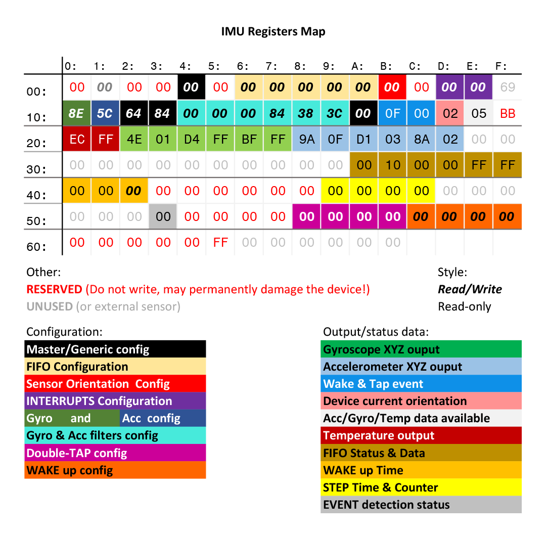
7 years ago

I've found with my weird racing tactic in a charging Joy-Con grip (having it connected over Bluetooth and then quickly switching to USB/UART) that input packets send additional data which looks to be gyro/accelerometer data, so it's mostly an issue of enabling the IMU.

afiaka87 commented 7 years ago

Again, forgive my ignorance. Are the packets you're seeing doing the enabling being sent by bluetooth before the switch, or by USB/UART after the switch. Do you have a dump of those packets? Would love to have a look at them

fossephate commented 7 years ago

I believe @shinyquagsire23 is referring to connecting the JoyCons to the switch over bluetooth, and then quickly connecting over USB, which let's you poll for gyroscope data / rumble; More testing is definitely needed to get a better understanding though.

shinyquagsire23 commented 7 years ago

Found the commands to enable IMU data over input packets,

80 92 00 31 00 00 cb 8f 01 04 00 01 40 40 00 01 40 40 40 01 00 00 00 00 00 00 00 00 00 00 00 00 00 00 00 00 00 00 00 00 00 00 00 00 00 00 00 00 00 00 00 00 00 00 00 00 00 
19 01 03 38 00 92 00 31 00 00 cb 8f 01 04 00 01 40 40 00 01 40 40 40 01 00 00 00 00 00 00 00 00 00 00 00 00 00 00 00 00 00 00 00 00 00 00 00 00 00 00 00 00 00 00 00 00 00 00 00 00 00 

First line is what you'd send via charging grip or to a Pro Controller over USB, second is just what is sent over UART.

aspalmer commented 7 years ago

Have you tried this over BT?

afiaka87 commented 7 years ago

An update on this would be awesome. I'm desperate to get that data over bluetooth. Not sure how much work needs to be done but we could close out this issue hopefully.

Unrelated - is it correct that the Joy Cons communicate over Bluetooth even if they're in the Switch after an initial pairing?

dekuNukem commented 7 years ago

Joycon only use bluetooth when it's detached from the console. if it's attached to the console it uses physical serial communication instead.

riking commented 7 years ago

@claymullis This is the command to enable the IMU: https://github.com/riking/joycon/blob/master/prog4/joycon/bluetooth.go#L102

wormyrocks commented 7 years ago

Has anyone else done this yet?

CTCaer commented 7 years ago

So you've managed. It looks great and so smooth!

Are you planning to support up/down, left/right, forward/backwards movement also?

sniejadlik commented 7 years ago

@wormyrocks Great job! I have been waiting for someone to get that working in Unity beyond just the buttons as was easy to do previously. I also had analog sticks working in the editor but not on deployment. What were the steps needed to read the accel / gyro data?

wormyrocks commented 7 years ago

@CTCaer Yes - the equations I am using now give position and rotation - but right now my gyro data does not work well enough to look good when visualized. I saw that you did some digging into the gyroscope calibration values, that will be really helpful as I was mostly guessing when I did the initial integration.

@sniejadlik This is literally my first Unity project, so I don't know how to handle flow control at all. Since the Joy-Con pushes IMU packets every 15ms and has a sizable FIFO buffer, if it is polled any slower than it produces data the buffer will quickly saturate, leading to a lag time of a few seconds between movement and response. So the demo looks nice, but when it is implemented in a project with a locked frame rate it totally chokes. Once that is fixed and my gyro data gets a little more accurate I will publish the code! If you want to integrate before then, the information used is all here. For Unity integration I used the HIDapi libraries from here.

@CTCaer any suggestions on the best steps to take would be to prevent the buffer from saturating? My first instinct is just to rewrite my code to keep hid_reads in their own thread, and try to keep them as regular as possible at 15ms. The trouble then is that I suspect I will run into synchronization issues if I want to send rumble data or other subcommands after the polling thread begins.

sniejadlik commented 7 years ago

@wormyrocks good to know. I actually can't build anything right now as I was using my coworkers joycons the last time I was experimenting with this. I'm planning on buying a pair now just to experiment now that it looks like the integration is starting to work.

As far as timing is concerned, is the issue that Unity is not giving you a consistent interval to poll with? Are you just trying it on the Update command? You could try creating a coroutine possibly and tie the timer to the Time.deltaTime in order to get an accurate time stamp. Not sure if that helps but just trying to think through possible issues with request functions tied to Unity's framerate.

CTCaer commented 7 years ago

@wormyrocks Hmm.. Well first of all, yeah, packet parsing and acc/gyro parsing must have their own thread. So you can queue packets and parse them asap. This will need a 2nd queue also that the other thread will keep the parsed timer and acc/gyro samples.

2nd use bit masking/operations and matrices to optimize the big math functions.

3rd is to have a global timer that you can check and correct the time your packet came to the expected time. The best way is to use the packet timer (2nd byte after the x30 id). Actually switch, uses this packet timer. Every 1 increment is 5ms. So you will see +3 in your packets. If that time is bigger than 15ms, then you just need to parse acc/gyro but drop the drawing. Then you do the drawing of the next packet that is calculated based on the previous one. This way, it will seem like it skipped frames and your cube jumped to the new position, but you will have the correct position. All software that I tested in switch, worked like this. They made jumps but kept the correct position. If you really lost a packet, let's say 2nd packet, then a median (1st + 3rd)/2 can do the job.

After reaching a good optimization you can then go to a delta of 5ms (instead of 15ms), by parsing all 3 acc/gyro samples in the packet.

EDIT: I want to stress that the hid_reads on their own thread should be blocking. You must not have a timer there. Just blocking hid_reads and a seperator logic that uses the button/stick data right away or sends them to a button/stick thread and queues the timer and acc/gyro for the acc/gyro parsing thread to work on them.

wormyrocks commented 7 years ago

@CTCaer I am looking at your updated IMU documentation. Can you explain how you arrived at the conclusion that the gyroscope scaling coefficient is 13371dps? I understand that that value is found in the SPI calibration memory location - but, according to the IMU datasheet, the maximum range is only 2000dps.

I have been trying to figure out how the sample gyroscope readings provided in table 4.5 in the datasheet - table 4.5 - are supposed to be interpreted, to get some clue as to how to process the data found from the Joy-Con gyroscope. However, the obvious solution (sample * 245 / 32768) does not yield the corresponding value. I must be missing something here.

Interestingly, when I test your equation for the gyroscope vector component, it gives me something very very close to the number of rotations per second, rather than degrees per second. In my Unity implementation, if I monitor a running sum of dt gyro 0.000204f and rotate the Joy-Con one full revolution in that axis, my sum is very close to 1. so I think your answer may just be in the wrong units.

I am still not sure where the math in the datasheet came from. Nor the magic numbers in the implementation I originally used

CTCaer commented 7 years ago

@wormyrocks My fault here is that because I work on RE stuff + trial and testing, I always mix the things up and also forget to document everything. So yeah, for Gyro, Switch calculates directly rotations/s. And what I wrote is this exact thing, not dps.

First of all, I will update the whole thing, and I hope that you will help us add every other equation (angles, etc).

Let's see now why Switch uses these number instead of 2000dps and 8G.

Acc We can easily find the sensitivity with 2 different ways. One is the one you did. Start calculating when still on an axis until you managed to produce a 1G value. The other way, per 4.6.1 in datasheet , is to leave the device on one axis, measure, turn 180 degrees and measure again. Subtract the smallest from the biggest and divide by 2. We again see 65535/4000/2=16G sensitivity range, or ±8G.

But, Switch uses a ±8192 mG (0.25mG/LSB) sensitivity for some reason. Maybe because it's a power of 2? The change is small though, along the lines of 2.5%. Other than this, I don't know why it uses that value.

We also see that the datasheet has the correct values for mG, for Joy-Con it's 0.244 mG/LSB.

Gyro The only way to measure gyroscope sensitivity is by tying the device on a motor or a wheel that we know it's RPM when it moves. But, you already tested it and found out that with my equation, you did one revolution and showed ~1 revolution.

So what are these strange values from the calibration data and also from the datasheet? As you found out, the Joy-Cons are default 2000dps sensitive. So 2000*2/65535 is 0,061 -> 61mdps/digit. Hmm.. why 70 then? As this guy nicely explains, "to make sure that the useful (linear) part of the analog sensor range always falls within the ADC range despite manufacturing tolerances, they gave a 15% margin (7.5% to each end)". "The "extra" range of the digital output allows the sensor to express the full-scale rates in both directions without saturating, even when these errors all add up in the same direction."

STMicroelectronics: 61+15%=70. Or ±2294dps.

So what about the 13371 from Nintendo? First, let's convert it to mdps/digit. 13371/65535*360=73.44. We can see that 61+20%=73. Or ±2406.5dps. So basically, Nintendo went the extra mile to add a 20% margin instead of STMicroelectronics' 15%.

I don't know where the magic numbers came from that function there, but I assume with some calculations we can find out.

Anyway, I hope that we now cleared up the mist. It's all about manufacturer decisions and, personally, mixing things up.

CTCaer commented 7 years ago

@wormyrocks Please review this and tell me if there's something I must change.

Also I have another question:

It seems that some axes are inversed in Gyroscope too:

Which one is correct?

wormyrocks commented 7 years ago

for the gyroscope, I get the same axes as you show in the diagram except that the Z-axis on the left Joy-Con is reversed.

here is the eqn I used to get consistent axes of rotation on both Joy-Cons:

gyr_r[i] = (Int16)(gyr_r[i] * ((isleft & i>0) ? -1 : 1));

where i=0 : x, i=1: y, i=2: z.

Interestingly, I get that the gyroscope coefficients are different on the left and right Joy-Cons. at least for my own set of Joy-Cons it looks like the left Joy-Con uses the STM default multiplier and the right Joy-Con uses the Nintendo coefficient for higher dynamic range. so, I am now normalizing to give degrees with the following equation:

gyr_g[i] = gyr_r[i] * (isleft ? 0.061f : 0.07344f);

also this documentation is fantastic. thanks for putting in all this effort

CTCaer commented 7 years ago

You are welcome.

Hmm. I updated the picture. I had the X/Y acc axis wrong for left joycon. These are final and correct. I removed the info on reversed axis now that the schematics are correct. (+Axis away from ground = 1G output). So now, gyroscope values also match the right hand rule.

About the gyroscope coefficients, it's strange. Did you calibrated them? Because both of them are configured with +/-2000dps, so they work on the 0.061f coeff. STM (0.07) and Nintendo (0.7344) coeff are only to protect from saturation.

Now I'm trying to finalize the origin position SPI calibration.

wormyrocks commented 7 years ago

BTW, I ordered an LSM6DS3 developer kit which I might use to analyze the raw data coming from the IMU. let me know if you have any requests for any sort of data dumped from there. command outputs, calibration data, etc. I'll probably just use the Arduino library and look at the raw data output. If any of the Joy-Con subcommands let us send commands directly to the accel/gyro, it would be really cool to try and enable pedometer mode or motion sensor mode. Then people could use a Joy-Con + Raspberry Pi W, for instance, to build a security system or something similar.

CTCaer commented 7 years ago

There are some commands, x41/x42/x43. Maybe analyzing how to send them from your dev kit can help us figure out the format in the jc subcmd.

Also, I hope for the temperature here.

wormyrocks commented 7 years ago

So I have double checked the gyro coefficients on the left and right Joy-Cons and I am pretty sure that the actual range is +- 2000 dps. I've rewritten my Unity library to poll with threading and numerically integrate with dt=5ms, and checking the timestamps on the input report I can actually be sure that I am processing every single packet sent by the Joy-Con. With this method I actually get a completely accurate rotation value (both Joy-Cons are the same) if I use the multiplier 0.061f rather than 0.07344f. Perhaps our Joy-Cons are calibrated differently from each other?

CTCaer commented 7 years ago

No no, there is no problem with your calculations. They are correct. The device as I said is configured at +/-2000dps. WE just calculate the digital output differently. In almost all applications I saw, they were using 0.07f which is the one STM proposes. Even though the device was configured at 2000dps (0.06103f).

As I described before, we do this to avoid saturation when the values are out of range. For example, we have set it to +-2000dps range, But because of how acc and their internal ADC scaling works, they can still catch a value of let's say +2300dps or +2400 and output it as 2000dps. So to avoid saturation from these cases, we can use a margin of 15% or 20%.

The article I linked explained this:

So my question is this. If the gyroscope is configured in the +/- 250dps (degrees per second) range how is it that the sensitivity is only 8.75 mdps/digit? I would expect that the sensitivity would be 0.007629dps or 7.629mdps/digit. I calculate this as follows: 500/65536=0.007629 dps or 7.629mdps/digit

How do you calculate the mdps/digit? and where am I going wrong?


The manufacturer wanted to make sure that the useful (linear) part of the analog sensor range always falls within the ADC range despite manufacturing tolerances. To that end, they gave themselves a 15% margin (7.5% at each end). This would agree with some of the other numbers in the datasheet, such as initial offset (DVoff) of +/-4% and a worst-case temperature offset (OffDr) of +/-2.4% at the extremes.

In other words, this sensor needs to be calibrated (zeroed) and temperature-compensated (for both offset and gain) in your application in order to achieve the best level of performance. The "extra" range of the digital output allows the sensor to express the full-scale rates in both directions without saturating, even when these errors all add up in the same direction.


It is true you could possibly get a reading of 286, but that's something you should treat as an 'out of range' condition. If they made the scaling exact without an error flag of some sort you'd have no way of knowing the difference between 250 and something above that went off-scale. Most accelerometers I've used are similar and do report something above the normal range.

So, basically this means the following:

About Nintendo use:

First of all, for your usage case, forget what nintendo uses. You are not currently trying to connect the Joy-Cons to a Switch emulator, of which you are the jcpad plugin developer. But personally I want to document the Switch usage also, so: As I said the REed code points to the type of this calibration value. That does not mean it is being used though. Maybe Nintendo also uses 0.061f or STM's 0.07f. I will delve on this part today though.


A fun experiment to calculate the real sensitivity value for your room temperature: You can attach the Joy-Con on a motor and start rotating. You measure with a laser the RPM (for us the best is Rotations/s) and raise the power on the motor until you reach a x7FFF jc output. The rpm/360*60 is your real dps +-range. But there's a possibility that you can see something like a 0.1RPM or 6 rotations/s and your jc output may show lower than x7FFF.

CTCaer commented 7 years ago

@wormyrocks OK, here it is:

uint16_t gyro_raw[3];  // raw values
uint16t_t gyro_cal_xyz[3];  //origin position cal
uint16t_t gyro_cal_xyz_2[3];  //x343B is used!!

int gyro_sensitivity; // Switch can change this value via a subcmd. 250dps, 500dps, 1000dps, 2000dps.

float gyr_setting_coeff;
float gyr_coeff_xyz[3];  //final coeff that we multiply our raw value
float gyr_vec_xyz[3];

switch(gyro_sensitivity){

    case 2000:
        gyr_setting_coeff=1.0f;
        break;
    case 1000:
        gyr_setting_coeff=0.5f
        break;
    case 500:
        gyr_setting_coeff=0.25f
        break;
    case 250:
        gyr_setting_coeff=0.125f
        break;
    default:
        error_return;

}

// This is what we want to know!! What? huh? I mean, what?
gyr_coeff_xyz[0] = ((936.0 / (*((float *)gyro_cal_xyz_2[0]) - *((float *)gyro_cal_xyz[0]))) * 0.0027777778) * gyr_setting_coeff;
gyr_coeff_xyz[1] = ((936.0 / (*((float *)gyro_cal_xyz_2[1]) - *((float *)gyro_cal_xyz[1]))) * 0.0027777778) * gyr_setting_coeff;
gyr_coeff_xyz[2] = ((936.0 / (*((float *)gyro_cal_xyz_2[2]) - *((float *)gyro_cal_xyz[2]))) * 0.0027777778) * gyr_setting_coeff;

// Calibrated value in dps or rotations/s??? Probably rotations.
gyr_vec_xyz[0] = gyro_raw[0] * gyr_coeff_xyz[0];
gyr_vec_xyz[1] = gyro_raw[1] * gyr_coeff_xyz[1];
gyr_vec_xyz[2] = gyro_raw[2] * gyr_coeff_xyz[2];

This is almost exactly what Switch is doing. My god, the whole back and forth in functions is tiring... I really want to see what these values produce... Time to configure my JC toolkit.


I'm really curious what it does for acc..

riking commented 7 years ago

*((float *)gyro_cal_xyz_2[0])

That seems extremely suspicious, especially as the calibration values are uint16 and float is a float32... possible that it's ((float)(gyro_cal_xyz_2[N] - gyro_cal_xyz[N])) instead?

CTCaer commented 7 years ago

This maybe an outcome from IDA. I said not this reinterpret from uint16 to float or float16 again. Fuck it and did it the way I thought it was correct to me.

And yes, like what you proposed, I made this to my toolkit:

Setting coef is 1.0f, so skip it
gyro_coeff[0] = (936.0 / (float)(sensor_uint16_to_int16(0x343B) - sensor_uint16_to_int16(sensor_cal[1][0]))) * 0.0027777778;
gyro_coeff[1] = (936.0 / (float)(sensor_uint16_to_int16(0x343B) - sensor_uint16_to_int16(sensor_cal[1][1]))) * 0.0027777778;
gyro_coeff[2] = (936.0 / (float)(sensor_uint16_to_int16(0x343B) - sensor_uint16_to_int16(sensor_cal[1][2]))) * 0.0027777778;

So the outcome is rotations/s.

To get dps:

//setting coef is 1.0f, so skip it
gyro_coeff[0] = ((936.0 / (float)(sensor_uint16_to_int16(0x343B) - sensor_uint16_to_int16(sensor_cal[1][0]))) * 0.0027777778) * 360.0;
gyro_coeff[1] = ((936.0 / (float)(sensor_uint16_to_int16(0x343B) - sensor_uint16_to_int16(sensor_cal[1][1]))) * 0.0027777778) * 360.0;
gyro_coeff[2] = ((936.0 / (float)(sensor_uint16_to_int16(0x343B) - sensor_uint16_to_int16(sensor_cal[1][2]))) * 0.0027777778) * 360.0;

OR

//setting coef is 1.0f, so skip it
gyro_coeff[0] = (936.0 / (float)(sensor_uint16_to_int16(0x343B) - sensor_uint16_to_int16(sensor_cal[1][0])));
gyro_coeff[1] = (936.0 / (float)(sensor_uint16_to_int16(0x343B) - sensor_uint16_to_int16(sensor_cal[1][1])));
gyro_coeff[2] = (936.0 / (float)(sensor_uint16_to_int16(0x343B) - sensor_uint16_to_int16(sensor_cal[1][2])));

The funny thing is that it works and produces a coeff for each axis based on the origin position. Amazing!

So basically to calibrate we don't do (axis - origin) sens_coeff. We do a mumbo jumbo with origin and sens_coeff and then with raw cal_coeff

So, the coeff produced if the origin position is center (0x0000) it's 0,00019445*360=0,070f They really used the STM coeff like everyone else!!!

OK. I have to rework the sensor notes now!

EDIT: Added easier calculation to dps. BTW, 936/13371=0.07f!

CTCaer commented 7 years ago

Also another thing that I forgot. I confirmed that they clamp the calibrated and converted acc and gyro to (-7.0, 7.0) G and (-1800.0, 1800.0) dps or (-5.0, 5.0) rotations/s.

But we don't care about this I think.


EDIT: Also, If you still want to use the 0.061f coeff then replace 936.0 with 816,0f

CTCaer commented 7 years ago

And last but not least ACC:

uint16_t acc_raw[3]; // raw values
int16t_t acc_cal_origin_xyz[3]; //origin position cal. int16t_t
int16t_t acc_cal_magic_xyz[3]; //x4000 is used!! int16t_t

int acc_sensitivity; // Switch can change this value via a subcmd. +/-2G, +/-4G, +/-8G.

float acc_setting_coeff;
float acc_coeff_xyz[3]; //final coeff that we multiply our raw value
float acc_vec_xyz[3];

switch(acc_sensitivity){

    case 2:
        acc_setting_coeff = 1.0f;
        break;
    case 4:
        acc_setting_coeff = 2.0f;
        break;
    case 8:
        acc_setting_coeff = 4.0f;
        break;
    default:
        error_return;

}

//the cal must be already converted
acc_coeff_xyz[0] = (float)(1.0 / (float)(acc_cal_magic_xyz[1] - acc_cal_origin_xyz[1])) * acc_setting_coeff;
acc_coeff_xyz[1] = (float)(1.0 / (float)(acc_cal_magic_xyz[1] - acc_cal_origin_xyz[1])) * acc_setting_coeff;
acc_coeff_xyz[2] = (float)(1.0 / (float)(acc_cal_magic_xyz[1] - acc_cal_origin_xyz[1])) * acc_setting_coeff;

//calibrated value in G.
acc_vec_xyz[0] = acc_raw[0] * acc_coeff_xyz[0];
acc_vec_xyz[1] = acc_raw[1] * acc_coeff_xyz[1];
acc_vec_xyz[2] = acc_raw[2] * acc_coeff_xyz[2];

Note: (1/magic)4 = (1 / 16384) 4 = 0.000244f!

Oh, I'm so happy now

EDIT: Corrected the note about the coeff

CTCaer commented 7 years ago

Last note and reference usable code: So we now know that switch for default sensitivities it uses the correct coeff: 0.000244f and 0.07f and has a nice code to incorporate the calibration written to Joy-Con.

Code (for ±8G, ±2000dps):

int16_t sensor_uint16_to_int16(uint16_t a) {
    int16_t b;
    char* aPointer = (char*)&a, *bPointer = (char*)&b;
    memcpy(bPointer, aPointer, sizeof(a));
    return b;
}

// sensor_cal contains the sensor SPI calibration values in uint16t_t
// sensor_cal[0][#] -> origin position for acc when on table and still
// sensor_cal[1][#] -> origin position for gyro when still
uint16t_t sensor_cal[3][3];

acc_cal_coeff[0] = (float)(1.0 / (float)(16384 - sensor_uint16_to_int16(sensor_cal[0][0]))) * 4.0f;
acc_cal_coeff[1] = (float)(1.0 / (float)(16384 - sensor_uint16_to_int16(sensor_cal[0][1]))) * 4.0f;
acc_cal_coeff[2] = (float)(1.0 / (float)(16384 - sensor_uint16_to_int16(sensor_cal[0][2]))) * 4.0f;

gyro_cal_coeff[0] = (float)(936.0 / (float)(13371 - sensor_uint16_to_int16(sensor_cal[1][0])));
gyro_cal_coeff[1] = (float)(936.0 / (float)13371 - sensor_uint16_to_int16(sensor_cal[1][1])));
gyro_cal_coeff[2] = (float)(936.0 / (float)(13371 - sensor_uint16_to_int16(sensor_cal[1][2])));

EDIT: Simplified the equations a little bit and added sensor_uint16_to_int16() function.

CTCaer commented 7 years ago

@wormyrocks Hey, what you needed is here

EDIT: Corrected byte 0/1 and link

CTCaer commented 7 years ago

New development:

You can now completely control the IMU. Every writable register and you can read all registers.

Check here for more.

wormyrocks commented 7 years ago

Frickin awesome.

CTCaer commented 7 years ago

I'll leave that here: Alt High-res

wormyrocks commented 6 years ago

btw: https://gbatemp.net/threads/joy-con-unity-library.486629/

afiaka87 commented 6 years ago

Outstanding work to everyone that worked on this. Thanks.

emmauss commented 4 years ago

Anyone know how joycon orientation(rotation) matrix and rotation vector is derived or computed on the switch HID module?