 alejandrorangel
commented
7 years ago
alejandrorangel
commented
7 years ago I'm also working to reverse engineer the joycons, I found this documentation. I think that Nintendo might use something similar to the joycons.
Open ghost opened 7 years ago
alejandrorangel
commented
7 years ago I'm also working to reverse engineer the joycons, I found this documentation. I think that Nintendo might use something similar to the joycons.
 dekuNukem
commented
7 years ago
dekuNukem
commented
7 years ago thanks, I did figure out the accelerometer and gyroscope data in the joycon status packet today, but only in the physical connection bewteen the joycon and console. I haven't began working on the bluetooth level yet, but I'll keep it in mind when I do.
 forerofore
commented
7 years ago
forerofore
commented
7 years ago just to make you guys aware, there is a program similar to glovepie called freepie, the possibility of developing a module for the joycons may be faster/easier than an entire new driver. thanks and gj with all of this.
heres the link btw [http://andersmalmgren.github.io/FreePIE/]
 ghost
commented
7 years ago
ghost
commented
7 years ago @alejandrorangel Cool, thanks for that. I might try and throw some of the Wiimote packets at it this weekend and see if it reacts to any of them.
 aspalmer
commented
7 years ago
aspalmer
commented
7 years ago Over USB the pro controller just does a handshake, then switches to bluetooth. Descriptor: procontroller descriptor.txt Beagle analyzer trace: data-center-windows-x86_64-v6.72.zip
ghost
commented
7 years ago @aspalmer That actually makes sense from the HID reports I was getting back, actually. Was able to get the HID info from the USB device, although no data was being sent. However when I paired the USB and Bluetooth together using some test code, I noticed one thing. Over the USB, the HID protocol reports that there are 2 extra components called "Z-Acceleration, and Z-Rotation". I can only imagine this is the gyroscope and accelerometer. However, as it was over USB, no data was sent. This leads me to believe you do indeed have to send a feature report packet to the controller via bluetooth to enable the gyro/acc.
Also, via USB the HID device is reported as a "stick" or "joystick", versus the Bluetooth HID which reports as "gamepad". Can actually see this from the descriptor you sent over actually.
 rlaferla
commented
7 years ago
rlaferla
commented
7 years ago I'd love to see an iOS API for the JoyCon via Bluetooth.
UPDATE: iOS uses its own Bluetooth controller specification which means it does not work natively with the Joy-Con or Switch Pro controllers.
 riking
commented
7 years ago
riking
commented
7 years ago I have some notes on the Bluetooth hid buttons. The left stick & right stick buttons are adjacent button numbers. So are + - and home, capture.
It sends the stick data as hat input, though. (0-8, 8 is neutral, 0 is up) Annoying.
 fossephate
commented
7 years ago
fossephate
commented
7 years ago @riking What are you using to capture the Bluetooth traffic?
riking
commented
7 years ago @mfosse Oh, I just straight up connected the joycon to my Linux laptop and read the input data with hidapi. So it's default drivers.
Was about to try sending some of the 0x19 packets as OUPTUT or FEATURE reports and see what happens.
So when I hid_write a packet with command 0x01, I get this response back:
Joycon R: Packet 0x21
C9 8E 80 00 00 00 00 00
E6 C8 6F 01 81 01 0C 00
00 00 00 00 00 00 00 00
00 00 00 00 00 00 00 00
00 00 00 00 00 00 00 00
00 00 00 00 00 00 00 00

Joycon R: Packet 0x21
8F 8E 80 00 00 00 00 00
E6 A8 6F 01 80 00 03 00
00 00 00 00 00 00 00 00
00 00 00 00 00 00 00 00
00 00 00 00 00 00 00 00
00 00 00 00 00 00 00 00

Joycon L: Packet 0x21
4F 8E 00 01 4F 9F 57 89
00 00 00 20 81 01 0C 00
00 00 00 00 00 00 00 00
00 00 00 00 00 00 00 00
00 00 00 00 00 00 00 00
00 00 00 00 00 00 00 00
Perhaps Byte 0 is the checksum? I should try calculating it.
Byte 1 is always 0x8E. Byte 2, 3, 4 is the button status.
    case 0x21: // Packet 0x21
        // Button status:
        // Byte 1: 0x8E
        //  Byte 2
        //   Bit 0: JR Y
        //   Bit 1: JR X
        //   Bit 2: JR B
        //   Bit 3: JR A
        //   Bit 4: JR SR
        //   Bit 5: JR SL
        //   Bit 6: JR R
        //   Bit 7: JR ZR
        // Byte 4
        //   Bit 0: JL Down
        //   Bit 1: JL Up
        //   Bit 2: JL Right
        //   Bit 3: JL Left
        //   Bit 4: JL SR
        //   Bit 5: JL SL
        //   Bit 6: JL L
        //   Bit 7: JL ZL
        // Byte 3
        //   Bit 2: RStick
        //   Bit 3: LStick
        //   Bit 4: Home
        //   Bit 5: Capture
Next 3 bytes are only set by the left joycon. Next 3 bytes are only set by the right joycon. Haven't figured out what data they carry. Found the stick data! They seem relatively stable when the stick isn't moving.
riking
commented
7 years ago Yup, I found the stick data.
uint8_t *pckt = buf65 + 2; // skip the HID header (0x21) and checksum byte
// print buttons...
uint8_t *stick_data;
if (jc->left_right == 1) {
    stick_data = pckt + 4;
} else {
    stick_data = pckt + 7;
}
uint8_t stick_unk = stick_data[0]; // maybe checksum
// horizontal stick is nibble swapped??
uint8_t stick_hz = ((stick_data[1] & 0x0F) << 4) | ((stick_data[1] & 0xF0) >> 4);
uint8_t stick_vert = stick_data[2];
printf("Stick %c: [%02X] %d %d\n", L_OR_R(jc->left_right), stick_unk, -128 + (int)(unsigned int)stick_hz, -128 + (int)(unsigned int)stick_vert);
Haven't figured out the last bit of data. It only seems to send a couple of bit patterns:
(L) 10 81 01 0C
(L) 10 80 00 03
(L) 10 80 0C 03
(L) 40 80 00 03
(R) 01 80 00 03
(R) 03 80 00 03
(R) 03 81 01 0B
Definitely not the gyro data.
riking
commented
7 years ago Oooookay, looks like I'm going to need to pair the controllers before I move further - they started connecting to someone else's console, which is erroring out my Bluetooth stack.
Here's what I have so far: https://github.com/riking/joycon/blob/master/src/joycon_input.c https://github.com/riking/joycon/blob/master/src/joycon.h
ghost
commented
7 years ago Can confirm the joy-cons and pro controller do operate using the standard HID protocol, all except the gyro and accelerometer.
riking
commented
7 years ago I've got a working "combine both joycons into a single controller device" program here: https://github.com/riking/joycon
fossephate
commented
7 years ago I'm working on a vJoy feeder for the JoyCons here: https://github.com/mfosse/JoyCon-Driver
 shinyquagsire23
commented
7 years ago
shinyquagsire23
commented
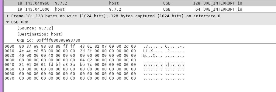
7 years ago The Charging Joy-Con grip seems to have two interfaces with an in/out endpoint per interface for each Joy-Con. I haven't managed to get any replies from input I've sent, however the Joy-Con grip, once an HID session is started, seems to send packets matching the first MAC address handshake command for UART every time the Joy-Con are inserted and ejected. The format seems to go as follows:
81 01 <03 for eject, 00 otherwise> <inserted Joy-Con type, 01 for Left, 02 for right> <MAC>
This can also be observed from Wireshark:
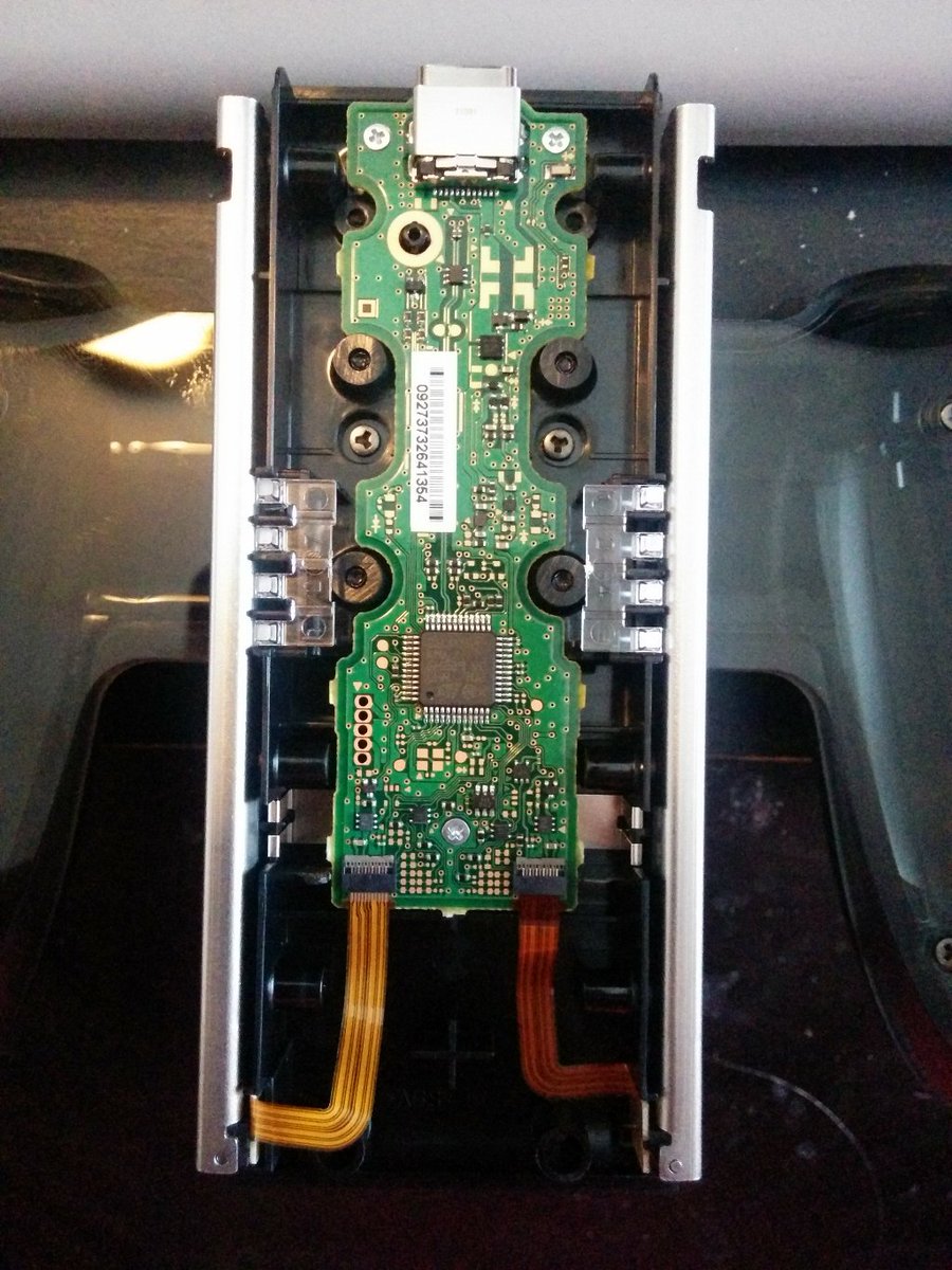
The charging grip also has the same STM32 chip as the pro controller, and the same 5-pin layout found on the dock. Maybe the firmware can be dumped same as the dock to learn more about UART and Bluetooth commands @dekuNukem?
shinyquagsire23
commented
7 years ago Checked out the USB capture from @aspalmer and sending 0x80 0x01 gives me that MAC packet. It seems to respond to some of the other output reports in the capture similarly, so it seems that two Joy-Con in a charging grip effectively functions as a Pro Controller with two interfaces.
 a7a00
commented
7 years ago
a7a00
commented
7 years ago Guys, please see #11; I don't think the HD rumble data is HID compliant.
shinyquagsire23
commented
7 years ago I have the firmware for the Joy-Con charging grip, doing a quick search for A1 A2 A3 A4 gets me a hit so it does seem that they talk to Joy-Con and have some sort of shim to HID. The firmware is pretty small though, 0x10000 bytes total. Willing to bet there's a point where UART and HID have to match up, that or this thing is a dedicated MAC address fetcher but I have my doubts there.
EDIT: For anyone else's curiousity, the 5 througholes are an SWD debug interface, from top to bottom:
??
SWDIO
GND
VDD
SWCLK
I also had to tap the test pad above the middle bottom screw for nRST. Dumping is pretty straightforward with OpenOCD.
EDIT 2: It seems this thing is definitely capable of sending post-handshake UART packets, and most of the handshake is done by the device, though for post-handshake packets the question is how it gets triggered I suppose:

fossephate
commented
7 years ago Has anyone managed to read any gyroscope or accelerometer data over bluetooth? I haven't had any luck so far.
fossephate
commented
7 years ago @riking I figured out what stick_unknown is it appears that the X component of the stick data isn't just nibble reversed, specifically, the second nibble of second byte is combined with the first nibble of the first byte to get the correct X stick value:
uint8_t stick_horizontal = ((stick_data[1] & 0x0F) << 4) | ((stick_data[0] & 0xF0) >> 4);
I don't have any idea what the other nibbles are, they seem random to me, but I haven't looked at them too closely.
shinyquagsire23
commented
7 years ago It seems there is indeed a set of HID commands which allow sending UART commands, ~however they cannot be accessed until handshaking is complete, and I'm not sure of the command to do that (seems to be done elsewhere from the main loop)~.
Commands which seem to exist at 0x0800BB00 are:
80 01 (Handled elsewhere? Returns MAC packet)
80 02 (Do two handshakes 19 01 03 07 00 91 10 00, 19 01 03 0B 00 91 12 04)
80 03 (Do baud switch)
80 04 (Set something to 1)
80 05 (Set something to 0)
80 06 (Something with sending post-handshake command 01 00 00 00 00 00 00 00 01 06 00 00, maybe baud related as well?)
80 91 ... (Send pre-handshake command? Has some weird lookup table stuff)
80 92 ... (Something with pre-handshake commands?)
01 ... (Send post-handshake command? Sends 0x31-large UART starting with 19 01 03 07 00 92 00 00 with checksum edited in and the rest of the HID request pinned on)
10 ... (Same as above)
EDIT: turns out the 'lookup table' stuff for 80 91 is actually for incoming UART data size, just managed to send a raw pre-handshake UART packet like such:
memset(buf, 0x00, 0x100);
buf[0] = 0x80;
buf[1] = 0x91;
buf[2] = 0x01;
buf[3] = 0x0;
buf[4] = 0x0;
buf[5] = 0x0;
buf[6] = 0x0;
hid_write(handle_l, buf, 0x7);
And the resulting data I got back was the MAC packet in a slightly different form:
81 91 00 94 01 08 00 00 3c 68 01 fd bf e8 8a bb 7c 00 00 00 00 00 00 00 00 00 00 00 00 00 00 00 00 00 00 00 00 00 00 00 00 00 00 00 00 00 00 00 00 00 00 00 00 00 00 00 00 00 00 00 00 00 00 00EDIT 2: Seems 80 92 actually works to a degree to send post-handshake commands (with pre-handshake headers?), this works to get something resembling an input packet, but none of the actual input shows up.
memset(buf, 0x00, 0x100);
buf[0] = 0x80;
buf[1] = 0x92;
buf[2] = 0x00;
buf[3] = 0x01;
buf[4] = 0x0;
buf[5] = 0x0;
buf[6] = 0x69;
buf[8] = 0x1F;
hid_exchange(handle_l, buf, 0x9);
EDIT 3: For the record...
Since the firmware tells me this, these are the return sizes for any 19 01 03 07 00 91 XX ... UART command:
01 - 0xF
03, 05, 06, 07, 13, anything else? - 0xB
18 - 0x37
40 - The size specified in the u16 following the XX commandI left my controllers on the grip for a few days and now the status packet[1] is 0x6E on the R, but it's still 0x8E on the L. Battery level?
EDIT: Docked the controller for a bit and it's back to 0x8E. Definitely a single nibble of battery
Also, noticed something weird. The kernel is always returning 0 for the number of actual bytes written :thinking: This may be why I had no response to writes other than 0x1 :thinking:
riking
commented
7 years ago Here's what the Linux Kernel gives for the report descriptor over bluetooth:
https://www.irccloud.com/pastebin/P60ntzyH/
@shinyquagsire23 can you dump /sys/kernel/debug/hid/*/rdesc with the Charging Grip?
shinyquagsire23
commented
7 years ago @riking That file doesn't seem to exist for me, but the charging grip also doesn't function as a controller by default.
Also, I've managed to get a full initialization of the Joy-Con via the charging grip. The charging grip is able to send any UART command, so I am able to pull for full input at around 16ms per input, in addition to being able to dump my Joy-Con SPI firmware over HID. My HID program can be found at my repo, https://github.com/shinyquagsire23/HID-Joy-Con-Whispering
Hopefully with that, it should be possible to test Joy-Con functionality more in-depth. I did try to have the same HID commands sent over Bluetooth but it seems it's not the same protocol, unfortunately...
riking
commented
7 years ago Sorry, the underscores weren't meant to be literal - replace them with the kernel-assigned device identifier.
The file should be there if hidapi can open the device, so sudo ls the directory.
but it seems it's not the same protocol, unfortunately...
Dang :(
shinyquagsire23
commented
7 years ago @riking Ah, I did replace the underscores but I guess I forgot to escape something and it failed, https://gist.github.com/shinyquagsire23/89ea38220e221950a233cd23f2fde28f
riking
commented
7 years ago Okay, wow. Much more straightforward than the Bluetooth dump. Looks like a charging grip is almost all you need to use the joycons as a controller, I'll have to get one and add button mapping support in to my program.
Still doesn't help with the Bluetooth protocol except to reinforce that yes, 0x80 is definitely a bridge to the wires and it's definitely not available over Bluetooth.
ghost
commented
7 years ago Bit of a long shot, but input 33 and 129 look like pitch/yaw inputs of a gyro
riking
commented
7 years ago 33 is the status report (0x21) sent in reply to a 0x1 HID output report and parsed here https://github.com/riking/joycon/blob/master/src/joycon_input.c#L53
fossephate
commented
7 years ago Do we have any way to capture bluetooth traffic between the JoyCons and the switch? Or would we need something like this?: https://www.adafruit.com/product/2269 If I get one I'll be sure to document what I find here
riking
commented
7 years ago It's not BLE, it's standard Bluetooth. Which means you need to pull a full MITM. The hardware for that is in the range of $20,000USD according to
On Thu, Apr 13, 2017, 4:55 AM Matthew Fosse notifications@github.com wrote:
Do we have any way to capture bluetooth traffic between the JoyCons and the switch? Or would we need something like this?: https://www.adafruit.com/product/2269 If I get one I'll be sure to document what I find here
— You are receiving this because you were mentioned. Reply to this email directly, view it on GitHub https://github.com/dekuNukem/Nintendo_Switch_Reverse_Engineering/issues/7#issuecomment-293870587, or mute the thread https://github.com/notifications/unsubscribe-auth/AAmUs3XofGlj-IyuDe2CpsqlWNG5pAWHks5rvg0zgaJpZM4MeLfB .
fossephate
commented
7 years ago I was afraid that might be the case, but wasn't sure, I'll probably pick up a charging grip sometime soon and see if I can find anything.
riking
commented
7 years ago Got a charging grip, but I'm going to continue the Bluetooth research.
Based on the data from the other Joy-Con I just tested with, the battery data is actually just a single nibble - 2 was low according to the console, so probably a 0-8 or 1-8 scale.
fossephate
commented
7 years ago I also just got a charging grip, If I find anything I'll post it sometime soon.
dekuNukem
commented
7 years ago just a reminder guys, feel free to submit a pull request with findings so they'll have more visibility.
 Kekskruemel
commented
7 years ago
Kekskruemel
commented
7 years ago Don't know if this help you guys but matlo, creator of gimx programmed a little bluetooth proxy here is the link https://github.com/matlo/l2cap_proxy greetings
riking
commented
7 years ago Looks like the Switch is rejecting my attempts to connect to it from my computer - guess I need a BT radio that supports MAC spoofing.
Once I get that, I can do the l2cap_proxy and capture the controller data!
fossephate
commented
7 years ago According to https://github.com/matlo/l2cap_proxy, "The master and the device have to be paired with the bluetooth dongle." I wasn't able to get anything to work, either; I also tried a different bluetooth mitm/proxy I found here: https://github.com/conorpp/btproxy. I might get an ubertooth one, and see if I can make any progress with that.
fossephate
commented
7 years ago I've bought an Ubertooth One, and with some scanning I've managed to get the device "Nintendo Switch" to show up with an associated BTADDR, hopefully I'll make some more progress later today when I get the chance, progress might be a bit slow as I familiarize myself with the Ubertooth One. If anyone wants me to run any tests or needs any specific info, just let me know.
Also, can anyone @shinyquagsire23 @riking confirm whether or not the JoyCons w/charging grip or pro controller communicate over USB when connected to the dock (or do they just charge)? They are clearly capable, so I wouldn't be surprised if they do; If they do, it should be relatively easy to sniff/intercept and it could provide some insight on the bluetooth JoyCon <-> Switch communication.
ghost
commented
7 years ago @mfosse Limited understanding of how it works on the Switch side of things, but I wasn't able to get any HID input via USB. Only via Bluetooth.
 finger563
commented
7 years ago
finger563
commented
7 years ago I'm currently trying to write some code to just communicate to a single JoyCon using an L2CAP Bluetooth socket, and can get it to respond to some commands, but the responses seem meaningless to me and I can't get it to send me input data, have you all figured out how to properly get it to send data just over Bluetooth on a BT socket?
 elandyboys92
commented
6 years ago
elandyboys92
commented
6 years ago Hi, im not a programmer, but does anyone here know a way to control the nintendo switch using a pc and a generic controller. Either having the switch recognizing the input as a procontroller or as joycons?
dekuNukem
commented
6 years ago I made a custom board for remotely controlling joycons https://github.com/dekuNukem/joyAnalog
You can take apart a pair of joycons, solder wires on to button test points and connect them to the board. It's a lot of work but before the joycon is completely reverse engineered this is probably the only way. Here s a video: https://www.youtube.com/watch?v=aj1JLARaZQg
elandyboys92
commented
6 years ago Thanks!
On Jun 11, 2017 6:01 PM, "dekuNukem" notifications@github.com wrote:
I made a custom board for remotely controlling joycons https://github.com/dekuNukem/joyAnalog
You can take apart a pair of joycons, solder wires on to button test points and connect them to the board. It's a lot of work but before the joycon is completely reverse engineered this is probably the only way. Here s a video: https://www.youtube.com/watch?v=aj1JLARaZQg
— You are receiving this because you commented. Reply to this email directly, view it on GitHub https://github.com/dekuNukem/Nintendo_Switch_Reverse_Engineering/issues/7#issuecomment-307662843, or mute the thread https://github.com/notifications/unsubscribe-auth/AZpNc4HHdkezbQ6EsOLeyh5w4So9w_dAks5sDHHJgaJpZM4MeLfB .
elandyboys92
commented
6 years ago Ok, so I have no idea how to do that :S Would you sell me one? If I want to play on the switch I need this because I have a special controller (im quadraplegic c6) that allows me to play. I can use my controller with a pc easily and can play on the wii u, xbox and ps4 with workarounds, but cant currently play the switch. I would really apreciate if you could send me one of those circuit boards and maybe some instructions on which points need to be soldered.
Check out my controller if you want :v https://www.youtube.com/watch?v=h9dm2prcSL0
On Sun, Jun 11, 2017 at 6:29 PM, Andrés González elandyboys92@gmail.com wrote:
Thanks!
On Jun 11, 2017 6:01 PM, "dekuNukem" notifications@github.com wrote:
I made a custom board for remotely controlling joycons https://github.com/dekuNukem/joyAnalog
You can take apart a pair of joycons, solder wires on to button test points and connect them to the board. It's a lot of work but before the joycon is completely reverse engineered this is probably the only way. Here s a video: https://www.youtube.com/watch?v=aj1JLARaZQg
— You are receiving this because you commented. Reply to this email directly, view it on GitHub https://github.com/dekuNukem/Nintendo_Switch_Reverse_Engineering/issues/7#issuecomment-307662843, or mute the thread https://github.com/notifications/unsubscribe-auth/AZpNc4HHdkezbQ6EsOLeyh5w4So9w_dAks5sDHHJgaJpZM4MeLfB .
elandyboys92
commented
6 years ago Hi DekuNukem, would you please sell me one of those integrated circuits you made?? I cant play he switch any other way D:
On Mon, Jun 12, 2017 at 11:44 AM, Andrés González elandyboys92@gmail.com wrote:
Ok, so I have no idea how to do that :S Would you sell me one? If I want to play on the switch I need this because I have a special controller (im quadraplegic c6) that allows me to play. I can use my controller with a pc easily and can play on the wii u, xbox and ps4 with workarounds, but cant currently play the switch. I would really apreciate if you could send me one of those circuit boards and maybe some instructions on which points need to be soldered.
Check out my controller if you want :v https://www.youtube.com/ watch?v=h9dm2prcSL0
On Sun, Jun 11, 2017 at 6:29 PM, Andrés González elandyboys92@gmail.com wrote:
Thanks!
On Jun 11, 2017 6:01 PM, "dekuNukem" notifications@github.com wrote:
I made a custom board for remotely controlling joycons https://github.com/dekuNukem/joyAnalog
You can take apart a pair of joycons, solder wires on to button test points and connect them to the board. It's a lot of work but before the joycon is completely reverse engineered this is probably the only way. Here s a video: https://www.youtube.com/watch?v=aj1JLARaZQg
— You are receiving this because you commented. Reply to this email directly, view it on GitHub https://github.com/dekuNukem/Nintendo_Switch_Reverse_Engineering/issues/7#issuecomment-307662843, or mute the thread https://github.com/notifications/unsubscribe-auth/AZpNc4HHdkezbQ6EsOLeyh5w4So9w_dAks5sDHHJgaJpZM4MeLfB .
 AUmrysh
commented
6 years ago
AUmrysh
commented
6 years ago elandsboy92, I would be happy to help you by soldering a pair of joycons. Do you have specs for your controller, an interface or pinout or something?
Kekskruemel
commented
6 years ago I am also interested. Is there any layout for the board ?
 ReconDaemon
commented
6 years ago
ReconDaemon
commented
6 years ago It looks like the following BOM cost, ignoring shipping, would be the price to build 3 of the boards (since the minimum order is 3 PCBs): 3x PCB from OSH Park - $7.15 3x STM32F072C8T6 from Mouser - $9.45 6x ADG714 from Mouser - $29.52 3x AT24C08D (EEPROM) from Mouser - $1.08 6x MBR120 Schottky diode from Mouser - $2.22 3x sot23-5 voltage regulator - $0.36 3x USB Micro-B connectors from Sparkfun - $4.50 (they're currently sold out, might be able to source elsewhere) 6x KMR2 switch from Mouser - $2.10 the other resistors, caps, and jelly beans maybe $10 or something
Considering all of that, the boards are approx $20-$25 each. Might be able to do a group buy to bring the cost down. I'm not sure what resistor and capacitor values you need.
That doesn't take shipping or labor/time into account, which would drive the price up as well. I do think it would be awesome to get elandyboys92 the ability to play the switch with his custom controller :+1:
Hi,
Loving the work you've done - thanks ever so much. Couldn't find you on social media, so am just gonna drop a message here.
Have you been able to sniff the USB or Bluetooth HID protocol it's using? Been trying to bodge a driver together, and don't really have the tools to analyse the protocol. Whilst the buttons and joysticks work fine, I believe the console sends a feature report to the joy-cons to activate gyroscope input. So far I've not had much luck getting the gyroscope and accelerometers to send anything over the standard protocol.
Could be me, or it could be Nintendo's very kind way of introducing security through obscurity. Some help on the matter would be great if you are free.
Thanks