digitaldanny
commented
3 years ago
digitaldanny
commented
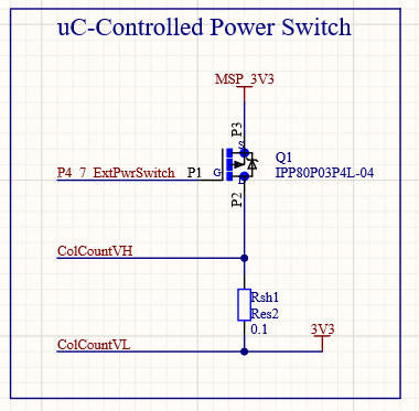
3 years ago It's important to add a current offset to the calculated current draw due to the MSP432 and TPS63020 loads. As shown below, the MSP_3V3 power rail has some additional current that does not go through the shunt resistor. This would affect the battery charge estimation.
The datasheets for both of these devices show the typical current draw for both of these devices. I just need to add these currents to the calculated current draw.
Current MSP432 (VCORE1) - 80 uA / MHz * 16 MHz = 1.28 mA Current TPS63020 - Negligible
MSP_3V3 Rail Current Draw

MSP432 Datasheet - Active Mode Current Draw

This means the current draw conversion in the software will be Vshunt / (0.1 * G_amp) + I_msp + I_tms


Describe the solution you'd like
Additional context
42 - Prototype
26 - Research
OCV and Coulomb Counting circuits below: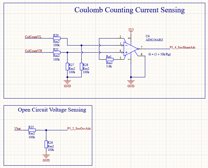
Pch MOSFET Power Switch: