dresco / STM32H7xx

grblHAL driver for STM32H7xx processors
Other
11 stars 12 forks source link

add config for < 20 USD 144 pin STM32H723ZGT6 china breakout board #23

Closed wolfgangr closed 1 month ago

wolfgangr commented 4 months ago

just found this article on aliexpress: https://www.aliexpress.com/item/1005005919904877.html which is more or less a quite bare breakout for a STM32H723ZGT6 i.e. the 144 pin variant of H7 ... loads of pins ... ...would be great to add this as an option .. i'll go to order one an try to get familiar with STM32CubeIDE

maybe, togeether with assistance from You, the the pro's, we get it to work :-)

wolfgangr commented 4 months ago

update: starting dry swiming ... imported github versions to STM32cube and tried to build

unchanged config builds - so the build machine is configured +- OK

playing with my_machine.h:

#error "WeAct Mini STM32H743 supports 3 motors max."
 #error Keypad plugin not supported!

I'm sure, a bare breakout with several dozens of GPIO can support at leas half a dozen of axes, if we connect some driver/level shifters and a huge bread board. How to implement? How to code PIN assignment?

and regarding the keypad, I don't think I'll need it. Have headless setups in mind, with ethernet cables instead of WLAN cables... ;-) Just enabled it to keep stress on the ressource utilisation

some really needed features on my wish list:

Those features are present in the grblHAL ecosystem. How much is the effort to integrate them here?
wolfgangr commented 4 months ago

... switched to board BTT SK 30. (github says, it has just 100 pins in µC, although the type in the schematics is not consistent with ST datasheet) ... and disabled keyboard. warnings regarding trinamic adding up to 14 errors at the end.

disabling TMC stuff getting "MOTOR_FAULT_PIN is not defined!" and "MOTOR_WARNING_PIN is not defined!" .... disabling ....

wolfgangr commented 4 months ago

... disabling plasma ...

/home/.../STM32CubeIDE/workspace_1.14.0/grblHAL Driver STM32H7xx/Debug H743 MiniSTM32H7xx/../Src/weact_mini_h743.c:38: multiple definition of `board_init'; ./Src/btt_skr_3.0.o:/home/.../STM32CubeIDE/workspace_1.14.0/grblHAL Driver STM32H7xx/Debug H743 MiniSTM32H7xx/../Src/btt_skr_3.0.c:38: first defined here
.../STM32CubeIDE/workspace_1.14.0/grblHAL Driver STM32H7xx/Debug H743 MiniSTM32H7xx/../Src/weact_mini_h743.c:38: multiple definition of `board_init'; ./Src/btt_skr_3.0.o:/home/.../STM32CubeIDE/workspace_1.14.0/grblHAL Driver STM32H7xx/Debug H743 MiniSTM32H7xx/../Src/btt_skr_3.0.c:38: first defined here

what's that? weact-baords are commented out! looks like something is quite sticky out there. Is it grblHAL? Or is it the STM32Cube IDE?

dresco commented 4 months ago

would be great to add this as an option

Worth noting (according to reviews) that there appears to be zero information on the board layout - no schematics etc available. So you would need to work out the clock setup, what peripherals are connected to what pins etc.

error "WeAct Mini STM32H743 supports 3 motors max."

error Keypad plugin not supported!

Number of available axis is just dependant on pinout definition in each board map file. Some boards are already configured for 8-axis. The WeAct Mini map is quite basic, as has only been used as a dev board so far..

I've not used or tested the keypad plugin, but no reason it shouldn't work if the necessary (I2C and strobe) pins are defined in the map file.

How to implement? How to code PIN assignment?

Generally you would create a new board definition and a new map file defining the configuration for it. I think for tinkering, you can undefine any of the existing BOARD_XXX definitions, and it will use the generic_map.h file.

plasma THC VFD spindle control TMC 2200 current control ( the ones with UART interfacing)

VFD control, and TMC2209/5160 support is all there and working in the driver. Again, just needs the required pinouts defining in your map file.

I've not looked at the Plasma THC plugin, so couldn't say what the requirements are for that one..

Regarding your compilation errors, may have an easier starting point with the PlatformIO builds?

wolfgangr commented 4 months ago

may have an easier starting point with the PlatformIO builds?

I remember platform I/O some times ago dealing with ESP8266, and it has a steep learning curve, too. I think my error was due to incompatible project configuration in STM32CubeIDE. At least I manage successful builds now.

undefine any of the existing BOARD_XXX definitions, and it will use the generic_map.h file.

done that

create a new board definition and a new map file defining the configuration

tried to clone the btt_octopus, map file, se here https://github.com/wolfgangr/STM32H7xx/blob/master/Inc/my_machine_map.h I' trying now to tinker with settings and look what happens.

Is there anything more to "board definition"? What about those *.json files in ./boards ? Do I need one? How are they evaluated? Can I just make a clone, too? Or continue to use the octopus?

There is a feature in STM32CubeIDE, where the conditional #if preprocessor directives are greyed out when not active. Can I rely on that?

The reason I ask is that independent of Y_AUTO_SQUARE setting, it looks like all board map files only implement 3 axes. I also expect sth like #define N_AXIS 4 should result in different greyed out in the conditional sections of the relevant board_map.h files.

It works this way e.g. with TMC settings.

Am I wrong with that expectation? Or ist the axis number dependency broken? Or haven't I not yet understood it properly?

Is there any other way to check the correct evaluation of the settings?

there appears to be zero information on the board layout

partly agree. Completely agree with regard to the LCD and Camera connectors. But regarding all the GPIO pins, they are labelled in silk on the back of the board, as you can see when you scroll down in the ad. So I hope that's sufficient for most we need. And yes, one cannot read any print on the x-tal in the image. I hope it is better when the board arrives. Is there more to clock rate setting?

dresco commented 4 months ago

I think my error was due to incompatible project configuration in STM32CubeIDE.

Yep, the advantage of the PlatformIO setup is that (almost) all the configuration is in the one platformio.ini file. In CubeIDE, as you probably found, it's a combination of whats buried in the build settings, plus what is defined in my_machine.h.

Is there anything more to "board definition"? What about those *.json files in ./boards ? Do I need one?

You can ignore the /boards folder if not using PlatformIO. That does remind me though, I don't think I set up a CubeIDE build option for the Octopus board when I added it. Presumably you've copied from one of the other H723 (non-bootloader) options instead?

Am I wrong with that expectation? Or ist the axis number dependency broken? Or haven't I not yet understood it properly?

Nope, the greying out should be accurate, and N_AXIS should be all you need to set. Possibly needs to be defined in the project settings instead of my_machine.h, as it's a core GRBL setting?

But regarding all the GPIO pins, they are labelled in silk on the back of the board

I was thinking more of what was already on the board - SPI flash and the SDCard. SDCard is already supported using 4-bit SDIO on the SDMMC1 peripheral. Am planning to add Quad SPI support for Winbond W25Q flash - as this is already used on the WeAct Mini, and on my own board I'm designing. With luck both parts on this board will be wired up the same..

Clock setup will just be down to the crystal speed, will hopefully be 25MHz like all the other Chinese boards.

Cheers, Jon.

wolfgangr commented 3 months ago

ah ... :-\\ - my mistake was to take this line verbatim:

#define BOARD_MY_MACHINE // Add my_machine_map.h before enabling this!

this is a placeholder for just any machine name, and not only this file has to be created, but also some Src/my_machine.c And there are dependencies in Inc/driver.h, in Src/driver.c and in some other files in Src/. grep -nr btt_octo /Src does a good job....

Is there any development guide around for this task, or do I still have to learn it the hard way?

wolfgangr commented 3 months ago

i'll call the board FK723M1-ZGT6, which is printed to silk. Searching the web reveals some PCB design pages refererring right to the front side of this board, but I can't drill down to some schematics or at least a net list.

wolfgangr commented 3 months ago

making progress. Error messages now really are correlated to my new board map: https://github.com/wolfgangr/STM32H7xx/blob/master/Inc/FK723M1-ZGT6_map.h

regarding my wish list (including feature creep):

keypad

postponing this for the moment. get error 'spi_irq' undeclared (first use in this function) driver.c /grblHAL Driver STM32H7xx/Src IRQ issues - looks like a lot of RTFM....

VFD spindle control

Looks good. Had to enable a second uart aka SERIAL1_PORT. Hope the pin management still works...

TMC 2200 current control ( the ones with UART interfacing)

Looks good. had to dig into dependencies in driver.h and ... ouhhh . hope git will know....

MOTOR_FAULT_ENABLE and MOTOR_WARNING_ENABLE

This is for TB660, DM556 and similiar drivers. Throws

Description Resource    Path    Location    Type
'MOTOR_WARNING_PORT' undeclared (first use in this function); did you mean 'MOTOR_WARNING_BIT'? driver.c    /grblHAL Driver STM32H7xx/Src   line 2570   C/C++ Problem
'MOTOR_WARNING_PIN' undeclared (first use in this function); did you mean 'MOTOR_WARNING_BIT'?  driver.c    /grblHAL Driver STM32H7xx/Src   line 2570   C/C++ Problem
'MOTOR_FAULT_PORT' undeclared (first use in this function); did you mean 'MOTOR_FAULT_BIT'? driver.c    /grblHAL Driver STM32H7xx/Src   line 2566   C/C++ Problem
'MOTOR_FAULT_PIN' undeclared (first use in this function); did you mean 'MOTOR_FAULT_BIT'?  driver.c    /grblHAL Driver STM32H7xx/Src   line 2566   C/C++ Problem

So, desperately, doing the pinout is on my ###TODO for finding some free places, which I'm confident will be there

plasma THC

still on my ###TODO

wolfgangr commented 3 months ago

stuck on plasma issue.

Description Resource    Path    Location    Type
undefined reference to `plasma_init'    plugins_init.h  /grblHAL Driver STM32H7xx/grbl  line 33 C/C++ Problem

looks like the sources of ./plasma/thc.c , where plasma_init resides, are not included in the build.

How ist this supposed to be accomplished? Is there something like a central makefile? plasma ist missing e.e. form platformio.ini and from driver.json. Any hint?

================= edit: solved :-)

In CubeIDE, as you probably found, it's a combination of whats buried in the build settings

Thank you for the hint.

manually entered "plasma" in the "project property" | "C.. General" | "Paths and Symbols" | "source location" | "add folder"

and - alas - it builds.

My suspicion from quarter knowledge ist, that in the import process, the Cube might interpret the platform.ini or sth like that.

wolfgangr commented 3 months ago

Nope, the greying out should be accurate, and N_AXIS should be all you need to set. Possibly needs to be defined in the project settings instead of my_machine.h, as it's a core GRBL setting?

Hm.... then still the AXIS-Expansion does not work as expected.

Tried to dig down the way of N_AXES via N_ABC_MOTORS, N_ABC_AXIS from my_machine.h, config.h, motor_poinst.h, drive_opts, nuts_bolts.h, and whatever, down to any [axis]_[STEP|DIRECTION|LIMIT|ENABLE]_[PIN|PORT] in my_machine_map.h.

I'd assume that they are not processed in the right order. Could it be that STM32CubeIDE project definition bites me again? That platform.ini defines the right sequence, but the project importer of STM32CubeIDE breaks this sequence?

If this were true, might I then check/raise issues upstream, where I got pointed to install STM32CubeIDE, as that was here https://github.com/grblHAL/core/wiki/Compiling-GrblHAL#eclipse-based-ide and here? https://github.com/grblHAL/drivers

In dark times long ago, I rember to control the sequence of processing by #include statements. Couldn't this be the 'clean' way to go here?

wolfgangr commented 3 months ago

.... N_AXIS [ ... ] defined in the project settings ...

this improves consistency quite a lot, but still not perfect.

There is an interaction e.g. between [X|Y|Z]_AUTO_SQUARE in my_machine.h and N_AXIS in the project settings, which boil down to the number of motor control output really required in [whatever]_machine_map.h.

When I change the project setting, I get asked to "update index", and then all display is fine. When I change some *_AUTO_SQUARE, the display is not updated any more. After a build, at least the pin-assignment looks ok, and the error checking at the beginning is correctly evaluated in the build. However, the display of the error checker lines still may stay wrong.

Example: enabled Y_AUTO_SQUARE when N_AXIS is 6. No error displayed in *_machine_map.h. Build - throws an error, as correct, since the effective number of axes required is 7, wich exceeds the settings. Even when I comment out the Y_AUTO_SQUARE in my_machines.h, the *_machine_map.h displays unchanged. Only when I change N_AXIS in the project settings, and hit 'rebuild index', it displays correctly.

Essence: quirky, but in a 'works for me' status. I think it suffices to put the chips facility towards its limits (in the schematics of btt octopus, motor pins count up till 10!) and derive a sensful pinout for documentation and testing.

Report upstream?

dresco commented 3 months ago

Is there any development guide around for this task, or do I still have to learn it the hard way?

Hard way I think, sadly. Just by looking at what is done for other boards (and other drivers, F4, F7 etc).

The only reason for the board specific .c files is for a board_init() function. I had originally put the Trinamic initialisation code here, but with hindsight, I think this was a mistake. I plan to move this to the common init code, and remove these files..

i'll call the board FK723M1-ZGT6, which is printed to silk.

If you're producing a carrier board for it, perhaps name it after your own board? Others may also use this dev board as a base for their builds, so I think your pin mappings should be kept separate from the underlying board.

keypad, spi_irq

Have not used or tested this. Have you defined the pins in your map, sounds like perhaps the strobe pin isn't set?

motor fault

I know this is not handled in the F7/H7 drivers yet. I have a motor fault input on my board (for external stepper drivers), and this came up then..

manually entered "plasma" in the "project property

Thanks. I'll have just forgotten to add the latest plugin folders (plasma, embroidery etc) to the CubeIDE build configurations, will do that in my next update.

N_AXIS

I believe this is working as designed, at least is the same in the upstream F7 driver. I think the difference is that it's a core GRBL setting, rather than a driver setting - and not something that can be set in my_machine.h. Suspect your choices are to change it in the grbl submodule (not recommended), or pass it in as a project build setting.

STM32CubeIDE

As you say, just quirky with rebuilding the index.. I think it is what it is!

A couple of other thoughts;

I guess you are aware of the external interrupt limitations with the STM32 parts? i.e. one interrupt per pin number - irrespective of port. So all the external interrupt capable pins need to be on unique pin numbers -- limit switches, controls (cycle start, feed hold, halt), door, probe, spindle index, keypad strobe etc etc. Is quite a pain!

You also mentioned Ethernet. Is that still in your plans? Worth noting that the only Ethernet support in the F7/H7 drivers is using the internal MAC, with external LAN8742 PHY over RMII interface. I'd have a bit of a question mark over successfully running that over the headers..

wolfgangr commented 3 months ago

If you're producing a carrier board for it, perhaps name it after your own board?

nope, that's not the plan. Maybe, the carrier is a breadboard, but due to the double pin rows, it will be du pont cables... If you consider a pull, please tell me a proper name. Otherwise I'l leave it for the moment.

you are aware of the external interrupt limitations with the STM32 parts?

ouh ... not really. My hope was that I had not to dig that deep. But thank you, good to know. So I'll restrict myself from adding too many luxury features. Is it really required for all those contacts with low frequency and loose latency requirements to have an individual interrupt? Cant't they share, or even use polling? Just a silly proposal of a newbie with no clue of grbl internals...

the only Ethernet support in the F7/H7 drivers is using the internal MAC, with external LAN8742 PHY over RMII interface.

oh, good to know. I actually had sth like a wiznet W5500 in my mind. There are no LAN8742 breakouts for sale at aliexpress or ebay, so looks like RMII ist not something to be routed successfully over du-ponts.... Have to rethink....

dresco commented 3 months ago

Otherwise I'l leave it for the moment.

Sure, no problem.

Is it really required for all those contacts with low frequency and loose latency requirements to have an individual interrupt?

Is just the way it's expected in the grblHAL internals. Unfortunately the STM32 limitation is that external interrupts can't be shared between pins. Agree is a bit of a headache, 144 pins and only 16 external interrupts..

I actually had sth like a wiznet W5500 in my mind

Might be worth following this discussion on the F7 driver repo, someone else interested in adding Wiznet support. If it gets added to the upstream F7 driver then I would port across to H7, but I'm trying not to diverge too far.

wolfgangr commented 3 months ago

Might be worth following this discussion

ah, looks good, many thanks for that :-)

I'm still striving with pinout. I see that plasma-thc pins are not explicitly assigned, but selected from an number of auxiliary Ports: (https://github.com/grblHAL/Plugin_plasma/blob/ce41cfc714834bf6476dc734679d78bf1aa0b646/thc.c#L738)

n_ain = ioports_available(Port_Analog, Port_Input);
n_din = ioports_available(Port_Digital, Port_Input);

Looks hard to debug while coding. Is there a way to debug port state in running grbl? Eg list state / voltage at the aux inputs?

Will any input port be set to analog mode anutomagically here: https://github.com/grblHAL/Plugin_plasma/blob/ce41cfc714834bf6476dc734679d78bf1aa0b646/thc.c#L758

plasma.port_arc_voltage = --hal.port.num_analog_in;

Or is there a specific way to declare auxilary analog input? Could not grep that out of the code...

====================

edit:

just found ioports_analog.c with all the assignments of ports and ADC channels there. Can I rely on that, or is it just pulled in from upstream and still work in progress? If so, might MCP3221 the safer way to go?

edit heureka 2: Src/driver.c#L208 ff

#ifdef AUXINTPUT0_ANALOG_PIN
    { .id = Input_Analog_Aux0,    .port = AUXINTPUT0_ANALOG_PORT, .pin = AUXINTPUT0_ANALOG_PIN, .group = PinGroup_AuxInputAnalog },
  ....
dresco commented 3 months ago

Can I rely on that, or is it just pulled in from upstream and still work in progress?

Just pulled from upstream & untested.. It's not a feature I've paid any attention to, so no idea how ready for use it is. You might want to ask the question of Terje in the main repo?

Is there a way to debug port state in running grbl?

Yes, there is the (fairly recent) $PINSTATE command for aux pins.

wolfgangr commented 3 months ago

Worth noting (according to reviews) that there appears to be zero information on the board layout - no schematics etc available. So you would need to work out the clock setup, what peripherals are connected to what pins etc.

Just had a closer look to the WeAct mini. Looks like both boards share the same genes, may be one the clone of the other, or shared ancestry.

I'd prefer the open design of the WeAct. We have a schematic. I don' know how to open the IntLib file there, but I hope that this contains evereything needed to get it manufactured. So no dependency on obscure sources.

The ony disadvantage is that the WeAct mini has "only" 40 GPIO available. In the current map file, it is limited to 3 axes only. May I assume that just nobody tried to take use of all the available ports? So, I might try that. Or is there any deeper limit in the design for that choice?

The other issues (thc & analog ports, W5100) I expect to be unchanged, right?

dresco commented 3 months ago

I'd prefer the open design of the WeAct.

Yes, 100% agree.

May I assume that just nobody tried to take use of all the available ports?

Correct yes, was just set up with 3 axis as a minimum configuration for testing. There is no deeper limit, except some of the pins are also routed to the onboard peripherals. I mapped them all out somewhere, will find and attach it later. If you ignore the camera and lcd connectors, it's really just the SDCard and the two flash chips (one SPI, one Quad SPI). I'll be adding support for the Quad SPI flash when I add the support for my current board design.

I made a simple breakout board when I got my WeAct Mini. Made for easy access to the signals when prototyping with jumper wires (provides two signal and one ground pin for each I/O, plus power & ground sections). Have a few spare boards, so happy to send you one for cost of postage if useful?

image

The other issues (thc & analog ports, W5100) I expect to be unchanged, right?

Correct, yes. I've only got a build for the original H743 board in the repo at the moment, but will be trivial to add the current H723 variant.

dresco commented 3 months ago

Was done a while ago, so no guarantees on the accuracy, but this is what I documented at the time..

WeAct MiniSTM32H7xx default pin assignments & GRBL map.pdf

wolfgangr commented 3 months ago

if ETHERNET_ENABLE

just found in driver.h:

    /**ETH GPIO Configuration
    PC1     ------> ETH_MDC
    PA1     ------> ETH_REF_CLK
    PA2     ------> ETH_MDIO
    PA7     ------> ETH_CRS_DV
    PC4     ------> ETH_RXD0
    PC5     ------> ETH_RXD1
    PB11     ------> ETH_TX_EN
    PB12     ------> ETH_TXD0
    PB13     ------> ETH_TXD1
    */

I hope this is not the pinout W5100. Rember this with a simple SPI connection. 4ports, vdd, gnd ans reset. Otherwise, it would quite screw my pinout plans...

dresco commented 3 months ago

I hope this is not the pinout W5100. Rember this with a simple SPI connection. 4ports, vdd, gnd ans reset. Otherwise, it would quite screw my pinout plans...

No, that's the RMII pinout for the 144pin H7 Nucleo boards

Edit: in fact that's not quite true. For current master that's the pinout for 144pin F7 Nucleo boards, which are a bit different to the H7 Nucleos. (Comments carried across from upstream driver).

wolfgangr commented 3 months ago

oh, good luck. could you point me where to start with W5100 configuration? What port names have to be defined? were it even possible to hare the SPI bus with the trinamic? Or are there conflicts in regard to timing, software or such?

wolfgangr commented 3 months ago

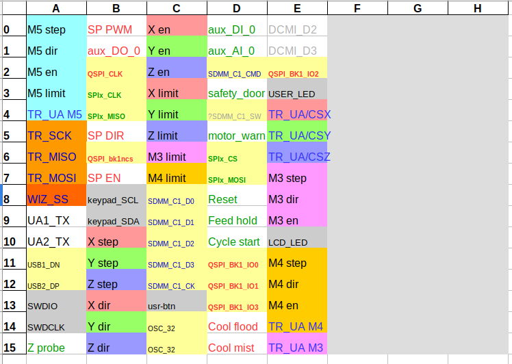
based on your pinout

WeAct MiniSTM32H7xx default pin assignments & GRBL map.pdf

I expanded it quite towards the limits: image

dresco commented 3 months ago

The beauty of a dev board is that you can experiment with jumper wires and change your pinout as needed before committing to a PCB (if that's your final intention)..

Just a couple of things I noticed;

Fwiw, my approach would be to start with the pins that are completely fixed (clock, usb, sdmmc1 etc), then look at inputs that need an external interrupt & ensure they are not sharing pin numbers, then hardware features that can only use certain pins (PWM outputs, ADC inputs etc), and finally slot in all the remaining I/O that can go anywhere..

The MCU datasheet & reference PDFs are your guide here. Also STM32CubeIDE / STM32CubeMX. I often start a new project for the specific MCU, and see what pins the configurator allows the various peripherals to be mapped to.

could you point me where to start with W5100 configuration?

No sorry, afraid I'm not going to be much help there. Never used one, or looked at the code.. and it's not something that's on my to-do list for the immediate future..

Cheers, Jon

wolfgangr commented 3 months ago

Feel like hitting the limits of my capabilitites.... time to extend them? Please feel free to tell me when I overuse your time as my teacher :-)

Nevertheless, many thanks for your input.

I don't think D1 is an ADC input is it?

I have a 250 page pdf written "datasheet" on it, but I'm afraid this is not the whole story, right?

There is a list in ./Src/ioports_analog.c:

static const adc_map_t adc_map[] = {
    { GPIOA,  0, 123, ADC1, ADC_CHANNEL_0 },
           .....

can I rely on that?

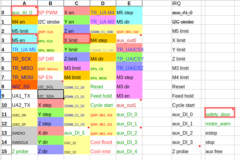
you have multiple interrupt capable inputs on pin 3 (2x limit + door)

hm .... got that.

But how can I find out what inputs need an interrupt? Or does any input?

just found in ./Src/driver.c:

#define DRIVER_IRQMASK (LIMIT_MASK|CONTROL_MASK|DEVICES_IRQ_MASK)

#if DRIVER_IRQMASK != (LIMIT_MASK_SUM+CONTROL_MASK_SUM+DEVICES_IRQ_MASK_SUM)
#error Interrupt enabled input pins must have unique pin numbers!
#endif

This did not hit my when building... hm...

what pins the configurator allows

Is this configurator part of the IDE, or do I have to install another piece, then?

I typed my pins into the _map.h, and got it to build without error. I'm afraid that's not enogh for a working configuration, right?

I believe the keyboard plugin needs an interrupt capable 'strobe' pin in addition to the I2C pins

ok, postponing keyboard for the moment

wolfgangr commented 3 months ago

ah, I see ... the interrupt sanity checking in motor_pins.h relies on N_AXIS setting. When this is 5, M5 ist not checked, although it is used with Y_AUTO_SQUARE enabled.

When I disable Y_AUTO_SQUARE and set N_AXIS to 6, the error message in driver.cL86 bites.

dresco commented 3 months ago

There is a list in ioports_analog.c can I rely on that?

Hmm, it doesn't look like it actually. Has come from the F7 driver, and checking the datasheets shows some differences between the two. (See Table 7. STM32H723 pin and ball descriptions, starting on page 57 of the H723 datasheet). Might also be differences between the H743 & H723 parts. I'll look to fix that this week...

But how can I find out what inputs need an interrupt? Or does any input?

I tried to capture this when I was working on the pinout for my board (based on the IRQMASK code you found above), and I think these are all the possible inputs that require interrupts. Obviously more than 16, and you won't have them all..

X_LIMIT, Y_LIMIT, Z_LIMIT, M3_LIMIT, M4_LIMIT, M5_LIMIT, M6_LIMIT, M7_LIMIT, HALT, FEED_HOLD, CYCLE_START, PROBE (not IRQ yet, but may be in future), PROBE_DISCONNECT, STOP_DISABLE, BLOCK_DELETE, SINGLE_BLOCK, MOTOR_FAULT, MOTOR_WARNING, LIMITS_OVERRIDE, SAFETY_DOOR, MPG_MODE, I2C_STROBE, SPI_IRQ, SPINDLE_INDEX, QEI_A, QEI_B, QEI_SELECT

Is this configurator part of the IDE, or do I have to install another piece, then?

Yep is in STM32CubeIDE, and also available as a separate STM32CubeMX download.

When you create a new STM32 project for a particular part, you get a .ioc file which launches the Pinout & Configuration GUI. Is quite handy as a graphical exploration of the pinouts & available pin mappings for each signal.

Feel like hitting the limits of my capabilitites.... time to extend them?

You're on the right path. I'd just start with a known working breakout board / map, and add one feature at a time. There will doubtless be things that haven't been tested or implemented for this driver yet.. I'll also try to add a build configuration for the H723 version of the WeAct Mini this week.

dresco commented 3 months ago

ah, I see ... the interrupt sanity checking in motor_pins.h relies on N_AXIS setting. When this is 5, M5 ist not checked, although it is used with Y_AUTO_SQUARE enabled.

When I disable Y_AUTO_SQUARE and set N_AXIS to 6, the error message in driver.cL86 bites.

That does sound like a bug to me then, one for @terjeio perhaps?

terjeio commented 3 months ago

That does sound like a bug to me then

Not a bug - testing has to be done with all axes enabled (and other options as well)....

dresco commented 3 months ago

Not a bug - testing has to be done with all axes enabled (and other options as well)....

As far I understand the error description, it's using 6 axis & limit switches either way. With N_AXIS set to 6 the build correctly flags an IRQ conflict on the M5 limit, but with N_AXIS set to 5 & Y_AUTO_SQUARE enabled it doesn't?

wolfgangr commented 3 months ago

Just a couple of things I noticed;

I tried to incorporate your remarks, and this is what it looks like now:

image

Not sure how the Analog input, the Z probe, the unused AUX4 input and the AUX5 intended to be used for THC fits into the IRQ pin conflict picture. My plan is to wait for the board to arrive and give it a live test.

I've keyed this into my ./Inc/weact_mini_h743_map.h and most of it builds - except the last lines defining I2C_STROBE_PORT .

When I uncomment the strobe pin definitions, I get

Description Resource    Path    Location    Type
'spi_irq' undeclared (first use in this function)   driver.c    /grblHAL Driver STM32H7xx/Src   line 434    C/C++ Problem

the whole section around the blamed line is greyes out in the IDE - which I don't understand, since the condition in line 409 is supposed to be true, I think

terjeio commented 3 months ago
Not a bug - testing has to be done with all axes enabled (and other options as well)....

As far I understand the error description, it's using 6 axis & limit switches either way. With N_AXIS set to 6 the build correctly flags an IRQ conflict on the M5 limit, but with N_AXIS set to 5 & Y_AUTO_SQUARE enabled it doesn't?

Ok, my bad. there is a "bug" in the preprocessor code. One has to introduce one to root it out...

dresco commented 3 months ago

and most of it builds - except the last lines defining I2C_STROBE_PORT

Thanks I'll check that. I haven't used the keypad plugin myself, so may well have missed something..

dresco commented 3 months ago

Hi @wolfgangr

For info, have just committed some updates, including adding support for the H723 variant of the WeAct Mini.

Can confirm the build error when KEYPAD_ENABLE=1. However this also happens in the upstream F7 driver, so that'll be one for another day..