 devyte
commented
4 years ago
devyte
commented
4 years ago CC @Tech-TX
Closed petrilloa closed 5 years ago
devyte
commented
4 years ago CC @Tech-TX
 Tech-TX
commented
4 years ago
Tech-TX
commented
4 years ago The only problem though is that it always wakes up with WiFi enabled (RF_CAL option) and I need it to be able to exit deep sleep without WiFi also. t seems to ignore any previous calls to system_deep_sleep_set_option(RF_DISABLED); Could you please provide some insight on which register may control fr calibration at wake up? or at least point to the register reference you used? I can't decipher this function since I wasn't able to find any detailed register map for this address range.
@hpflatorre Henrique, try this: https://github.com/esp8266/Arduino/issues/6642#issuecomment-578462867 The second cut is solid, and I'm hoping I can get it even better. It stops the boot RFCAL and turns the modem off as soon as possible.
Tech-TX
commented
4 years ago By the way, I suspect (but can't verify) that you folks looking at the RESET pulse are on the wrong path. When the voltage at the EXT-RSTB pin on the chip starts to go high, the CPU has already responded to the RESET and has released the driver on GPIO16 (it's changed over from a CMOS totem-pole output to HI-Z input). There's little information on the guts of the chip itself, but the OTHER pins on the chip aren't cleared by reset, they're only reset to inputs if the SDK thinks it needs to init them (power-on or ???). On other CPUs I've used that's a hardware function in the chip's reset state machine, but on the ESP8266 it's driven by software.
 The comment in cyan is mine.
The RTC hardware could be tied into the internal RESET logic (clearing GPIO16 output driver in hardware) but I think it's more likely done in the boot code in the ResetHandler. Not long after that it's loading the SDK from flash, and it appears that's where your execution is going astray since you get the initial boot message. A funky off-brand flash chip would explain your problems more easily than someone cloning the ESP8266, especially if you're not getting the "load 0x4010f000" message which I think comes from the SDK and not the boot ROM. I could easily be wrong on that point as I haven't researched the boot process yet.
The note at the Espressif BBS about the reset duration is very old, and possibly a worst-case even so after power-up.
 omue999
commented
4 years ago
omue999
commented
4 years ago I have the same problem with new ESP-12F. When I pull the MISO pin up to a resistor (47k), the modules run after deep sleep ;-)
 gismofx
commented
4 years ago
gismofx
commented
4 years ago Is this resolved?
I had the same problem and wake was not working after deepSleep on a D1 Mini Clone board.
I noticed that after uploading the board would do it's thing and sleep and then not wake. If I unplugged the board and plugged it back in, it would start working an d waking from deep sleep. My issue was related to using Serial or connected to the serial.
I've yet to try, but Serial1 might be a work-around.
Otherwise, don't use Serial when using deepSleep.
 kebwi
commented
4 years ago
kebwi
commented
4 years ago I'm also having this problem. I have two D1 minis, both clones, but different manufacturers (different logos on the shields). And one is missing the three-legged component between the USB port and the reset switch on the bottom side. At any rate, they both behave exactly the same way. Deep sleep wakens in a garbled (what has been called zombie) state. Two presses to reset fixes it. If I tie D0 directly to RST, then a single press to reset suffices to reboot properly.
I haven't tried the firmware change to the deep_sleep function recommended above because I'm using MicroPython. I may delve into figuring out how to edit the deep_sleep implementation in MicroPython, but I can't believe I'm the first person contending with this problem: MicroPython not deep sleeping properly on the D1 mini. While the Arduino solution above is useful in that environment, I need a MicroPython solution. I'm inquiring on the MicroPython forums about this issue, but I'm dropping it in here too. Has anyone else fixed this in a MicroPython environment already?
Thanks.
kebwi
commented
4 years ago I don't have a 47K lying around, but I tried a 10K on MISO (pin D6) and it didn't fix the zombie wakeup problem. The closet I've come is discovering that directly tying D0 to RST enables me to reboot with a single press to the reset switch, whereas with no connections, it takes two resets, as others have noted above. I don't know what to do. I don't want to buy any D1s, clone or original, or even buy bare ESP-12 boards of any model, until I figure this thing out.
 kpot
commented
4 years ago
kpot
commented
4 years ago TLDR: I've solved this issue for myself. It was caused by a bad power source.
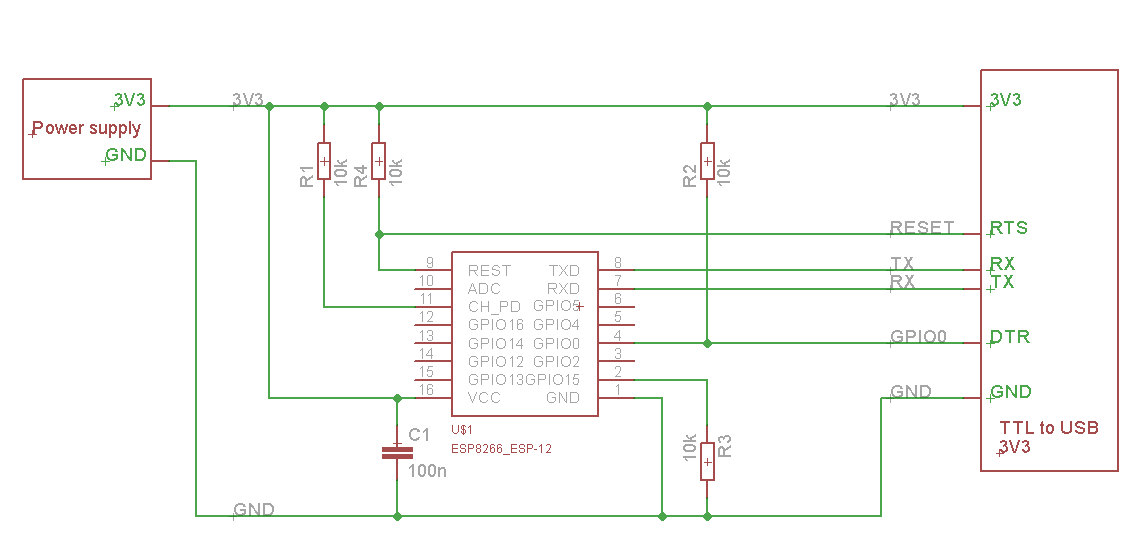
Long version: I've had similar issues with my generic ESP-12F modules from Aliexpress. The same code that had worked perfectly on a bit older ESP07 would hang after 3-15 cycles of deep sleep on ESP12Fs. I don't use any ESP-based boards like Wemos D1. My setup is minimal: just the module, a few resistors, and a USB-serial converter like it is shown on this circuit. GPIO16 was connected to the reset pin through a schottky diode. The whole thing was powered from a good Li-Ion battery through a 1.5A-capable buck (step-down) converter. I had also installed 10uF + 0.1uF capacitors across the power pins of ESP12F, as suggested by official guides from Espressif. So everything was looking good. But still didn't work properly.
After 2 days spent trying various hacks, including the function nk_deep_sleep provided by @nikolz0, I decided to connect my bench power supply (DPS5005) to the board. And just like that, the issue was gone. Then I remembered that my well-working ESP07-based device with the same code was actually powered through an LDO linear regulator, and not through a buck converter.
My best theory is that my buck converter module, although powerful enough, has very bad response time characteristic and is unable to cope reliably with power spikes occurring when ESP12F wakes up and tries to access WiFi, store WiFi settings in flash memory and so on. All these power surges lead to significant voltage drops (suddenly, from few uA in deep sleep to about 80mA), which the buck converter is sometimes too slow to compensate for (bad design perhaps). It may even be oscillating for a bit, trying to stabilize its output. Various ESP modules might have different tolerance for such power deviations, depending on which Flash memory module is installed.
So try different power sources if you have this issue, no matter how confident you are that your current power supply is good enough for the job. If you don't have a lab power supply, try a combination of batteries + an LDO linear regulator (>200mA to have some reserve). This will give you a strong enough low-noise power source that will be helpful in testing your device.
kpot
commented
4 years ago I decided to get to the bottom of this and began tinkering with the power source. I noticed that ESP12F starts freezing after deep sleep every time I set the power supply to provide even a tiny bit below 3.31V. Even 3.29V and ESP already becomes unstable.
Then I connected oscilloscope directly to ESP12F's VCC and GND pins, set the power supply to 3.3 and began to wait. Turned out that every time the module wakes up, the VCC-GND voltage drops in multiple spikes from 3.3V to as low as 3.1V. But every once in a while the voltage spikes down to 3.0-3.05V (a particularly heavy WiFi exchange?), and this is exactly when ESP12F freezes.
I don't know the exact model of flash memory under the metallic shield of the module. If it is something like W25Q32FV from Winbond, it should tolerate voltages down to 2.7V. But I suspect either some ESP12Fs come with cheaper flash memory installed, or the copper traces within the module itself are so thin that the actual voltage provided to the ICs drops inside even further to somewhere below 2.7V.
I've replaced the feedback divider on my previously mentioned buck converter so it would output 3.37V instead of 3.3V and it works perfectly well now.
 genotix
commented
4 years ago
genotix
commented
4 years ago I decided to get to the bottom of this and began tinkering with the power source. I noticed that ESP12F starts freezing after deep sleep every time I set the power supply to provide even a tiny bit below 3.31V. Even 3.29V and ESP already becomes unstable.
Then I connected oscilloscope directly to ESP12F's VCC and GND pins, set the power supply to 3.3 and began to wait. Turned out that every time the module wakes up, the VCC-GND voltage drops in multiple spikes from 3.3V to as low as 3.1V. But every once in a while the voltage spikes down to 3.0-3.05V (a particularly heavy WiFi exchange?), and this is exactly when ESP12F freezes.
I don't know the exact model of flash memory under the metallic shield of the module. If it is something like W25Q32FV from Winbond, it should tolerate voltages down to 2.7V. But I suspect either some ESP12Fs come with cheaper flash memory installed, or the copper traces within the module itself are so thin that the actual voltage provided to the ICs drops inside even further to somewhere below 2.7V.
I've replaced the feedback divider on my previously mentioned buck converter so it would output 3.37V instead of 3.3V and it works perfectly well now.
Great work figuring this out!!
What happens when you place a large capacitor over the buck converter output side to compensate the voltage drop?
kpot
commented
4 years ago Adding capacitors straight across VCC and GND pins of the module does not help. In addition to soldered earlier 10uF + 100nF caps, I tried adding low-ESR ceramic capacitors (47uF and 68uF), beefy 220uF tantalum, low ESR 1000uF electrolytic and all of them combined. They do help to dampen the voltage spikes at the input. However, when I lower the voltage to 3.29V at the next waking everything freezes up again and my terminal shows me the same "sign of death"
ets Jan  8 2013,rst cause:5, boot mode:(3,6)

ets_main.c
So whatever causes the issue, it's inside the ESP12F module. At this point I can only speculate what it could be. Cutting the costs, the manufacturer could entirely skip on installing bypass capacitors across the ICs. Or these capacitors have low quality and high ESR. Or the board itself uses cheap thin copper layers and poorly designed. That's why modules from some batches/manufacturers work well, while some others fail even at their nominal voltage. Awakening from a deep sleep is probably the most stressful conditions we can put the module in. When everything is up and running suddenly and is trying to calibrate, transmit, output, measure, etc.
 mhightower83
commented
4 years ago
mhightower83
commented
4 years ago IMO an important parameter to look at in your switching type power supply is Transient Load response. The ESP8266 can go from sipping 60ma to gulping 300ma in an instant. That is a 400% load increase.
For the 5V power supply circuit paired with an LDO that I looked at, it was a little difficult to capture the dip on the oscilloscope. I had to use AC coupling on the trigger line. Adding capacitors helps with the spikes but did not make up for the slow response from the power supply, which resulted in a short voltage droop. Note adding excessively large CAPs may make the power-on rise time too slow for a proper power-up reset inside the ESP8266. I have read blog comments that leaving an ESP8266 in a failed reset state can be destructive.
I would not expect an inexpensive buck converter to have the load response needed and that operating the ESP8266 at a lower voltage level as you describe may result in Undervoltage during Transient Load.
It might be worth noting, that many of the IoT devices I have looked at, use a switching power supply designed for changing batters. Battery charging doesn't need a good transient load response; however, they pair it with a good LDO voltage regulator to power the ESP8266.
So far I have not seen a retail device that powers the ESP8266 directly from a switching type power supply. They may be out there. I think when the ESP8266 is a part of a device that uses several times more power than the ESP8266 peak, then the Transient Load based on the total power consumed would be much easier for a switching power supply to handle.
Edited: for clarity and corrected load increase calculation.
 Maker39
commented
4 years ago
Maker39
commented
4 years ago Hi guys. I also had problems ESP-01S on which stood flash FT25H08. I tried everything that is written in this thread - nothing helped. Replaced with Winbond 25Q80BVIG and 25Q32BVSIG and now deep sleep and waking up work fine.
 shivan
commented
4 years ago
shivan
commented
4 years ago @kpot so can you suggest a good power module (for 3,7V LiPo battery with charging port) and/or good ESP board?
I currently use the AZ-Delivery ESP8266 (Wemos D1) and Battery Shield 1.2.0 from ILS. Funny is that two independet ESPs with different sketches did not wake up anymore on the same day. Currently I have one here which does not wake up yet.
Can I do further analysis when plugging in to USB-Port? I did not press reset yet, as I still hope to find a way for further analysis.
kpot
commented
4 years ago @shivan Sorry, can't give you any useful advice on which board to pick up, since I haven't found one completely reliable myself. Which isn't a big surprise since most Chinese manufacturers tend to stick with the same (sometimes poor) choice of cheapest components they could find for the job. And there are plenty of knockoffs on the IC market.
USB port usually provides 5V, and (assuming this port is of a good quality and can provide enough current) your bottleneck will be the device converting these 5V down to 3.3V to power your ESP board + its output capacitor. Usually you can find a linear regulator doing the job, like AMS1117 and a ceramic/electrolytic capacitor on its output. These are the ones you'll need to blame if you plug the board in USB port and it still refuses to wake up properly. Either the regulator cannot provide enough current, or the capacitor is too small for the job.
 nikolz0
commented
4 years ago
nikolz0
commented
4 years ago I have already explained that the problem of getting out of sleep is related to the automatic mode selection scheme, which is the same on all NODEMCU and WEMOS boards . The problem is solved simply-use the ESP12 module, the USB adapter, two buttons-reset and mode selection and four resistors, or change the circuit.
kpot
commented
4 years ago I have already explained that the problem of getting out of sleep is related to the automatic mode selection scheme, which is the same on all NODEMCU and WEMOS boards .
If you're saying this is merely a software problem, then I have to disagree. Yes, writing the code differently can sometimes be helpful. It did work for you and some other people, but didn't help in my case (I've tried your solution).
To me the obvious reason why the purely software solution can sometimes work is because it can slightly dampen the wake-up power surges, which in some cases is all that was needed to avoid dangerously low voltage dips. But this just wasn't enough in my case. For me, a better power source did solve the issue without any change in the code.
Maker39
commented
4 years ago When the ESP comes out of sleep , it accidentally switches to programming mode. As a result, the program is not executed. If you remove the automatic mode control scheme, the cause of the problem will disappear. To avoid this problem, you must disable the possibility of a random pulse on the pin GPIO0 at the moment when the pulse appears at the pin RST.
But how then to explain the problem of zombie mode on the ESP-01S modules without a programming mode switch , and powered by a laboratory power supply? And how i have working deep sleep for half a year from Li-po through the WEMOS Battery Shield v 1.2 my WEMOS D1 Mini Pro ? Maybe it makes sense to collect statistics on Flash chips in buggy modules (I think the thing is all the problem) My two ESP-01S had FT25H08 and "zombie mode" problem, but after replase IC FLASH to Winbond it's work fine.
Maker39
commented
4 years ago I probably pointed it out incorrectly. The bottom line is that I use wifi-iot.com firmware on SDK 1.3.0 but not Arduino. So there are no complaints about the software on the SDK. My ESP-01S were equipped by me with a GPIO16-RESET jumper. I tried all the options that helped people in this thread. Nothing helped for me. Only the FLASH replacement helped.
shivan
commented
4 years ago you must disable the possibility of a random pulse on the pin GPIO0
@nikolz0 ok I have a DHT22 at GPIO0 and GPIO2, so it could help, when I put it somewhere else? I'll try that.
Currently I use: GPIO2 = Data GPIO0 = VCC (+)
 leofds
commented
3 years ago
leofds
commented
3 years ago I have the same problem. Pull up resistor (47k or 10k) on the MISO pin, only this worked for me.
 studioant
commented
3 years ago
studioant
commented
3 years ago @nikolz0 - Your deep_sleep code works to sleep and wake the D1, but it draws 2mA while sleeping with your code. The ESP.deep_sleep function (as I measure) draws ~100uA. Is your code more of a 'light sleep' ? Could you comment your code? Let us know what each line is doing please? I understand you're manipulating a register in some sequence?
studioant
commented
3 years ago @nikolz0 I refer to current consumption during sleep mode, specifically, the sleep mode function you have created. I measure it at a constant 2mA. But with Andreas Spiess (in this video: https://www.youtube.com/watch?v=rfPwOtoGO4E ) mod of cutting the 3V3 trace powering the onboard LDO and UART, current during ESP.deepSleep is measured at around 25uA. My question to you is this, what more is required within your function to get the current consumption down this low for these knock off boards?
 inter-coder
commented
3 years ago
inter-coder
commented
3 years ago Here is a trick that solved my problem. On the D1 mini-board, I pull up pins D3 and D4 with 220k resistors and now it wakes up without any problems from a deep sleep
 fsommer1968
commented
3 years ago
fsommer1968
commented
3 years ago Here is a trick that solved my problem. On the D1 mini-board, I pull up pins D3 and D4 with 220k resistors and now it wakes up without any problems from a deep sleep
According to the schematics original Wemo1 D1 mini already have pull up resistors on D3 and D4 (12K). Therefore a correct populated board provided the effective resistance would be 11,38K instead of 12K.
 kghxkgh
commented
3 years ago
kghxkgh
commented
3 years ago Thanks @leofds, I have battled with this issue for months on and off. Was finally able to get the Lolin Nodemcu v3 to wake up from deepsleep using a 220resistor between SD0(MISO) and 3.3v. (this is in addition to the bridging of GPIO16 and RST of course)
leofds
commented
3 years ago Thanks @leofds, I have battled with this issue for months on and off. Was finally able to get the Lolin Nodemcu v3 to wake up from deepsleep using a 220resistor between SD0(MISO) and 3.3v. (this is in addition to the bridging of GPIO16 and RST of course)
I recently discovered a new problem. With the resistor it wakes up, but in my case the boot is slower and once it didn't start the application.
The supplier said it was a bad batch, in the new batch the problem does not occur.
 gordoasan
commented
3 years ago
gordoasan
commented
3 years ago Thanks @leofds, I have battled with this issue for months on and off. Was finally able to get the Lolin Nodemcu v3 to wake up from deepsleep using a 220resistor between SD0(MISO) and 3.3v. (this is in addition to the bridging of GPIO16 and RST of course)
This worked great for me, thank you so much
 manj9501
commented
3 years ago
manj9501
commented
3 years ago I'm having the same issue, with my esp12f modules with 'esp8266mod' written on the shielding. The deep sleep-wake cycle works for number of times initially, but then the esp wakes up but is unable to connect to the WiFi. I tried using 47uf electrolytic caps between Vout and GND and Vin and GND but that didn't help. I'm using MCP1700. I was trying to emulate this project( https://www.instructables.com/Solar-Powered-WiFi-Weather-Station-V20/ ), but my plans have been jeopardized because 2 of my modules are displaying the same anomalous behavior. Any help would be appreciated!
 javiercuellar73
commented
3 years ago
javiercuellar73
commented
3 years ago Just buy another ESP12...
El sáb., 24 de abr. de 2021 08:58, MS @.***> escribió:
I'm having the same issue, with my esp12f modules with 'esp8266mod' written on the shielding. The deep sleep-wake cycle works for number of times initially, but then the esp wakes up but is unable to connect to the WiFi. I tried using 47uf electrolytic caps between Vout and GND and Vin and GND but that didn't help. I'm using MCP1700. I was trying to emulate this project( https://www.instructables.com/Solar-Powered-WiFi-Weather-Station-V20/ ), but my plans have been jeopardized because 2 of my modules are displaying the same anomalous behavior. Any help would be appreciated!
— You are receiving this because you commented. Reply to this email directly, view it on GitHub https://github.com/esp8266/Arduino/issues/6007#issuecomment-826089257, or unsubscribe https://github.com/notifications/unsubscribe-auth/AFZBFG7EQPKN4VRGS4Y6J5LTKK6ANANCNFSM4HHT54AA .
 Anze-
commented
3 years ago
Anze-
commented
3 years ago For me the solution was to force the boot state using proper external pull-ups on pins D3 and D4, and a pull down on pin D8. I used a resistor value around 5kOhm. Then connecting D0 to RST gives proper deep sleep wake in my Nodemcu 12 dev board
 Craig1516
commented
3 years ago
Craig1516
commented
3 years ago The "limbo" state for the ESP8266 & ESP32's is addressed in Andreas Spice's video #315. The main solution he discussed is to use a voltage protection chip. Early in his video he shows another solution that uses a RC circuit on the CHPD/EN pin. The effect is to delay the rise of the CHPD/EN voltage until the rest of the chip is powered and thus avoiding the limbo state. I have not tried that but tried many of the above suggestions to no effect.
[Edit] While attempting to test the RC circuit, I built a protoboard of the PCB where I was experiencing this double reset problem (first reset causes limbo state, second reset chip works fine). The new protoboard has a different ESP-12 because these chips don't easily unsolder. So, new ESP12 on a new protoboard with the identical program ... it works on every reset, not every other reset. Go figure.
[2nd Edit] I did attach the RC circuit to the CHPD/EN pin (47K resistor to 3.3V, 22 uF cap to GND) to the original failed circuit. It didn't work. I do not have an osilloscope so I am flying blind. Hope this helps others.
 msami-shaaban
commented
2 years ago
msami-shaaban
commented
2 years ago @studioant I tested @nikolz0 deepsleep from here at 33 uA which is amazing, only issue is I can't get it to deepsleep past 46 minutes. tested multiple times, doesn't get past a consistent 2800 seconds max sleep.
edit: just had to change "void DeepSleepNK(uint32 t_us)" to "void DeepSleepNK(uint64 t_us)", sorry noob here.
studioant
commented
2 years ago @micanki yep, nice one.
 davidanbernal
commented
2 years ago
davidanbernal
commented
2 years ago Hello, i replace jumper by a resistor of 470 ohm between RST and D0/GPIO16, this work for me.
Tech-TX
commented
2 years ago I think I finally have an explanation (but not a fix) for Deep Sleep Zombie mode.
When you enter Deep Sleep from the SDK or encapsulated Arduino command, the SDK shuts down WiFi and does some assorted housekeeping. Next it loads the remaining entry to Deep Sleep from icache, then puts the Flash chip into "Deep Power Down" mode with a B9h write to the Flash. Then the icache routine finishes stopping the clock PLL and the chip sleeps.
When it wakes, either from the timeout off the RTC section or from external Reset, the clock PLL starts up (around 5ms) and then the boot ROM begins executing, trying to figure out whether to do a cold boot (external Reset) or a soft (Deep Sleep) reset. Then it prints the boot status message (ets Jan 8 2013,rst cause:2, boot mode:(3,6)) and sends a "Resume from Power Down" command ABh to wake the Flash up, and begins executing from the Flash. This is the crucial point that doesn't happen with XTX Flash: they don't wake up, so execution halts. On power-up the Flash is always in ACTIVE mode, but after Deep Power Down only the Resume from Power Down can wake Sleeping Beauty, and XTX chips don't recognize it.
The reason Nikolz0's test code works is because it's avoiding the SDK command that puts the Flash in Deep Power Down, so the Flash is always consuming at least Standby current and possibly up to normal Active current. The Flash isn't asleep when the code begins executing again after Deep Sleep.
My proof for this Zombie hypothesis is that several people mentioned that current consumption was higher with Nikolz0's code than with a typical Deep Sleep. Espressif specs the ESP8266 at 20uA substrate current in Deep Sleep @ 3.3V, and I've measured it at 16uA at 3.0V. If the Flash is in Deep Power Down it consumes another 1 to 5uA; in Standby it consumes 10 to 50uA, and in Active mode it consumes milliamps.
The only way I could measure 16uA Deep Sleep current for ESP + Flash is if the Flash is in the lowest-power mode, otherwise I'd have read 27-67uA if the Flash was in Standby.
Fixing the boot ROM to work with the undoubtedly faulty XTX chips is impossible: it's a mask ROM. Nikolz0's solution will help, but the system will still be consuming between 30uA to milliamps in Sleep, which isn't worthwhile. There's no one simple fix for broken XTX Flash that won't also affect all of the other Flash chips used, increasing power consumption for everyone. The only solution is to return boards with XTX chips to the vendor you bought them from and buy somewhere else. Sorry, there's no easy fix for bad Flash. You can replace it yourself (a few people have), but it's roughly as expensive as throwing bad D1 Mini boards in the trash and buying more.
The way to know whether you've been bit by cheap Chinese Flash is to run this after initializing your serial port: Serial.println(ESP.getFlashChipId(),HEX); The XTX chips will return 0B in the last byte, like this: 16400B
nikolz0
commented
2 years ago Hi, there is a simple and very effective way to control the Deep-sleep mode ESP.
For this method, it is necessary to use the TPL5110 chip – a power management timer,with a consumption current of 35 nA.
The time interval of the timer is set with an accuracy of about 1% using an external resistor in the range from 100 ms to 2 hours.
Connect the control signal from this timer to Chip_EN. As a result, it is possible to obtain a consumption current 5uA in the DeepSleep mode.
However, in this case, it is not possible to use the RTC memory to store parameters. The parameters must be stored in flash.
nikolz0
commented
2 years ago If you are interested in ways to save ESP energy consumption , then read my articles:
Tech-TX
commented
2 years ago Hi, Nikolz0! I wanted to thank you, and assure you that there is nothing wrong with the Deep Sleep test code you provided. It will help people with bad Flash chips to use their modules. They won't get the lowest power Deep Sleep current that we will, but it's cheaper if they don't or can't replace their boards.
For anyone interested, here are some example ESP-12 modules that may contain XTX Flash chips: https://imgur.com/a/8BU70ZW Note that the bad ESP-12 modules that people have described in these threads with Zombie issues have false or illegal copies of the Espressif logo on the RF shield. There is no VENDOR name. They also have the FCC logo, but without the required FCC ID number. You can show the FCC ID number without the logo, but you cannot have the logo without the ID number. That is three different reasons to avoid these counterfeit boards. Here's an example of the XTX logo, if you can see the Flash clearly: https://i.imgur.com/VMNmD07.jpg
I agree that for minimum power you need a separate power supervisor. However, many people here don't have the experience to design their own ultra low power solution, so they use boards purchased from Aliexpress, eBay, Amazon, etc. They are stuck with whatever power control is available on their board.
nikolz0
commented
2 years ago Hi, I checked the deep-sleep ESP-12f mode with my program. The current consumption in DeepSleep mode is 20 uA. I believe that your hypothesis about the error in the ROM is not correct.
 Colkerr
commented
8 months ago
Colkerr
commented
8 months ago The faulty ESP12Fs are still being sold. I've had about 30 - my most recent 3 batches from different Aliexpress suppliers. Exactly this problem although my flash chip ID does not end in 0B. The one I just checked is 162085.
 Sanc0Pansa
commented
7 months ago
Sanc0Pansa
commented
7 months ago I bought 5 pieces of ESP12F in January 2024 on Aliexpress. All 5 pieces had broken Deep Sleep. PullUp 10k to MISO worked on all pieces. Thanks for sharing the solutions.
Sanc0Pansa
commented
7 months ago If someone noticed that I only have 7 pins on the socket, it is not an illusion. I'm using standard 2.54 leaving out 1 pin on each side, GPIO16 and GPIO0. This is my solution from 2mm to 2.54mm pin header.
Colkerr
commented
7 months ago @Sanc0Pansa Thanks for mentioning this. I just tried with one of mine and it worked ! Also just noticed your neat solution to the GPIO spacing on the dev board. Great idea ! I've not seen that suggested before.
Craig1516
commented
7 months ago I haven't worked with the ESP for some time... and haven't studied the history of this thread. But isn't GPIO 16 the WAKE pin? Doesn't that need to be connected to the circuit?
Sanc0Pansa
commented
7 months ago If you look closely at the photo, you can see the GPIO16-RESET bridge.
Craig1516
commented
7 months ago @ Scan0Pansa Yes, sorry to be so careless and thank you for the earlier photos. Funny that I missed that as I have soldered many an ESP-01s with bridges to GPIO16 for the purpose of sleep resets. Apologies!
 vrxiaojie
commented
7 months ago
vrxiaojie
commented
7 months ago Thanks @leofds, I have battled with this issue for months on and off. Was finally able to get the Lolin Nodemcu v3 to wake up from deepsleep using a 220resistor between SD0(MISO) and 3.3v. (this is in addition to the bridging of GPIO16 and RST of course)
OMG Thank you ! I've been finding a solution about this problem for a week.
Colkerr
commented
7 months ago @wjj0227 I have been using 10k. 220 seems very low. I found the exact value isn't necessary. Up to 50k has also worked.
 tstmrtamir
commented
6 months ago
tstmrtamir
commented
6 months ago @leofds Thanks a lot man. I have been struggling with this issue for a week and almost gave up. But this solution is working great. 10k resistor between SD0(MISO) and 3.3v. thanks again
Basic Infos
Platform
Settings in IDE
Problem Description
A few months ago, we start developing a custom PCB using ESP8266, ESP12F from AI.
esptool.py --port COM14 flash_id esptool.py v2.6 Serial port COM14 Connecting... Detecting chip type... ESP8266 Chip is ESP8266EX Features: WiFi MAC: cc:50:e3:04:37:7e Uploading stub... Running stub... Stub running... Manufacturer: 20 Device: 4016 Detected flash size: 4MB Hard resetting via RTS pin...
After successfully deploy 100 boards, we receive a new batch from a distributor on China. The new chip, looks the same as the old one, except it has an Expressif logo instead of AI logo.
Then, using esptool, we check that was manufactured by other factory
esptool.py --port COM14 flash_id esptool.py v2.6 Serial port COM14 Connecting... Detecting chip type... ESP8266 Chip is ESP8266EX Features: WiFi MAC: dc:4f:22:5e:93:23 Uploading stub... Running stub... Stub running... Manufacturer: 0e Device: 4016 Detected flash size: 4MB Hard resetting via RTS pin...
The PCB was build using all the following design rules and experiences from Espressif, blogs, etc. Example: https://www.instructables.com/id/ESP-12F-ESP8266-Module-Minimal-Breadboard-for-Flas/
Also, we using several recomendations from videos of Andreas Spiess. @SensorsIOT and read post by @igrr.
Power: 3 x AA Batteries (4,5v)
MCP1700 LDO for 3,3v
Capacitor filters: 1000uF and .1uf - VCC to GND
GPIO0 - pull up 10k resistor - VCC
GPIO2 - pull up 10k resistor - VCC
GPIO15 - pull down 10k resistor - GND
EN - pull up 10k resistor - VCC
RESET - pull up 10k resistor - VCC
HARD WIRED GPIO16 to RESET pin.
The sensor, reads a value, then enter a deepSleep cycle until wakeups. All was working fine in more than 100 pcb!!!
After receiving the new batch, with the same PCB and CODE, the ESP hangs after wake up.
We already try 10 chips off the new bach, all have the same issue.
Trying this simple sketch:
MCVE Sketch
Debug Messages ON WORKING CHIP
Debug Messages ON NOT WORKING CHIP
Hangs/Freeze until power down, or hard reset (button from RESET to GND).
Things we already try
Similar ISSUES
5892
2768
https://github.com/universam1/iSpindel/issues/59
Please HELP US!!! Can be a faulty batch?