espressif / arduino-esp32

Arduino core for the ESP32
GNU Lesser General Public License v2.1
13.39k stars 7.37k forks source link

ESP32 INTERRUPT ON BOTH FALLING AND RISING EDGE #1111

Open usmanshahid001 opened 6 years ago

usmanshahid001 commented 6 years ago

Hiii i am using proximity sensor with esp32 and it is calling ISR routine on both Falling and Rising Edge i have verified it using nodemcu which is working properly i have tried all things like Falling Rising Change HIGH but its showing the same behaviour kindly help me in this regard...

dazjd02 commented 6 years ago

I am using an interrupt on io34 and having the same issue; I have a 10K resistor pulling it high to try to stabilized it. It seems to show the same behavior whether FALLING or RISING is used. Sometimes interrupt occurs on the falling edge and other times it occurs on the rising edge and switches back every few seconds.
usmanshahid001 commented 6 years ago

actually its working on change no matter which mode is selected...

usmanshahid001 commented 6 years ago

i am having interrupts both on falling and rising edge .........how to resolve that problem related to gpio

yashaelfaith commented 6 years ago

i also have the same problem. I am using an interrupt on pin 27, i tried using FALLING and RISING but it seems that the ISR got trigger on CHANGE. are there any solution to this problem?

usmanshahid001 commented 6 years ago

i have check using esp-idf gpio code that is working fine for positive edge trigger....but not working in arduino............

usmanshahid001 commented 6 years ago

include "driver/gpio.h"

define GPIO_OUTPUT_IO_0 18

define GPIO_OUTPUT_IO_1 19

define GPIO_OUTPUT_PIN_SEL ((1ULL<<GPIO_OUTPUT_IO_0) | (1ULL<<GPIO_OUTPUT_IO_1))

define GPIO_INPUT_IO_0 4

define GPIO_INPUT_IO_1 5

define GPIO_INPUT_PIN_SEL ((1ULL<<GPIO_INPUT_IO_0) | (1ULL<<GPIO_INPUT_IO_1))

define ESP_INTR_FLAG_DEFAULT 0

extern "C" {

include "soc/gpio_struct.h"

}

static xQueueHandle gpio_evt_queue = NULL;

static void IRAM_ATTR gpio_isr_handler(void* arg) { Serial.println("yes");

}

void setup() {

Serial.begin(115200); gpio_config_t pGPIOConfig { GPIO_INPUT_PIN_SEL, GPIO_MODE_INPUT, GPIO_PULLUP_ENABLE, GPIO_PULLDOWN_DISABLE, GPIO_INTR_POSEDGE, }; pGPIOConfig.intr_type=GPIO_INTR_POSEDGE; gpio_config(&pGPIOConfig); gpio_set_intr_type(GPIO_NUM_5, GPIO_INTR_POSEDGE); gpio_evt_queue = xQueueCreate(10, sizeof(uint32_t));

gpio_install_isr_service(ESP_INTR_FLAG_DEFAULT);
//hook isr handler for specific gpio pin
gpio_isr_handler_add(GPIO_NUM_4, gpio_isr_handler, (void*) GPIO_INPUT_IO_0);
//hook isr handler for specific gpio pin
gpio_isr_handler_add(GPIO_NUM_5, gpio_isr_handler, (void*) GPIO_INPUT_IO_1);
 gpio_isr_handler_remove(GPIO_NUM_4);
//hook isr handler for specific gpio pin again
gpio_isr_handler_add(GPIO_NUM_4, gpio_isr_handler, (void*) GPIO_INPUT_IO_0);

int cnt = 0;

} void loop() {

}

usmanshahid001 commented 6 years ago

working in this way

musskopf commented 6 years ago

I can confirm the issue is happening to me as well. My test code looks like:

// User Buttons
#define USER_BT1      25

/*
 * Interrupt Definitions
 */
volatile uint8_t bt1Pressed = 0;

void bt1IntHandler()
{
  bt1Pressed++;
}

void setup() {
  Serial.begin(115200);
  Serial.println("Starting Up");

  Serial.println(" - User Buttons");
  pinMode(USER_BT1, INPUT_PULLUP);

  // Some Delay for things to calm down
  delay(30);

  // Add Interrupts
  attachInterrupt(digitalPinToInterrupt(USER_BT1), bt1IntHandler, FALLING);
}

void loop() {
  // Print the number of interrupts every 3 second
  Serial.print("Number of Interrupts: ");
  Serial.println(bt1Pressed);
  delay(3000);
}

I also capture the button press on my scope, no noise in the signal. ds1104z_ds1za180300224_2018-07-05_15 23 06

The output on the Serial Print always increment by "2" every time I press the button. If I press and hold, it increments 1, but it'll increment 1 again once I release it.

rst:0x1 (POWERON_RESET),boot:0x13 (SPI_FAST_FLASH_BOOT)
configsip: 0, SPIWP:0xee
clk_drv:0x00,q_drv:0x00,d_drv:0x00,cs0_drv:0x00,hd_drv:0x00,wp_drv:0x00
mode:DIO, clock div:1
load:0x3fff0018,len:4
load:0x3fff001c,len:956
load:0x40078000,len:0
load:0x40078000,len:13256
entry 0x40078a90
Starting Up
 - User Buttons
Number of Interrupts: 0
Number of Interrupts: 2 <- Quick Press and Release
Number of Interrupts: 4 <- Another Press and Release
Number of Interrupts: 5 <- Press and Hold
Number of Interrupts: 5 <- Still holding
Number of Interrupts: 6 <- Released
Number of Interrupts: 6
usmanshahid001 commented 6 years ago

yes it was the problem...however i had solved it earlier

On Wed, Jul 4, 2018 at 10:32 PM, musskopf notifications@github.com wrote:

I can confirm the issue is happening to me as well. My test code looks like:

// User Buttons

define USER_BT1 25

/ Interrupt Definitions */volatile uint8_t bt1Pressed = 0; void bt1IntHandler() { bt1Pressed++; }

void setup() { Serial.begin(115200); Serial.println("Starting Up");

Serial.println(" - User Buttons"); pinMode(USER_BT1, INPUT_PULLUP);

// Some Delay for things to calm down delay(30);

// Add Interrupts attachInterrupt(digitalPinToInterrupt(USER_BT1), bt1IntHandler, FALLING); } void loop() { // Print the number of interrupts every 3 second Serial.print("Number of Interrupts: "); Serial.println(bt1Pressed); delay(3000); }

I also capture the button press on my scope, no noise in the signal. [image: ds1104z_ds1za180300224_2018-07-05_15 23 06] https://user-images.githubusercontent.com/13247713/42304141-1f4f92f4-8068-11e8-8da2-3000ecfc8da8.png

The output on the Serial Print always increment by "2" every time I press the button. If I press and hold, it increments 1, but it'll increment 1 again once I release it.

rst:0x1 (POWERON_RESET),boot:0x13 (SPI_FAST_FLASH_BOOT) configsip: 0, SPIWP:0xee clk_drv:0x00,q_drv:0x00,d_drv:0x00,cs0_drv:0x00,hd_drv:0x00,wp_drv:0x00 mode:DIO, clock div:1 load:0x3fff0018,len:4 load:0x3fff001c,len:956 load:0x40078000,len:0 load:0x40078000,len:13256 entry 0x40078a90 Starting Up

  • User Buttons Number of Interrupts: 0 Number of Interrupts: 2 <- Quick Press and Release Number of Interrupts: 4 <- Another Press and Release Number of Interrupts: 5 <- Press and Hold Number of Interrupts: 5 <- Still holding Number of Interrupts: 6 <- Released Number of Interrupts: 6

— You are receiving this because you authored the thread. Reply to this email directly, view it on GitHub https://github.com/espressif/arduino-esp32/issues/1111#issuecomment-402610669, or mute the thread https://github.com/notifications/unsubscribe-auth/Ad_cUN5dOE05wNarZgH7Uf_lfnwgnoj0ks5uDaT-gaJpZM4SE50e .

usmanshahid001 commented 6 years ago

try this code

include "driver/gpio.h"

define GPIO_OUTPUT_IO_0 18

define GPIO_OUTPUT_IO_1 19

define GPIO_OUTPUT_PIN_SEL ((1ULL<<GPIO_OUTPUT_IO_0) | (1ULL<<GPIO_OUTPUT_IO_1))

define GPIO_INPUT_IO_0 4

define GPIO_INPUT_IO_1 5

define GPIO_INPUT_PIN_SEL ((1ULL<<GPIO_INPUT_IO_0) | (1ULL<<GPIO_INPUT_IO_1))

define ESP_INTR_FLAG_DEFAULT 0

extern "C" {

include "soc/gpio_struct.h"

}

static xQueueHandle gpio_evt_queue = NULL;

static void IRAM_ATTR gpio_isr_handler(void* arg) { Serial.println("yes");

}

void setup() {

Serial.begin(115200); gpio_config_t pGPIOConfig { GPIO_INPUT_PIN_SEL, GPIO_MODE_INPUT, GPIO_PULLUP_ENABLE, GPIO_PULLDOWN_DISABLE, GPIO_INTR_POSEDGE, }; pGPIOConfig.intr_type=GPIO_INTR_POSEDGE; gpio_config(&pGPIOConfig); gpio_set_intr_type(GPIO_NUM_5, GPIO_INTR_POSEDGE); gpio_evt_queue = xQueueCreate(10, sizeof(uint32_t));

gpio_install_isr_service(ESP_INTR_FLAG_DEFAULT); //hook isr handler for specific gpio pin gpio_isr_handler_add(GPIO_NUM_4, gpio_isr_handler, (void) GPIO_INPUT_IO_0); //hook isr handler for specific gpio pin gpio_isr_handler_add(GPIO_NUM_5, gpio_isr_handler, (void) GPIO_INPUT_IO_1); gpio_isr_handler_remove(GPIO_NUM_4); //hook isr handler for specific gpio pin again gpio_isr_handler_add(GPIO_NUM_4, gpio_isr_handler, (void*) GPIO_INPUT_IO_0);

int cnt = 0; } void loop() {

}

usmanshahid001 commented 6 years ago

attach interrupt function is not working as expected

musskopf commented 6 years ago

Yes, I saw it, many thanks!

In any case, I was highlighting that this still a problem with the Arduino "attachInterrupt" function.

dazjd02 commented 6 years ago

I had a similar problem that turned out to be noise on the interrupt input line.  I think it was resolved with a .1uF capacitor. On Thursday, July 5, 2018, 7:42:24 AM EDT, usmanshahid001 notifications@github.com wrote:

attach interrupt function is not working as expected

— You are receiving this because you commented. Reply to this email directly, view it on GitHub, or mute the thread.

william-ferguson-au commented 6 years ago

Just to be clear this happens with the ESPIF libraries too. Not just the Arduino attachInterrupt() function.

Using the same board that @musskopf provided images for above and the following:

volatile uint8_t triggerPressed = 0;

static void IRAM_ATTR triggerIntHandler(void *args) {
    triggerPressed = 1;
}

void setup_hardware() {
    log("Initialising Pins");

    // input pins
    gpio_config_t gpioInputConfig;
    gpioInputConfig.pin_bit_mask = 1ULL << TRIGGER_BT;
    gpioInputConfig.mode = GPIO_MODE_INPUT;
    gpioInputConfig.pull_up_en = GPIO_PULLUP_ENABLE;
    gpioInputConfig.pull_down_en = GPIO_PULLDOWN_DISABLE;
    gpioInputConfig.intr_type = GPIO_INTR_POSEDGE;
    ESP_ERROR_CHECK(gpio_config(&gpioInputConfig));

    ESP_ERROR_CHECK(gpio_install_isr_service(ESP_INTR_FLAG_IRAM));
    gpio_isr_handler_add(TRIGGER_BT, triggerIntHandler, NULL);
}

void loop() {
    while (1) {
        if (triggerPressed) {
            triggerPressed = 0;
            Serial.println("Responding to trigger pressed");
        }

        ...
    }
}

The trigger fires when it is depressed and then once again when it is released. But it should fire only for GPIO_INTR_POSEDGE.

As you can see from the screenshots from @musskopf the signal is clean. So what needs to be done to get it to fire on a single edge instead of both edges?

stickbreaker commented 6 years ago

@william-ferguson-au If the interrupt is allocated to a shared interrupt it only act as a level interrupt. This design choice is required because because of the interrupt latency of sharing an interrupt. The ISR has to do the filtering. Currently pin interrupt routine assumes the hardware will filter base on selection (FALLING, RISING, LOW, HIGH, CHANGE).

I assume(ass u me) that the code has been tested in a single interrupt(non Shared) environment. On a non shared interrupt it will correctly respond.

I ran into the same problem when I was building the I2C ISR. I cheated, I allocated the interrupt on edge and specified the interrupt status register for my peripheral, and a mask. This allows FreeRTOS to only call my ISR when an Edge happens and the Interrupt status bit is high in the StatusRegister.


    if(!i2c->intr_handle) { // create ISR for either peripheral
        // log_i("create ISR %d",i2c->num);
        uint32_t ret = 0;
        uint32_t flags = ESP_INTR_FLAG_EDGE |  //< Edge-triggered interrupt
          ESP_INTR_FLAG_IRAM |  //< ISR can be called if cache is disabled
          ESP_INTR_FLAG_LOWMED;   //< Low and medium prio interrupts. These can be handled in C.

        if(i2c->num) {
            ret = esp_intr_alloc_intrstatus(ETS_I2C_EXT1_INTR_SOURCE, flags, (uint32_t)&i2c->dev->int_status.val, 0x1FFF, &i2c_isr_handler_default,i2c, &i2c->intr_handle);
        } else {
            ret = esp_intr_alloc_intrstatus(ETS_I2C_EXT0_INTR_SOURCE, flags, (uint32_t)&i2c->dev->int_status.val, 0x1FFF, &i2c_isr_handler_default,i2c, &i2c->intr_handle);
        }

i2c->dev=>int_status.val is the status register, 0x1fff is the mask to apply.

I think the Pin interrupt ISR need to be rewritten. I have not needed it yet.

Chuck.

william-ferguson-au commented 6 years ago

Note also, that it also fires twice if I use GPIO_INT_NEGEDGE

william-ferguson-au commented 6 years ago

@stickbreaker when you say "shared" interrupt, what do you mean?

I do want to have interrupts for several pins, but I am getting this behaviour when I have only configured an interrupt for a single pin.

william-ferguson-au commented 6 years ago

@stickbreaker I read http://esp-idf.readthedocs.io/en/latest/api-reference/system/intr_alloc.html and am now confused.

By using:

gpio_install_isr_service(ESP_INTR_FLAG_IRAM);
gpio_isr_handler_add(BUTTON_1, myHandler, NULL);

am I somehow using a shared interrupt? For source ETS_GPIO_INTR_SOURCE?

If so, how do I define interrupts for 3 buttons that only fire only the falling edge?

stickbreaker commented 6 years ago

@william-ferguson-au I'm not able to answer you questions. I have not studied interrupts exhaustively. I just learned enough to solve my problems. If you read that link you can see that the results you are seeing are mirroring a Shared Level interrupt.

To solve your problem you are going to have to delve deeper into the hardware and the ESP interrupt allocation code. I believe that issues revolve around interrupt source assignment and shared interrupt filtering. Through a quick(non authoritarian review) I surmise that all pin interrupt sources use one interrupt(shared) and either the pin source configuration is wrong, or my understanding is bogus.

This link describes the hardware GPIO interface: gpio_struct.h

This is the part of the GPIO structure that I think relates to interrupt configuration. pin interrupt configuration

I think the current GPIO interrupt functions are not correct, but I have not had the need to fix them. Have a Go.

Chuck.

PepeTheFroggie commented 5 years ago

Same problem here.

bradley-douglas commented 5 years ago

same problem using ESP32 Wroom 32u only falling edge works for me , if i select rising edge it triggers on both rising and falling , no noise on input as i have 100nf there.

bradley-douglas commented 5 years ago

On further testing what i found is weird but it solves this double trigger issue with ESP32 There must be no debounce capacitor on gpio line it seems that the slew rate of the edge of falling side of logic if slow creates a 2nd trigger. Also the logic must be the following, you must pull the gpio to gnd and have a pullup resistor. if you follow this principal the interrupt works fine for RISING and FALLING perfectly.

rafaelalvesferreira commented 5 years ago

On further testing what i found is weird but it solves this double trigger issue with ESP32 There must be no debounce capacitor on gpio line it seems that the slew rate of the edge of falling side of logic if slow creates a 2nd trigger. Also the logic must be the following, you must pull the gpio to gnd and have a pullup resistor. if you follow this principal the interrupt works fine for RISING and FALLING perfectly.

The info is perfect. You can use the internal pullup resistor using:

stale[bot] commented 4 years ago

[STALE_SET] This issue has been automatically marked as stale because it has not had recent activity. It will be closed in 14 days if no further activity occurs. Thank you for your contributions.

stale[bot] commented 4 years ago

[STALE_DEL] This stale issue has been automatically closed. Thank you for your contributions.

MacLeod-D commented 4 years ago

My experience: Pressing a button gives a lot of noise - pulses in down to some ns. For that mostly you have to debounce a button press. Try:

I had never a problem with an interrupt using the ESP32.

Maybe you want to look at: https://github.com/MacLeod-D/ESp32-Fast-external-IRQs

There you can find the measurements for external interrupts. And a polling solution which is VERY fast.

DougArmstrong commented 4 years ago

Have there been any updates on this issue? I have studied this issue closely and it appears that when in rising or falling mode the ISRs trigger randomly in the other mode. (This is not a key bounce issue as have been discussed above. This is a test square wave fed directly to the MCU)

In the image below, the yellow square wave is fed into PIN 17 on the ESP32. Each time the ISR fires, it toggles the output pin shown in purple. To the left you can see that the ISR fired on the rising edge of the input, however in the following two pulses it fired correctly.

The ISR setup and code follows:

define RPM_PIN 17

pinMode(Pin, INPUT_PULLUP);         // Pull Up the pin and make it an input
pinMode(Light, OUTPUT);

// Be sure the ISR is fully initialized by this point.
attachInterrupt(digitalPinToInterrupt(Pin), RPM_ISR, FALLING); 

void IRAM_ATTR RPM_ISR() { static uint64_t StartValue = 0; // First interrupt value BaseType_t xHigherPriorityTaskWoken; uint32_t PeriodCount; uint64_t TempVal;

xHigherPriorityTaskWoken = pdFALSE;

TempVal = timerRead(RPM_Timer);         // value of timer at interrupt
PeriodCount = (TempVal - StartValue);       // period count between rising edges in 

// ESP 32 appears to have a bug where sometimes different edges fire regardless of rising/falling // Some test code to see the timing on the scope digitalWrite(Light, !digitalRead(Light));

xQueueSendToBackFromISR(RPM_Queue, &PeriodCount, &xHigherPriorityTaskWoken);
                                    // puts latest reading as start for next calculation
    StartValue = TempVal;

} // RPM_ISR

image

JimDrewGH commented 4 years ago

I have seen this same comment from several different people, and the only thing in common that everyone has had that I noticed was that they are all using INPUT_PULLUP. I wonder if the ESP32 disconnects the pin internally during some part of the interrupt process and reconnecting it sometimes retriggers the interrupt. Unlike traditional microcontrollers where you have to manually clear an interrupt flag, that doesn't seem to be the case with the ESP32. Is that true?

DougArmstrong commented 4 years ago

ESP32 does not require clearing the interrupt pending flag (or at least if it does this is done in background). I will try an external pull up to see if that helps. Some posts are about key-bounce which is clearly not what is happening here. It does seem like a noise problem. A previous post suggested that using the IDF instead of Arduino FW creates code that works correctly. I try to stick with Arduino since I write for so many different CPUs. Thanks for the feedback Jim, I'll run some tests and let you know what I find out.

BjarneBitscrambler commented 4 years ago

@DougArmstrong - have you made any discoveries regarding internal vs external pullups?

And, in your scope shot - is the yellow trace being probed right at the ESP32 input pin, or is there some additional wire length or passive components between the scope probe and the GPIO pin? The scope shot certainly does look like a clean and fast-edged signal.

gehowi commented 4 years ago

Random interrupts happen on ‘input only’ pins 34-39 that are pulled up or stay high. It has nothing to do with EMI.
If the GPIO pin is normally low, a positive pulse will generate a normal interrupt in any mode.
If the pin stays high, interrupts will fire continuously, no matter which mode is used. Use Input/Output pins for interrupts. Test with GPIO 4.

zfields commented 3 years ago

Similar to the OP, I had a clean signal, but experienced CHANGE behavior when I had set the interrupt for FALLING.

My interrupts were originally configured as follows:

  pinMode(21, INPUT_PULLUP);
  attachInterrupt(digitalPinToInterrupt(21), isr_1, FALLING);
  pinMode(14, INPUT);
  attachInterrupt(digitalPinToInterrupt(14), isr_2, RISING);

After reading @stickbreaker 's comment...

"all pin interrupt sources use one interrupt(shared)"

I configured the interrupts to fire on the same edge, and I was able to resolve my issue.

  pinMode(21, INPUT_PULLUP);
  attachInterrupt(digitalPinToInterrupt(21), isr_1, RISING);
  pinMode(14, INPUT);
  attachInterrupt(digitalPinToInterrupt(14), isr_2, RISING);

Minimally, it appears to be a bug in the Arduino Board Package implementation.

Board: Adafruit Huzzah32 ESP32 Feather Arduino IDE: v1.8.13 Additional Boards Manager URL: https://raw.githubusercontent.com/espressif/arduino-esp32/gh-pages/package_esp32_index.json Boards Package: esp32 (Espressif Systems) v1.0.4

ALEBORTOT commented 3 years ago

ESP32 is really a "fake cpu". Please see

3.14. The ESP32 GPIO peripheral may not trigger interrupts correctly at
https://www.espressif.com/sites/default/files/documentation/eco_and_workarounds_for_bugs_in_esp32_en.pdf

I use a PIC16C54 at 1997 and the interrupts works fine.

Now, at 2021, It's unbelievable that a CPU has serious problems interrupting a GPIO. Its the fantastic ESP32.

And there is no easy workaround .

LMBernardo commented 3 years ago

This issue is still occurring for me, specifically on GPIO 35 (which is input only and has no pull up / pull down). I'm setting the config for GPIO 0 and GPIO 35 at the same time, so they are identical, but GPIO 0 behaves as expected and reacts on falling edge only while GPIO 35 will randomly interrupt on rising edges as well. Not sure if this is a hardware thing or a software thing or what. I did consider adding a pull up resistor to the pin, but it seems that GPIO_INTR_ANYEDGE works as expected on both GPIO 0 and GPIO 35.

This being the case, I was able to work around the issue by just triggering on all edges and implementing the falling edge detector in software. Just keep track of the previous input state - when an edge event happens, check the previous state for that input. If the previous state was high and the new state is low, then you have a falling edge.

In theory, you could just check inside your ISR whether or not the pin is now low or now high as suggested by @n6il in the linked issue, but this wasn't working for me for some reason.

static void IRAM_ATTR gpio_isr_handler( void* arg ){
    uint32_t gpio_num = (uint32_t) arg;
    if (gpio_get_level(io_num)) return;
    ...
}
zfields commented 3 years ago

@LMBernardo I also had difficulties when trying to use RISING and FALLING edges simultaneously. Once I set my logic to use only RISING or FALLING, then the interrupts behaved as expected.

See: https://github.com/espressif/arduino-esp32/issues/1111#issuecomment-743912255

wanggaoteng commented 2 years ago

I can confirm the issue is happening to me as well. My test code looks like:

// User Buttons
#define USER_BT1      25

/*
 * Interrupt Definitions
 */
volatile uint8_t bt1Pressed = 0;

void bt1IntHandler()
{
  bt1Pressed++;
}

void setup() {
  Serial.begin(115200);
  Serial.println("Starting Up");

  Serial.println(" - User Buttons");
  pinMode(USER_BT1, INPUT_PULLUP);

  // Some Delay for things to calm down
  delay(30);

  // Add Interrupts
  attachInterrupt(digitalPinToInterrupt(USER_BT1), bt1IntHandler, FALLING);
}

void loop() {
  // Print the number of interrupts every 3 second
  Serial.print("Number of Interrupts: ");
  Serial.println(bt1Pressed);
  delay(3000);
}

I also capture the button press on my scope, no noise in the signal. ds1104z_ds1za180300224_2018-07-05_15 23 06

The output on the Serial Print always increment by "2" every time I press the button. If I press and hold, it increments 1, but it'll increment 1 again once I release it.

rst:0x1 (POWERON_RESET),boot:0x13 (SPI_FAST_FLASH_BOOT)
configsip: 0, SPIWP:0xee
clk_drv:0x00,q_drv:0x00,d_drv:0x00,cs0_drv:0x00,hd_drv:0x00,wp_drv:0x00
mode:DIO, clock div:1
load:0x3fff0018,len:4
load:0x3fff001c,len:956
load:0x40078000,len:0
load:0x40078000,len:13256
entry 0x40078a90
Starting Up
 - User Buttons
Number of Interrupts: 0
Number of Interrupts: 2 <- Quick Press and Release
Number of Interrupts: 4 <- Another Press and Release
Number of Interrupts: 5 <- Press and Hold
Number of Interrupts: 5 <- Still holding
Number of Interrupts: 6 <- Released
Number of Interrupts: 6

Hi, today is 2022.04.30, my test code is very similar to yours, and the problem of esp32-arduino interrupt is still exists.

florentbr commented 1 year ago

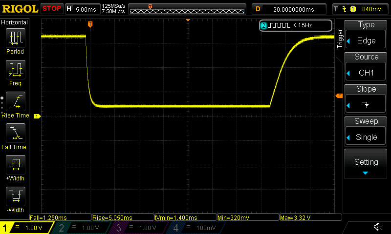
I faced the same issue with a signal from an optoisolator. The unexpected interrupts happened due to a significant rise/fall time. The ESP32 does not work well with curved edges. It needs straight edges to avoid the unexpected interrupts.

There's multiple ways to handle/avoid this issue:

matei-miron commented 11 months ago

Hi, I am experience the same problem. Checked the input with the scope. It is really clean. Had extra caps and resistors added to debounce the signal "just in case". Using 5.1.1

#include "driver/gpio.h"
#include "esp_log.h"
#include "soc/gpio_reg.h"           // For GPIO Registers. GPIO_OUT_REG (31..0) . GPIO_OUT1_REG (32..39) . REG_READ(GPIO_IN1_REG)
#include "freertos/FreeRTOS.h"
#include "freertos/queue.h"
#include "freertos/task.h"

#define crankPin 32
#define wheelPin 33
#define bothPins ((1ULL << crankPin) | (1ULL << wheelPin))

uint32_t wheelRevs = 0;
uint16_t wheelTime = 0;
uint16_t crankRevs = 0;
uint16_t crankTime = 0;
uint32_t wheelRevsOld = 0;
uint16_t wheelTimeOld = 0;
uint16_t crankRevsOld = 0;
uint16_t crankTimeOld = 0;

uint32_t interruptCrankOldTime = 0;
uint32_t interruptWheelOldTime = 0;

static const char *INTTAG = "Register Output:";

static void IRAM_ATTR gpio_isr_handler(void* arg) {
    uint32_t gpioInValue = REG_READ(GPIO_IN1_REG); // Read the whole GPIO input data register
    uint32_t timestamp = xTaskGetTickCount();

    uint32_t data[2];
    data[0] = gpioInValue;
    data[1] = timestamp;

    // Pass the GPIO data and timestamp to the queue
    xQueueSendFromISR(gpio_evt_queue, data, NULL);
}

void updateRecords(void* arg) {
    uint32_t receivedData[2];

    for (;;) {
        if (xQueueReceive(gpio_evt_queue, receivedData, portMAX_DELAY)) {
            //(((receivedData[0] >> 1) & 1) << 1) | (receivedData[0] >> 0) & 1
            uint32_t interruptTime = receivedData[1] * 10;
            uint32_t deltaTimeCrank = interruptTime - interruptCrankOldTime;
            uint32_t deltaTimeWheel = interruptTime - interruptWheelOldTime;

            if ((receivedData[0] >> (crankPin % 32)) & 1) {
                // 250 ms are 4 Hz or 240 rpm.
                if (deltaTimeCrank >= 250) {
                    crankRevs++;
                    ESP_LOGI(INTTAG, "Crank rotations: %u, %lu. Delta: %lu", crankRevs, interruptTime, deltaTimeCrank);
                }
                interruptCrankOldTime = interruptTime;
            }

            if ((receivedData[0] >> (wheelPin % 32)) & 1) {
                // 100 ms are 10 Hz or 600 rpm. About 72 km/h for 29 inch (700C) wheels 
                if (deltaTimeWheel >= 100) {
                    wheelRevs++;
                    ESP_LOGI(INTTAG, "Wheel rotations: %lu, %lu. Delta: %lu", wheelRevs, interruptTime, deltaTimeWheel);
                }
                interruptWheelOldTime = interruptTime;
            }
        }
    }
}

void app_main() {
    esp_log_level_set("*", ESP_LOG_INFO);

    gpio_config_t pinConfig = {};
    pinConfig.intr_type = GPIO_INTR_POSEDGE;
    pinConfig.mode = GPIO_MODE_INPUT;
    pinConfig.pin_bit_mask = bothPins;
    pinConfig.pull_down_en = GPIO_PULLDOWN_ENABLE;
    pinConfig.pull_up_en = GPIO_PULLUP_DISABLE;

    gpio_config(&pinConfig);

    // Create a queue to handle GPIO events from ISR
    gpio_evt_queue = xQueueCreate(10, sizeof(uint32_t[2]));

    // Start the GPIO task
    xTaskCreate(updateRecords, "update_records", 2048, NULL, 10, NULL);

    // Add the ISR
    gpio_install_isr_service(ESP_INTR_FLAG_LOWMED);
    gpio_isr_handler_add(crankPin, gpio_isr_handler, (void*) NULL);
    gpio_isr_handler_add(wheelPin, gpio_isr_handler, (void*) NULL);

    while (1) {
        // Add a suitable delay to control the timing of your application
        vTaskDelay(pdMS_TO_TICKS(1000)); // Example: 1-second delay
    }
}

This produces an interrupt as expected if the signal is applied for a short time. But it produces an interrupt on the raising edge and on the falling edge if the signal is high for a "long enough time". Let's say 1 second. It also panics the core if I set pinConfig.intr_type = GPIO_INTR_HIGH_LEVEL;

MarcinSzymanek commented 4 months ago

Hi, I am experience the same problem. Checked the input with the scope. It is really clean. Had extra caps and resistors added to debounce the signal "just in case". Using 5.1.1

#include "driver/gpio.h"
#include "esp_log.h"
#include "soc/gpio_reg.h"           // For GPIO Registers. GPIO_OUT_REG (31..0) . GPIO_OUT1_REG (32..39) . REG_READ(GPIO_IN1_REG)
#include "freertos/FreeRTOS.h"
#include "freertos/queue.h"
#include "freertos/task.h"

#define crankPin 32
#define wheelPin 33
#define bothPins ((1ULL << crankPin) | (1ULL << wheelPin))

uint32_t wheelRevs = 0;
uint16_t wheelTime = 0;
uint16_t crankRevs = 0;
uint16_t crankTime = 0;
uint32_t wheelRevsOld = 0;
uint16_t wheelTimeOld = 0;
uint16_t crankRevsOld = 0;
uint16_t crankTimeOld = 0;

uint32_t interruptCrankOldTime = 0;
uint32_t interruptWheelOldTime = 0;

static const char *INTTAG = "Register Output:";

static void IRAM_ATTR gpio_isr_handler(void* arg) {
    uint32_t gpioInValue = REG_READ(GPIO_IN1_REG); // Read the whole GPIO input data register
    uint32_t timestamp = xTaskGetTickCount();

    uint32_t data[2];
    data[0] = gpioInValue;
    data[1] = timestamp;

    // Pass the GPIO data and timestamp to the queue
    xQueueSendFromISR(gpio_evt_queue, data, NULL);
}

void updateRecords(void* arg) {
    uint32_t receivedData[2];

    for (;;) {
        if (xQueueReceive(gpio_evt_queue, receivedData, portMAX_DELAY)) {
            //(((receivedData[0] >> 1) & 1) << 1) | (receivedData[0] >> 0) & 1
            uint32_t interruptTime = receivedData[1] * 10;
            uint32_t deltaTimeCrank = interruptTime - interruptCrankOldTime;
            uint32_t deltaTimeWheel = interruptTime - interruptWheelOldTime;

            if ((receivedData[0] >> (crankPin % 32)) & 1) {
                // 250 ms are 4 Hz or 240 rpm.
                if (deltaTimeCrank >= 250) {
                    crankRevs++;
                    ESP_LOGI(INTTAG, "Crank rotations: %u, %lu. Delta: %lu", crankRevs, interruptTime, deltaTimeCrank);
                }
                interruptCrankOldTime = interruptTime;
            }

            if ((receivedData[0] >> (wheelPin % 32)) & 1) {
                // 100 ms are 10 Hz or 600 rpm. About 72 km/h for 29 inch (700C) wheels 
                if (deltaTimeWheel >= 100) {
                    wheelRevs++;
                    ESP_LOGI(INTTAG, "Wheel rotations: %lu, %lu. Delta: %lu", wheelRevs, interruptTime, deltaTimeWheel);
                }
                interruptWheelOldTime = interruptTime;
            }
        }
    }
}

void app_main() {
    esp_log_level_set("*", ESP_LOG_INFO);

    gpio_config_t pinConfig = {};
    pinConfig.intr_type = GPIO_INTR_POSEDGE;
    pinConfig.mode = GPIO_MODE_INPUT;
    pinConfig.pin_bit_mask = bothPins;
    pinConfig.pull_down_en = GPIO_PULLDOWN_ENABLE;
    pinConfig.pull_up_en = GPIO_PULLUP_DISABLE;

    gpio_config(&pinConfig);

    // Create a queue to handle GPIO events from ISR
    gpio_evt_queue = xQueueCreate(10, sizeof(uint32_t[2]));

    // Start the GPIO task
    xTaskCreate(updateRecords, "update_records", 2048, NULL, 10, NULL);

    // Add the ISR
    gpio_install_isr_service(ESP_INTR_FLAG_LOWMED);
    gpio_isr_handler_add(crankPin, gpio_isr_handler, (void*) NULL);
    gpio_isr_handler_add(wheelPin, gpio_isr_handler, (void*) NULL);

    while (1) {
        // Add a suitable delay to control the timing of your application
        vTaskDelay(pdMS_TO_TICKS(1000)); // Example: 1-second delay
    }
}

This produces an interrupt as expected if the signal is applied for a short time. But it produces an interrupt on the raising edge and on the falling edge if the signal is high for a "long enough time". Let's say 1 second. It also panics the core if I set pinConfig.intr_type = GPIO_INTR_HIGH_LEVEL;

The core panicking can happen because while the signal stays high, the interrupt keeps triggering?

MikeJohnsEng commented 3 months ago

There is no Schmitt triggering on ESP32 inputs, interrupts on this MPU need a quick clean transition. I found with slow rise time transitions that interrupts are very unreliable, and even multiple interrupts can be triggered from one event .

It's best to use an external Schmitt trigger buffer.

The STM32 series of MPU's have Schmitt on all inputs which make them a lot more robust, so I'll often interface less than ideal inputs with a Black-Pill and then send the data on to the esp32, works out cheaper than using external Schmitt buffers !

I faced the same issue with a signal from an optoisolator. The unexpected interrupts happened due to a significant rise/fall time. The ESP32 does not work well with curved edges. It needs straight edges to avoid the unexpected interrupts.

There's multiple ways to handle/avoid this issue: ......

uygurrr commented 2 months ago

falling edge and rising edge ramp should be vertical. there should be no capacitor. solution code for FALLING edge: static void kesmeIR() {
if (digitalRead(ir_pin) == LOW) { say++; peryot = micros() - per ; per = micros(); } }