espressif / arduino-esp32

Arduino core for the ESP32
GNU Lesser General Public License v2.1
13.51k stars 7.39k forks source link

Trying to upload voice recognition code, and also helloworld is giving me issues, not sure what to do #1561

Closed PiOrDie closed 6 years ago

PiOrDie commented 6 years ago

Please fill the info fields, it helps to get you faster support ;)

If you have a Guru Meditation Error, please decode it: https://github.com/me-no-dev/EspExceptionDecoder

----------------------------- Remove above -----------------------------

Hardware:

Board: ?ESP32 Heltec_WiFi_Kit_32? Core Installation/update date: ?11/jul/2017? IDE name: ?Arduino IDE? ?Platform.io? ?IDF component? Flash Frequency: ?40Mhz? Upload Speed: ?115200?

Description:

I was trying to upload a voice recognition test on my new esp32 to try it out. I have had no success so I decided to try helloworld, and got an odd message that I don't understand. Also I have tested blink and that works.

Sketch:HelloWorld


//Change the code below by your sketch
#include <Arduino.h>

void setup() { 
 //Initialize serial and wait for port to open: 
 Serial.begin(115200); 

} 
void loop() { 
   Serial.println("Hello ESP32 World!"); 
   delay(2000);

 // put your main code here, to run repeatedly: 
} 

Serial Monitor output: 0x40080310 E (107) spiram: SPI RAM enabled but initialization failed. Bailing out. Hello ESP32 World!

There were also a bunch of question marks, couldn't copy them with the message

Second sketch, the one I'm using to test out the geeetech voice recognition module with the esp32. I know this sketch works since I ran it on my arduino pro nano.

Sketch:VoiceRecognitionTest

byte com = 0; //reply from voice recognition

void setup()
{
Serial.begin(9600);
pinMode(LED_BUILTIN, OUTPUT); // sets the ledPin to be an output
delay(2000);
Serial.write(0xAA);
Serial.write(0x37);
delay(1000);
Serial.write(0xAA);
Serial.write(0x21);
}

void loop() // run over and over again
{
while(Serial.available())
{
com = Serial.read();
switch(com)
{
case 0x11:
delay(1000);
digitalWrite(LED_BUILTIN, HIGH);
delay(1000);
digitalWrite(LED_BUILTIN, LOW);
break;
case 0x12:                         //first case, led on and off
delay(3000);
digitalWrite(LED_BUILTIN, HIGH);
delay(500);
digitalWrite(LED_BUILTIN, LOW);
delay(500);
digitalWrite(LED_BUILTIN, HIGH);
delay(500);
digitalWrite(LED_BUILTIN, LOW);
delay(500);
digitalWrite(LED_BUILTIN, HIGH);
delay(500);
digitalWrite(LED_BUILTIN, LOW);
delay(500);
digitalWrite(LED_BUILTIN, HIGH);
delay(500);
digitalWrite(LED_BUILTIN, LOW);
delay(500);
digitalWrite(LED_BUILTIN, HIGH);
delay(500);
digitalWrite(LED_BUILTIN, LOW);
delay(500);
digitalWrite(LED_BUILTIN, HIGH);
delay(500);
digitalWrite(LED_BUILTIN, LOW);
break;
case 0x13:

break;
case 0x14:

break;
case 0x15:

break;
}
}
}

Debug Messages: 0x40080310

PiOrDie commented 6 years ago

I ran it again and I got a different error message.

load:0x40078000,len:6084 load:0x40080000,len:6696 entry 0x400802e4 E (113) spiram: SPI RAM enabled but initialization failed. Bailing out. Hello ESP32 World!

Again prefaced by question marks that I had trouble copying
PiOrDie commented 6 years ago

Another thing I found is that the tilted IC looks like two of the pins are soldered together, ill upload a picture soon.

PiOrDie commented 6 years ago

here it is https://pasteboard.co/Hs99Z0Y.jpg

PiOrDie commented 6 years ago

Some other sketches made for things such as the display work, I downloaded the U8g2 library and tested out the fullbuffer and the screen is responsive.

lbernstone commented 6 years ago

That SPI RAM error is actually a warning and can be ignored. Weird question mark stuff on the monitor usually indicates a baud rate mismatch.

PiOrDie commented 6 years ago

Alright. Do you know about the voice recognition issues? All I know is that it receives the initial commands to the voice recognition module since it goes in recognition mode, as indicated by the led on the module

lbernstone commented 6 years ago

sorry, my mind reading skills need work. What is the issue?

stickbreaker commented 6 years ago

@lbernstone I think the error is:

E (113) spiram: SPI RAM enabled but initialization failed. Bailing out.

Chuck.

PiOrDie commented 6 years ago

The issue is that whenever I attempt to issue a voice command, the onboard led doesn't turn on. I know that the led works, as I have defined it as pin 25 in a newer version of the voicerecognition code, as that is how I did it in Blink. Although I know that the voice recognition module is receiving commands, it is not responding to a voice command.

stickbreaker commented 6 years ago

@PiOrDie How is the voice recognition board connected to the ESP32?

from the example code it must be connected to Serial()? All of the message you see on the Arduino Serial monitor are also going out Serial(). How does your voice recognition board handle random text as commands?

You might want to connect the VRB to Serial1() and use different gpio pins. I think Serial1() defaults to gpio16&17.

Chuck.

PiOrDie commented 6 years ago

As of now I have it connected to the rx and tx pins, as that was the configuration on my pro mini. I will test your solution when I have access to my computer

PiOrDie commented 6 years ago

How would I connect my vrb to serial1()? I am pretty new at this

stickbreaker commented 6 years ago

@PiOrDie


HardwareSerial Serial1(1); // create Serial1 object, associate it with the Second Hardware Peripheral.

void setup(){
Serial1.begin(9600,SERIAL_8N1,16,17); // Setup the second hardware serial UART at 9600 baud,
  // 8bits, no Parity, one Stopbit
 // gpio16 is RX
 // gpio17 is TX
}

Use Serial1() for all of your communications with the VRD .

Serial1.write(0xAA);
Serial1.write(0x37);
delay(1000);
Serial1.write(0xAA);
Serial1.write(0x21);

Chuck.

PiOrDie commented 6 years ago

tried it, no success. Here is the updated sketch

Sketch:VoiceRecognitionTest


HardwareSerial Serial1(1); // create Serial1 object, associate it with the Second Hardware Peripheral.[
byte com = 0; //reply from voice recognition
int leed = 25;    //for the esp32
//char leed = LED_BUILTIN;
void setup(){
Serial1.begin(9600,SERIAL_8N1,16,17); // Setup the second hardware serial UART at 9600 baud,
  // 8bits, no Parity, one Stopbit
 // gpio16 is RX
 // gpio17 is TX
pinMode(leed, OUTPUT); // sets the ledPin to be an output
delay(2000);
Serial1.write(0xAA);
Serial1.write(0x37);
delay(1000);
Serial1.write(0xAA);
Serial1.write(0x21);
}

void loop() // run over and over again
{
while(Serial.available())
{
com = Serial.read();
switch(com)
{
case 0x11:
delay(1000);
digitalWrite(leed, HIGH);
delay(1000);
digitalWrite(leed, LOW);
break;
case 0x12:                         //first case, led on and off
delay(3000);
digitalWrite(leed, HIGH);
delay(500);
digitalWrite(leed, LOW);
delay(500);
digitalWrite(leed, HIGH);
delay(500);
digitalWrite(leed, LOW);
delay(500);
digitalWrite(leed, HIGH);
delay(500);
digitalWrite(leed, LOW);
delay(500);
digitalWrite(leed, HIGH);
delay(500);
digitalWrite(leed, LOW);
delay(500);
digitalWrite(leed, HIGH);
delay(500);
digitalWrite(leed, LOW);
delay(500);
digitalWrite(leed, HIGH);
delay(500);
digitalWrite(leed, LOW);
break;
case 0x13:

break;
case 0x14:

break;
case 0x15:

break;
}
}
}
PiOrDie commented 6 years ago

What I find odd is that the Voice recognition module is receiving the hex signals, as it goes in the recognition state. I believe it is relaying signals back since it works on my arduino pro mini. This leads me to believe that the esp32 is not receiving the signal back.

stickbreaker commented 6 years ago

@PiOrDie All communications with the VRD need to go through Serial1().

void loop() // run over and over again
{
while(Serial.available())
{
com = Serial.read();

Why do you expect to send commands out Serial1(), but receive responses from Serial()?

Change the Serial() calls in loop() to Serial1().

Chuck.

PiOrDie commented 6 years ago

tried it

/* REMEMBER TO UNPLUG VOICE MODULE WHILE UPLOADING
REMEMBER
TO 
UNPLUG 
IT
REMEMBER TO UNPLUG VOICE MODULE WHILE UPLOADING */
HardwareSerial Serial1(1); // create Serial1 object, associate it with the Second Hardware Peripheral.[
byte com = 0; //reply from voice recognition
int leed = 25;    //for the esp32
//char leed = LED_BUILTIN;

void setup(){
    Serial1.begin(9600,SERIAL_8N1,16,17); // Setup the second hardware serial UART at 9600 baud,
      // 8bits, no Parity, one Stopbit
     // gpio16 is RX
     // gpio17 is TX
    pinMode(leed, OUTPUT); // sets the ledPin to be an output
    delay(2000);
    Serial1.write(0xAA);
    Serial1.write(0x37);
    delay(1000);
    Serial1.write(0xAA);
    Serial1.write(0x21);
}

void loop() // run over and over again
{
    while(Serial1.available())
    {
        com = Serial1.read();
        switch(com)
        {
        case 0x11:
            delay(1000);
            digitalWrite(leed, HIGH);
            delay(1000);
            digitalWrite(leed, LOW);
        break;
        case 0x12:                         //first case, led on and off
            delay(3000);
            digitalWrite(leed, HIGH);
            delay(500);
            digitalWrite(leed, LOW);
            delay(500);
            digitalWrite(leed, HIGH);
            delay(500);
            digitalWrite(leed, LOW);
            delay(500);
            digitalWrite(leed, HIGH);
            delay(500);
            digitalWrite(leed, LOW);
            delay(500);
            digitalWrite(leed, HIGH);
            delay(500);
            digitalWrite(leed, LOW);
            delay(500);
            digitalWrite(leed, HIGH);
            delay(500);
            digitalWrite(leed, LOW);
            delay(500);
            digitalWrite(leed, HIGH);
            delay(500);
            digitalWrite(leed, LOW);
        break;
        case 0x13:

        break;
        case 0x14:

        break;
        case 0x15:

        break;
        }
    }
}
lbernstone commented 6 years ago
/* REMEMBER TO CLOSE ISSUE AFTER RESOLUTION
REMEMBER
TO 
CLOSE
IT
REMEMBER TO CLOSE ISSUE AFTER RESOLUTION */
PiOrDie commented 6 years ago

ok, but im still having the issue, still doesn't recognize voice my bad probably should of said that it didn't work in my last post

lbernstone commented 6 years ago

Ok, now that you have all your VR module comms going over Serial1, you should spit out a bunch of debug to Serial so you can see what is going on. Put a Serial.begin(115200) in your setup, and then put Serial.println (or maybe printf to get your special chars) all through your code to give you better feedback than blinking lights. Make sure you are running on the latest code. I know there was an issue with gpio16 that was fixed the other day due to some changes going on in the codebase.

PiOrDie commented 6 years ago

I am not sure what you mean by putting a Serial.println, as to where to put it. Also I'm not sure how to upload the latest code. I changed the baud rate to 115200

lbernstone commented 6 years ago

This is not the place for arduino tutorials. Please close this issue and use google to lookup how to troubleshoot a device in arduino.

PiOrDie commented 6 years ago

I am confused what u mean by the code, I am aware of how to upload code to arduino, I just thought you meant updating the library, which I am not sure how to do. Can you clarify? If it is the library ill figure it out by myself, but if you mean upload the latest code I wrote to arduino, I have done that. I am now aware of the way to use Serial.print to troubleshoot. I also want to clarify that I didn't make this thread to teach me, I made this thread to solve this issue and to be used as a reference to anyone who runs into this problem.

capedra commented 6 years ago

@PiOrDie have you seen this (https://github.com/greiman/SSD1306Ascii/issues/37) issue? Wire.begin solves a lot of things specially on TTGO boards where it's necessary to use this function to mount the built-in SD cards when using the original SD library for ESP-32.

PiOrDie commented 6 years ago

The only question I have is what I would use it for. In the thread you linked me it says that wire.begin is used to relocate SDA and SCL pins. Also this voice module is connected solely by tx pin, rx pin, 5v, and ground, and has nothing to do with I2C

portasynthinca3 commented 6 years ago

Is your VRB connected to TX0 and RX0 of the ESP32? VRB should be connected to TX1 and RX1 in case of Serial1 usage

PiOrDie commented 6 years ago

I have it connected to pin 16 and 17.

portasynthinca3 commented 6 years ago

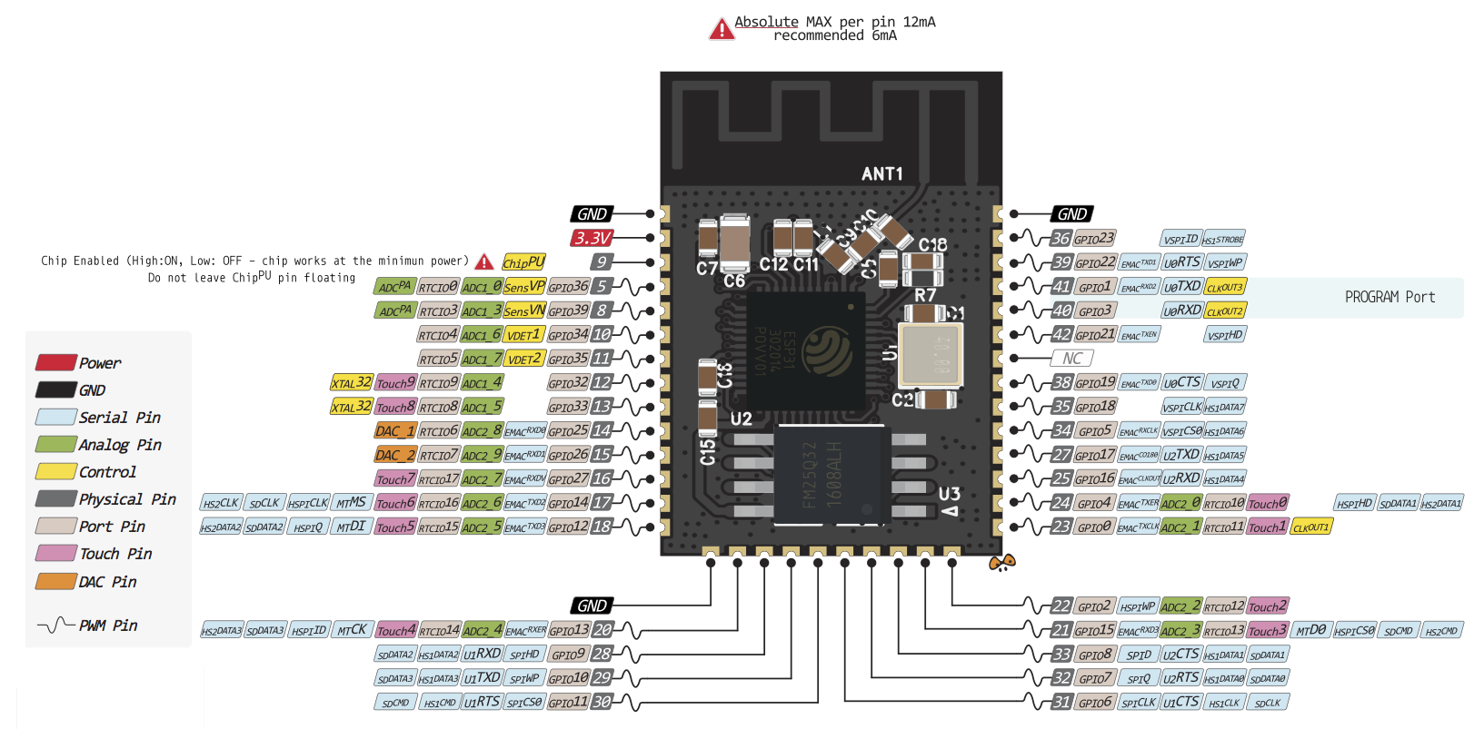
According to this pinout diagram ESP32 GPIO pins 16 and 17 are RX2 and TX2. In this case you should use Serial2 by defining it: HardwareSerial Serial2(2);