 stale[bot]
commented
4 years ago
stale[bot]
commented
4 years ago [STALE_SET] This issue has been automatically marked as stale because it has not had recent activity. It will be closed in 14 days if no further activity occurs. Thank you for your contributions.
 YXGuan
 Argentum238
 csmithy1999
 rmk-homeassistant
 slaveofcode
 ateeq666
 T0b1e
T0b1e y2knbb
 himakarbavikaty
 anvinder
 sansillusion
 ammiredd
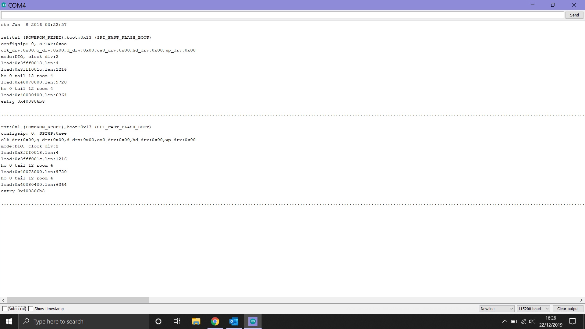
 visalvyasan
 Duswanth
 morebray
 6ReasoN2
After uploading sketch 'CameraWebServer' to the ESP32-CAM using Arudino IDE, I try using the serial monitor to show the IP address of the ESP32, however It just continues to load infinitely with no error code. I've attached an image. The dots just keep on printing and printing.
----------------------------- Remove above -----------------------------
Hardware:
Board: ?ESP32 Wrover Module Core Installation version: ?1.0.0? ?1.0.1-rc4? ?1.0.1? ?1.0.1-git? ?1.0.2? ?1.0.3? IDE name: Arduino IDE Flash Frequency: 40Mhz PSRAM enabled: yes Upload Speed: 115200 Computer OS: Windows 10
Description:
Describe your problem here
Sketch: (leave the backquotes for code formatting)
Debug Messages: