Hi Sydney
I have not worked with the lib in a while. As far as I remember, I used to change the data rage successfully in the using Init function call as here. Furthermore, I used the ADS125X_Register_Read function extensively inside the library during debugging, which is why it should work.
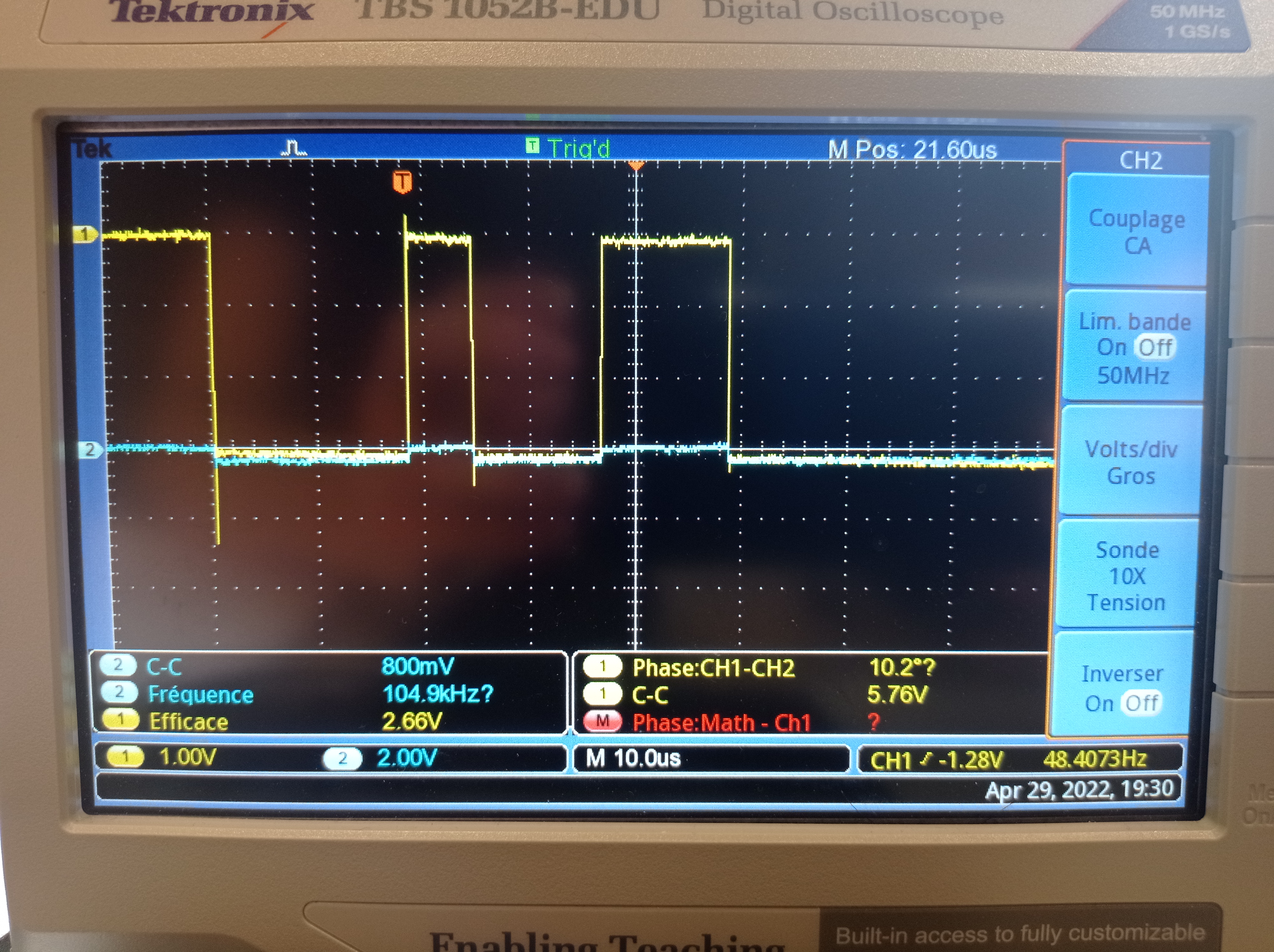
1° Why is there some data on the DIN that looks more or less identical (with some late) to the DOUT ?
The blue signal seems to be in a Z-state before being forced high by the half bit. Not sure why. Maybe the STM32 SPI configuration sends back the received data as ACK, but that does not make sense because yellow is high before the blue signal exits the Z-state. Or maybe (although unlikely) you write to the same variable as the outgoing data. Are your sure the wiring is absolutely correct, I am worried because the high state of the blue signal is 0.5V smaller for the half bit than it is for the rest of the signal.
How much of what we can observe is not normal ?
The behaviour with the copied data on the other data line can be correct or incorrect. I would have to know the signals and would need to dig into the datasheets. But as I said, the lib and functions worked on my hardware.
Have you ever seen similar problem ?
Usually when there is a "bit shift" error in transmitted or received SPI data, it is because of the wrong SPI config (clock polarity and clock edge alignment). But I am not sure if that is the case here since the voltage is read back correctly according to you.
Dear Simon,
During my intership for my electronic degree, I'm using the LC Technology ADS1256 board with a Nucleo-F401RE and I can't manage to read a register. Using your library i'm able to read the voltage but the value that i get when using the ADS125X_Register_Read function is wrong.
Disclaimer : I haven't modified the library and both boards should be working fine
For instance,
After trying to read as carefully as possible the datasheet, i concluded the theoretical transaction should be :
Here are my observations with my oscilloscope : (Yellow is DIN and Blue is DOUT)
I believe the first image is beginning of the transaction (the query) which is identical as the theoretical that i talked about above. On the image, we can't see the end of the 2nd byte but it keeps on being 0.
However, in the answer from the ADS1256, there is a few things i don't get. 1° Why is there some data on the DIN that looks more or less identical (with some late) to the DOUT ? 2° We can see on the blue channel that the first bit is halfed. 3° If we were to forget and the first halfed bit and focus on the rest we would actually get 0b00100011 which is, according to the datasheet, the right value.
Therefore i'm guessing that the issue is located during the receiption.
About the SPI2 bus on the Nucleo-F401RE board : I believe the default speed is 42 MHz and I'm using an 64 prescaler to slow it down. Also, my wiring should be correct.
How much of what we can observe is not normal ? Have you ever seen similar problem ?
I guess i'm doing something wrong but somehow I can't point it. As far as i know, your library since to be working fine since the beginning of the SPI transaction seems correct.
Best regards, Sydney ROBAUX