 scottnolde
commented
4 months ago
scottnolde
commented
4 months ago Update: I found the issue and everything is working as it should be. Turns out that the solderless breadboard that I purchased was the issue, the power and ground rails that go along the sides of the breadboard are cut in the middle. I needed to put a jumper wire to connect the power for the PCF8574 IC's. I have two other solderless breadboards that are not like this. So connecting the I2C data to the PCF8574 IC's was preventing the I2C data to flow along the data buss. This prevented the Nano from booting up. Rookie mistake I know, but the VFO is working properly.
I am still wondering about the I2C address difference. I set the address on the PCF8574's to 20 (the default from the factory) and 21. Then the outputs work fine. Some trial and error was needed to get this part to function properly. I see address 32 and 33 in the code but the 8574's jumper settings only allow for address 20 thru 27. Could someone take the time to point me to the documentation that will help me to understand please? Thanks and 73, Scott
 fcisotta
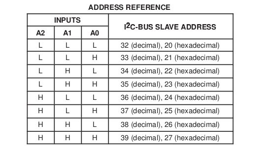
Hi, Thanks for providing the SI5351 VFO project. I have built the circuit and loaded the programming into a Arduino Nano. The SI5351, the Rotary Encoder and the LCD are working properly, also the Button functions are working properly. My problem is the PCF8574 chip. When it is in the circuit the Nano will not boot. I do not get a display on the LCD at all. The circuit does have power though. LCD back lighting comes on and the power indicator on the Nano lights up. I do have a question regarding the addressing of the 8574 chips. The 8574"s can only be addressed from 20 thru 27 using pin jumpers. The program was set to addresses in the 30's. I tried the system using the addresses in the program without any changes and with changing the addresses to 23 and 24 both in the software and on the 8574. Had the same issues both ways. I have verified the wiring to be correct multiple times and did not find any problems. I did test the PCF8574 chip by building a test circuit Sketch and they preformed properly, Blinking LED's on each port. If you have any questions feel free to ask. Thanks again for the project it will go nicely into my next Ham Radio project. 73 Scott KG4RLL