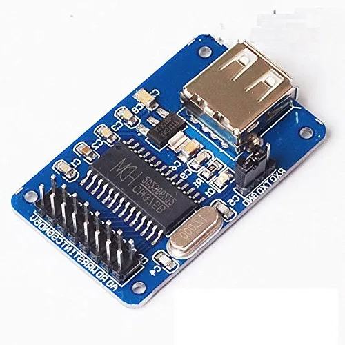
The reason is that the CH375 part in that schematic is not a bare CH375 chip but a breakout board like the one picured below, with built-in USB socket. Thus the pins on the Fritzing part are just the exposed pins on the breakout board.
The unconnected ones are not needed. The chip supports both a serial and a parallel communication mode, and the library used in the sketch only uses the serial mode, thus the parallel data and control lines are left unconnected.

On the fritzing file for the USB connection using CH375, "fritzing-usb-ch375.fzz", some of the pins on the CH375 do not have labels. There is also no indication on the connection for the pins between the USB socket and the CH375. Please help to clarify these.