Open tmzqvd opened 3 years ago
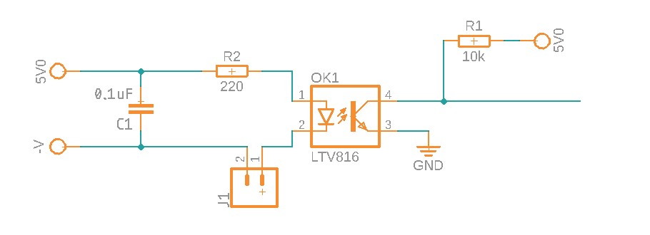
The cap must go on the transistor side of the opto, to slow down transitions.
El El lun, 12 de abr. de 2021 a la(s) 10:04, tmzqvd < @.***> escribió:
I know it's a trivial question. But I got confused following instructions on Wiring Limit Switches https://github.com/gnea/grbl/wiki/Wiring-Limit-Switches. Can someone please clarify the location of capacitor. NC switch configuration. Two separate power supplies.
First option: [image: limit_switch_option_1] https://user-images.githubusercontent.com/26189413/114397882-73cf4180-9b9f-11eb-87b4-0dd5d3af638d.jpg
Second option: [image: limit_switch_option_2] https://user-images.githubusercontent.com/26189413/114398139-bdb82780-9b9f-11eb-91e1-f2a13bf585bf.jpg
Or none of them?
Thanks.
— You are receiving this because you are subscribed to this thread. Reply to this email directly, view it on GitHub https://github.com/gnea/grbl/issues/1030, or unsubscribe https://github.com/notifications/unsubscribe-auth/ACXBW4KA55NQDZNA6ZXF74DTILVUVANCNFSM42ZICR5Q .
Do you mean like this?
This was my first idea. But then I read this post limit switch trigger report (user biletnikov stated "In your case, I would suggest to add 0.1 uF capacitor in parallel to the contacts of switch.") and the schema he made Limit Switch board for CNC machines. I don't like the way he's wiring switches therefore I want to make my version.
Maybe I should mention that right side of opto will be near arduino - the same pcb as arduino will be placed.
Yes, that is the way. When opto goes on C1 discharg. As it goes off C1 charge from 10k R1 and takes more than 1mS .
El El mar, 13 de abr. de 2021 a la(s) 10:26, tmzqvd < @.***> escribió:
Do you mean like this?
[image: limit_switch_option_3] https://user-images.githubusercontent.com/26189413/114558532-11437780-9c6b-11eb-88ce-3b4696f0de31.jpg
This was my first idea. But then I read this post limit switch trigger report https://github.com/gnea/grbl/issues/852 (user biletnikov stated "In your case, I would suggest to add 0.1 uF capacitor in parallel to the contacts of switch.") and the schema he made Limit Switch board for CNC machines https://hackermagnet.com/limit-switch-board-for-cnc-machines/. I don't like the way he's wiring switches therefore I want to make my version.
— You are receiving this because you commented. Reply to this email directly, view it on GitHub https://github.com/gnea/grbl/issues/1030#issuecomment-818734620, or unsubscribe https://github.com/notifications/unsubscribe-auth/ACXBW4LRRVT4W2KCNHPJF4TTIRBBRANCNFSM42ZICR5Q .
Thanks. What about putting capacitor on both sides of opto? Does it make any sense? If yes how to put it on left side? First or second option? Let me explain why I think it's good to have it on switch side (left) of opto. Switch is on cnc machine and wires goes with other wires and also there is a spindle motor. Opto will be at the end of switch wires, next to arduino. Therefore I think problems are generated on that side. Maybe it's best to prevent false signals even comming to opto. I will not put this circuit next to switch, but next to arduino. They will be on the same pcb.. Relative long wires will come from switch to this circuit.
I added another option - 4. I think these are all. At present moment I'm leaning towards 3 and 4 combined. What do you think?
It's obvious I don't have enough theoretical knowledge.
Only option 4 of the above makes any sense. The only reason for the capacitor is shorting the bounce of the switch. The only place it can do that is directly parallel to the switch,
i read you are using this circuit on an arduino, Use the pinMode ( pinNumber , INPUT_PULLUP ); and lose the 10K pullup resistor R1 in the schematic of option 4.
Thanks @RonaldDegenkamp. Is INPUT_PULLUP reliable? Is it working on nano? I have never used it. I'm always using classical INPUT with added resistor. I will use grbl and I'm not sure it's using pinMode ( pinNumber , INPUT_PULLUP ). Or maybe I can set it to work this way. Have to check.
INPUT_PULLUP is the most reliable way and works on a nano. GRBL uses INPUT_PULLUP on all input pins exept 13 where the onboard led is connected (on UNO)
The 5v supply and the associated GND on the switch side of the optocoupler must be a separate supply otherwise there is NO isolation. This has to be a completely separate supply.
I know it's a trivial question. But I got confused following instructions on Wiring Limit Switches. Can someone please clarify the location of capacitor. NC switch configuration. Two separate power supplies.
First option:
Second option:
Or none of them?
Thanks.
p.s.: after 3 days I realized I posted two identical options. I corrected second option.