Open EducatingSavvas opened 6 years ago
See the cpu_map.h file. There are some max and min PWM values you can alter. The values mean 0 = 0V and 255 = 5V. You can also enable the piecewise linear spindle option in config.h to follow a nonlinear voltage and RPM output. There are instructions to help you calculate the constants for that, if you need it.
Sorry misread your post. Your Grbl output only ranges from 2V - 5V. This isn't right. It defaults to cover 0V to 5V. There must be something wrong with your settings, made improper alterations, or an electrical problem.
Thanks I think I spotted it in the cpu_map.h file. Line 129, PWM min value was set to 5. So the PWM min value in the config.h file refers more to the voltage resolution within that range. I will flash the firmware tomorrow morning and hopefully that will do it.
So that didn't work. I think my problem is to do with scaling the PWM signal so it goes from 0-100%. At the moment is goes from 0 and jumps to nearly 50%, and the linear control only between 50-100%.
What are the PWM settings in cpu map and your RPM settings in $$?
Post your schematic. Especially the thing about a smoothing capacitor. This behaviour sounds like a blown low-side pin driver on pwm output, which might happen if your circuit is wrong...
RPM settings in $$ are $30=24000 and $31=0 and PWM settings are SPINDLE_PWM_MAX_VALUE 255 and SPINDLE_PWM_MIN_VALUE 1. Please let me know if there are more specific settings / lines you want to see? I don't have a proper schematic apart from what's on the tindie website for the controller: https://cdn.tindiemedia.com/images/resize/uGIh6DmBfqm4S8SiFXAJ68ZCkJY=/p/full-fit-in/2400x1600/i/43454/products/2017-10-28T19%3A14%3A06.353Z-Wiring%20Diagram.png
@biasedlogic I also checked the output signal voltage from the Arduino chip itself.
Ever get this resolved? Just wondering as I have spent a few hours tuning the PWM output on mine to where its almost perfect. Always looking for tweaks though.
That board looks like it uses an op amp to modify the PWM output. Thats why it offers 0-5V or 0-10V out and ships with 0-10V as default.....
Probably uses that lm358 to shift the pwm. It would be sensitive to pwm frequency too.
If you still need help with this then have a look here: https://www.cnczone.com/forums/news-announcements/287196-cnc-software-forum.html It's a post from the designer of the Phoenix CNC Controller. You will probably have to register on the forum before you can post anything.
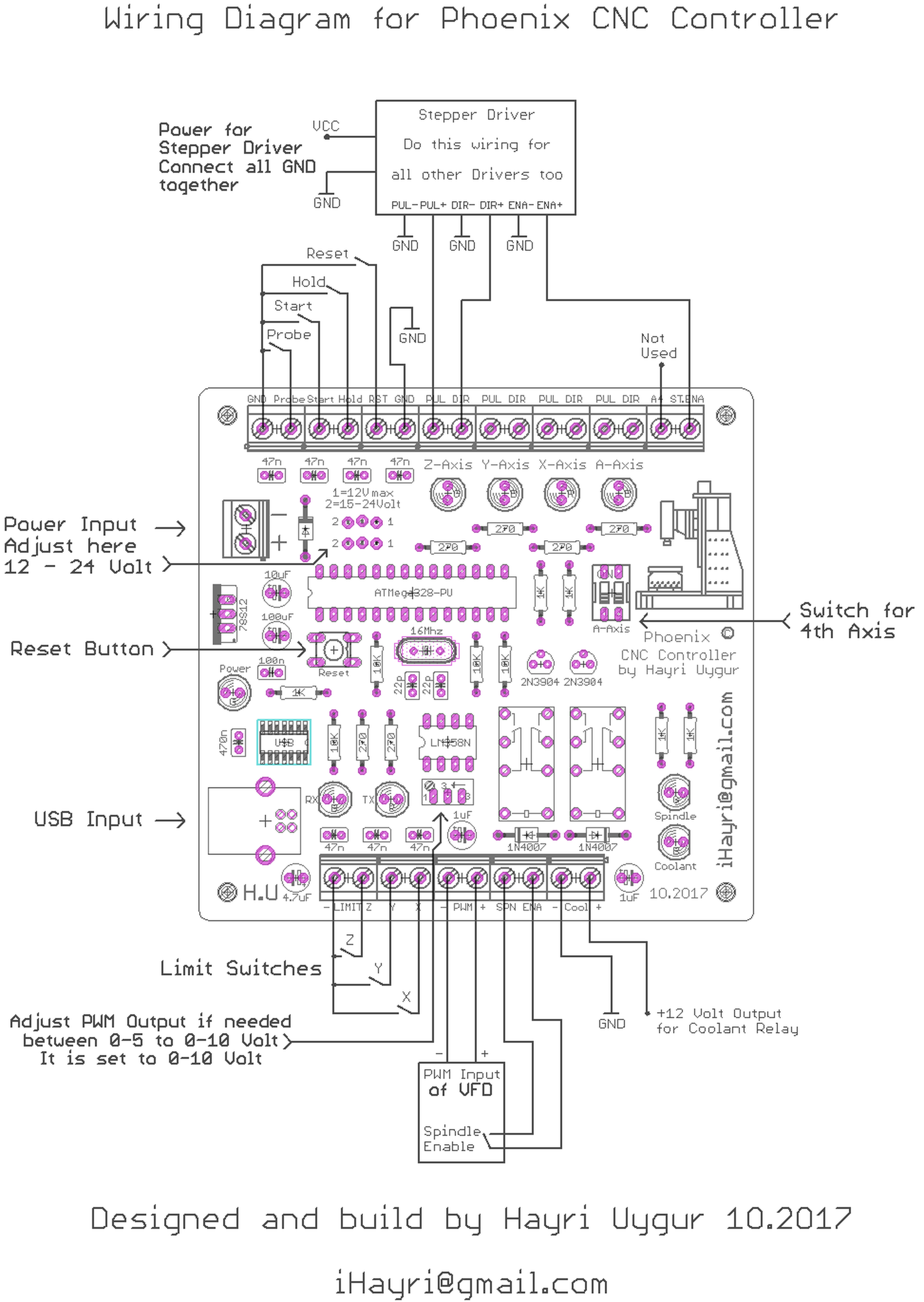
Hi - I am running GRBL V1.1 on a Phoenix CNC controller which was built primarily to use with VFD milling. It has a smoothing capacitor to change the PWM signal so it is more like the analogue signal the VFD expects. However I am trying to use the controller for both milling and laser engraving. Luckily my laser engraver can accept both TTL and analogue in. The problem I am having is the PWM voltage range seems to only go between 2-5v from the controller and I can't tell what I need to adjust in the firmware. I have changed the base frequency for the laser and the min_PWM to 1. At the moment I am using a air cooled spindle and the 2v signal produced roughly the correct minimum RPM but 0-5v control for a laser would be more useful. so I can't tell if this is a failsafe built into the controller or a failsafe in the firmware. Any pointers regarding overriding this would be welcomed. Thanks, S