 whitequark
commented
3 years ago
whitequark
commented
3 years ago This is designed to plug directly into a host, but the Type-C paddle mounted connectors mean we're forced to use a 0.8mm PCB, and the overall design feels a bit flimsy. Potentially a 3d printed case might help?
These are exactly my thoughts--I think I was going to file a bug but forgot.
Would it be possible to use two Type-C sockets, and then maybe house the device in a small extruded aluminum case as shown?
Unfortunately, I don't think two sockets will work. If you are using something that requires e-marked cables, I think (based on my understanding of the PD spec) that will just garble the communication since there's only SOP' and SOP'' to address the markers. Also, if you are using something like Thunderbolt, two cables plus the PD sniffer PCB might exhaust the entire link budget. I am very interested in using it for both of these applications.
The latter reason also excludes e.g. having two connectors with a mux picking between them, since you cannot pick a mux that handles every conceivable altmode. The board has to stay passive and functional with only a single cable involved, or it will lose a lot of its usefulness.
I think a sturdy case, 3d printed or not, is the way to go. I expect some boards will break during use, but... it's not a complex or expensive board (now that we aren't using Google's absurd design rules) so it's not a huge loss. In any case, plugging suspicious type-C stuff into a type-C debugger directly electrically interfacing the lines is inherently hazardous. We don't even have protection from having 20V on the CC lines; anyone using this sniffer ought to buy them in pairs!
 hardkrash
 gregdavill
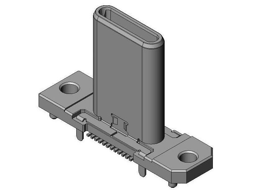
 electroniceel
 dnschneid
 dojoe
dojoe
The current design features an upstream Type-C plug and downstream Type-C socket.
This is designed to plug directly into a host, but the Type-C paddle mounted connectors mean we're forced to use a 0.8mm PCB, and the overall design feels a bit flimsy. Potentially a 3d printed case might help?
Would it be possible to use two Type-C sockets, and then maybe house the device in a small extruded aluminum case as shown?