gregsaun / prusa_i3_bear_upgrade

Stronger frame for Prusa i3 MK2(s), MK2.5 and MK3
GNU General Public License v3.0
960 stars 343 forks source link

how to apply MK4 upgrade on Bear 2.1 #138

Open bgiot opened 1 year ago

bgiot commented 1 year ago

Hi, it's more a question: I have a bear 2.1 mk3s with bondtech extruder. Will the MK4 upgrade work outofthebox ? Or do I have to comeback to the original frame design and wait for bear 3.0 design ?

akbiocca commented 1 year ago

The MK4 is printing at the moment for a few hours, but if you refer to the vertical distance, that's about 10mm from the tip of the nozzle to the underside of the bearing clamp. That's just an eyeball estimate. It's about 6mm vertically tip to cooling duct, and then a few more to the bearing clamp. I don't know if pictures get through here but I can get some if that is useful.

On Sat, May 20, 2023 at 9:31 AM Grégoire Saunier @.***> wrote:

@DesC21 https://github.com/DesC21 This is promising, 13.9mm seems to be more than the nozzle <-> X carriage distance. This is promising! And good news for the cable holder!

@akbiocca https://github.com/akbiocca do you think you could roughly estimate the space between nozzle and bottom of the X carriage?

— Reply to this email directly, view it on GitHub https://github.com/gregsaun/prusa_i3_bear_upgrade/issues/138#issuecomment-1555947279, or unsubscribe https://github.com/notifications/unsubscribe-auth/A3AIDK5DUMMZ2VMJWN26B4LXHDWW3ANCNFSM6AAAAAAWM2Y2GI . You are receiving this because you were mentioned.Message ID: @.***>

gregsaun commented 1 year ago

@akbiocca looks promising. Take your time, no stress at all

akbiocca commented 1 year ago

MK4 Measurements

using the Z axis motion control with a resolution of 1mm fitting a 20mm cube on the print bed under these items: nozzle 21mm (didn't quite clear at 20mm, probably very close) air duct 15mm (6mm higher than nozzle) bearing cap 14mm (7mm higher than nozzle)

On Sun, May 21, 2023 at 12:30 AM Grégoire Saunier @.***> wrote:

@akbiocca https://github.com/akbiocca looks promising. Take your time, no stress at all

— Reply to this email directly, view it on GitHub https://github.com/gregsaun/prusa_i3_bear_upgrade/issues/138#issuecomment-1556106828, or unsubscribe https://github.com/notifications/unsubscribe-auth/A3AIDKYHIZ2SWMUDOOFTCCDXHHAA3ANCNFSM6AAAAAAWM2Y2GI . You are receiving this because you were mentioned.Message ID: @.***>

gregsaun commented 1 year ago

Those are great news, sounds like we can make the bear compatible with MK4. Thank you very much @akbiocca for those measurements

PatB42 commented 1 year ago

Alors Grégoire, comment va? ça fait plaisir de te lire dis donc.. La Suisse peut encore compter sur toi !! ;-) j'espère que tu récupères bien !! So i followed some of the comment and just to know where we are at now and IF i can help on some design or test .. at know i have 1 question it's about the dimension , size of the xbuddy apparently the mk4 come with metal box ? but as we like and i like to have my own design for such item is someone have it especially the hole for screwing .. as said if there is other part that needs to be redesign or tested i can do too...i only use fusion360 so i can share after the stl or f3d files or step too..alors voilà..;

PatB42 commented 1 year ago

By the way Greg it's start to be difficult to find the 2.1kit frame ...only in UK but UK UK UK ..it's far now from France and dhl , fedex take huge fee only to do the invoice.. the last new one are nice in spain but not too much color...

DesC21 commented 1 year ago

@PatB42 I will post my parts on printables shortly. I made some minor fixes to the z-tops since the last update but it's looking good now I think. I will print the first parts over the weekend to check that it prints without issues. What I am still missing is the mounting parts for the new metal electronics box. I'll design some mounting parts for the original metal box.

@akbiocca thanks for the measurement, that's sounds all good for our bears. Could you maybe measure the dimensions of the new electrronics box and the position of atleast one screw to the edges of the box (see images, these should be easy accessible, for the top screw it would be good to now the position to the top and right edges of the box, for the bottom screw bottom edge instead of top edge of the box)? Some rough numbers will suffice for the first version, no need to unscrew the box ;). thanks in advance! image

akbiocca commented 1 year ago

Measurements on my MK4:

Electronics Box (on the left side viewed from the front) X dimension, outside, just under 48mm, not including screwheads that protrude on the left side Y depth approx 106mm, not including wifi module cover protruding to the rear Z height approx 133mm for the box, not including cable support on the top of the box

Mounting Holes from the front it appears that four threaded frame holes are used for mounting the box horizontal spacing in X appears to be 38mm vertical spacing in Z appears to be 93mm spacing of the left most mounting holes from the left edge of frame appears to be 5mm (edge to center) frame width in X in this area appears to be 49mm lower hole to table surface is a bit over 76mm

Measurement tools were Mitutoyo scale and digital calipers, errors are mine.

Regards, Alan

On Fri, Jun 2, 2023 at 2:29 AM Dennis Schuldt @.***> wrote:

@PatB42 https://github.com/PatB42 I will post my parts on printables shortly. I made some minor fixes to the z-tops since the last update but it's looking good now I think. I will print the first parts over the weekend to check that it prints without issues. What I am still missing is the mounting parts for the new metal electronics box. I'll design some mounting parts for the original metal box.

@akbiocca https://github.com/akbiocca thanks for the measurement, that's sounds all good for our bears. Could you maybe measure the dimensions of the new electrronics box and the position of atleast one screw to the edges of the box (see images, these should be easy accessible, for the top screw it would be good to now the position to the top and right edges of the box, for the bottom screw bottom edge instead of top edge of the box)? Some rough numbers will suffice for the first version, no need to unscrew the box ;). thanks in advance! [image: image] https://user-images.githubusercontent.com/26366384/242844730-538c34b9-92d8-4117-b373-df3a65eb4a89.png

— Reply to this email directly, view it on GitHub https://github.com/gregsaun/prusa_i3_bear_upgrade/issues/138#issuecomment-1573433684, or unsubscribe https://github.com/notifications/unsubscribe-auth/A3AIDK6EXMZGR4EAJ3Q6GHLXJGW5ZANCNFSM6AAAAAAWM2Y2GI . You are receiving this because you were mentioned.Message ID: @.***>

DesC21 commented 1 year ago

@akbiocca that's perfect, thank you very much!!

Quick update z-motor mount and z-tops print nicely. The lcd supports need some improvements. I also printed the lcd cover to check the collision (which is also in the prusa parts), I'll have to double check if this is okay and then I'll start with the buddy case mounting. First release is coming closer but still takes a bit more time.

DesC21 commented 1 year ago

quick peek at the xBuddy case mounting. Not ready yet but should work with four identical parts (just mirrored). image image

@akbiocca one more thing, can you please check the position of the holes to the top edge of the case? Right now I assumed it's just exactly in the middle but it's just a guess ;-). See this sketch And maybe the thickness of the case walls (so I can make the default screw length work) image PS.: I got my old mk3 frame out and measured holes in the frame without screws. That's why the other measurements are slightly different to your measurements.

gregsaun commented 1 year ago

@PatB42 Si tu es de Suisse je peux peut-être t'avoir un frame. Sinon il y a aussi 3D Boom qui en a peut-être encore quelques-uns: https://www.3dboom.es/ldo-motors/343-2113-marco-bear-ldo-21-kit-actualizacion-para-mk2s-mk25s-mk3s.html#/11-color-negro . LDO est busy avec Voron et Prusa en ce moment malheureusement.

@DesC21 The MK3 and MK4 frames should have the same screw positions for everything, including the electronic. If you look at the MK3S+ assembly they have now added two possible frames, old MK3 and new MK4. They do this because they want to have a single frame and not have to manufacture two of them (need some for replacement parts and latest MK3S+ sales). Check the last point on the Introduction guide here: https://help.prusa3d.com/guide/1-introduction_176529#420565 . Here is the MK3S+ assembly guide with the MK4 frame: https://help.prusa3d.com/guide/2a-y-axis-assembly_406654 . I have also confirmed with the support that Z top and Z bottom screw holes are at the same position on both frame, so they share the same printed parts.

Thanks for all your work, it looks to progress well 👍

On my side I did clean some STL parts to have solid holes and being able to have a MK4 as reference. I had to redraw from scratch the cable holder as the STL conversion wasn't good (they are not 100% identical but differences are way bellow printed part tolerances).

mk4_r1_assembly_01

mk4_r1_assembly_02

I could then measure the Z axis smooth rods distance and I have 325.50mm :

mk4_r1_assembly_03

This was a little surprising as @akbiocca did measure 328mm and he also said there were a little rubber too if I recall correctly. So I have contacted the Prusa support again and they told me the smooth rods are 325mm long.

I have attached the a STEP of the MK4 assembly for those that want to play with it. Unfortunately the F3Z is too big to be attached here (can share it somewhere else if useful). mk4_assembly_r1_v01.zip

On side note, after looking more in details I am not much convinced by this new nextruder so I will keep going on the BearExxa V2 and I am not planning to move to MK4 for now. I hope the new electronic and firmware (MK3.5 upgrade) will support the E3D Revo.

DesC21 commented 1 year ago

@gregsaun so good to see you back on the PC!!! Yes, that's why I measured my old frame, good to have it confirmed by Prusa. It's just that the xbuddy case is a complete black box right now, since there is documentation on. I mean I can easily screw it to bear frame with the parts but I would like to have it centered without collisions ;).

I do not understand why they went with the longer rods. That means that MK3.5 and MK3.9 with the old rods will have a different z-height? Might explain why it is easily changeable in the menu... Thanks for the step file I will check it and compare it to the MK3 to see what I can do for the z-top/motor mount. I am not sure where these 5mm go right now, My guess would be that the motors are lower., BTW are the MK4 z-motors also longer?

Looking forward to see what you come up with BearExxa V2.

akbiocca commented 1 year ago

I wonder if there is a few mm of plastic in the lower Z motor mount separating the bottom end of the rod from the rubber on top of the motor. That could account for 325mm rods. There is some plastic on top of the Z rod in the upper rod mount, but there is a hole so you can see the end of the Z rod so I tried to compensate for that end. The other end is buried in plastic.

I get about 19mm from the center of the top mounting hole to the top of the electronics box.

On Mon, Jun 12, 2023 at 11:48 AM Dennis Schuldt @.***> wrote:

@gregsaun https://github.com/gregsaun so good to see you back on the PC!!! Yes, that's why I measured my old frame, good to have it confirmed by Prusa. It's just that the xbuddy case is a complete black box right now, since there is documentation on. I mean I can easily screw it to bear frame with the parts but I would like to have it centered without collisions ;).

I do not understand why they went with the longer rods. That means that MK3.5 and MK3.9 with the old rods will have a different z-height? Might explain why it is easily changeable in the menu... Thanks for the step file I will check it and compare it to the MK3 to see what I can do for the z-top/motor mount. I am not sure where these 5mm go right now, BTW are the MK4 z-motors also longer?

Looking forward to see what you come up with BearExxa V2.

— Reply to this email directly, view it on GitHub https://github.com/gregsaun/prusa_i3_bear_upgrade/issues/138#issuecomment-1587887825, or unsubscribe https://github.com/notifications/unsubscribe-auth/A3AIDKYOOEZBBHWFU3BA32LXK5QBBANCNFSM6AAAAAAWM2Y2GI . You are receiving this because you were mentioned.Message ID: @.***>

gregsaun commented 1 year ago

@DesC21 I try to push myself to go back but I can only do small tasks. For the case collisions, don't go further inside (against the bed) than Bear 2.1 printed part.

For the Z axis length, MK3.5 is 210mm and MK3.9 is 220mm according to this table: mk4_upgrades_01 So I think MK3.5 will not use 10mm smooth rods but MK3.9 will. It is still confusing as on the list of included parts here the 10mm smooth rods are missing but in the top description they say "MK3.9 contains everything from the MK4 except for the X/Y/Z motors (Nextruder motor is included)".

It is a good idea to move to longer smoother rods as you can better hold them with printed parts (more plastic to grab the rod). The Z motor mount are thicker for that reason. The leadscew should have the same length, there are margin there as the nut does not move all to the top.

@akbiocca I think I did understand wrongly before, so the plastic on top of Z motor mount is the printed part itself right? Yes there is also a bit of the same geometry in the motor mount. Did you remove the smooth rod entirely when you did measure the length?

akbiocca commented 1 year ago

Both motor mount and Z rod top mount appear to be printed plastic parts

I did not disassemble anything on the MK4 to make any of these measurements, and since this was a factory pre-assembled unit I did not have the opportunity to measure them separately. I'm measuring the Z rod with a metric tape measure from the bottom of the motor mount to the top of the Z rod mount. I subtracted some for the top mount as I can see the end of the rod through a hole in the top Z mount as the top Z mount goes above the end of the Z rod. I can't see the Z rod bottom end but if the rod is 325mm then there must be some printed plastic between the lower end of the Z rod and the rubber that is on the face of the motor, and this would be consistent with the design of the top, and designed to keep the Z rod from contacting the rubber directly which makes sense. The lower end of the Z rod would essentially be enclosed by a pocket in the printed motor mount.

Thanks for the thorough work on this.

-- Alan B

On Tue, Jun 13, 2023 at 2:21 AM Grégoire Saunier @.***> wrote:

@DesC21 https://github.com/DesC21 I try to push myself to go back but I can only do small tasks. For the case collisions, don't go further inside (against the bed) than Bear 2.1.

For the Z axis length, MK3.5 is 210mm and MK3.9 is 220mm according to this table: [image: mk4_upgrades_01] https://user-images.githubusercontent.com/12335098/245417630-37da4600-13d4-4f29-a953-0087dce3a426.jpg So I think MK3.5 will not use 10mm smooth rods but MK3.9 will. It is still confusing as on the list of included parts here https://www.prusa3d.com/product/original-prusa-i3-mk3-s-to-mk3-9-upgrade-kit/ the 10mm smooth rods are missing but in the top description they say "MK3.9 contains everything from the MK4 except for the X/Y/Z motors (Nextruder motor is included)".

It is a good idea to move to longer smoother rods as you can better hold them with printed parts (more plastic to grab the rod). The Z motor mount are thicker for that reason. The leadscew should have the same length, there are margin there as the nut does not move all to the top.

@akbiocca https://github.com/akbiocca I think I did understand wrongly before, so the plastic on top of Z motor mount is the printed part itself right? Yes there is also a bit of the same geometry in the motor mount. Did you remove the smooth rod entirely when you did measure the length?

— Reply to this email directly, view it on GitHub https://github.com/gregsaun/prusa_i3_bear_upgrade/issues/138#issuecomment-1588895213, or unsubscribe https://github.com/notifications/unsubscribe-auth/A3AIDK4OHB7OYCQ7RJEA5U3XLAWLJANCNFSM6AAAAAAWM2Y2GI . You are receiving this because you were mentioned.Message ID: @.***>

gregsaun commented 1 year ago

@akbiocca Thanks, that is all clear now and explain the length difference. Yes I confirm there is similar design in the Z motor mount and the thickness is 1.5mm : z_motor_mount_01 You also have a small hole on the external side where you can see if the rod is fully inserted.

I can confirm your 328mm as well on my assembly: z_motor_mount_02

For your information, the part on the motor fixed to the leadscrew is to protect the motor bearing from dust.

DesC21 commented 1 year ago

@gregsaun thanks for the insight, that does make sense :-).

It's quite the mess with the different variants and the inconsistent infos. But I think the MK3.5 only has 210mm Z because it doesn't have the Nextruder (MK3.5 keeps the V6 hotend). So if you are upgrading to MK3.5 all the old Bear parts (z-axis) should work (you "only" get the new 32-bit board).

The 3.9 kit is the black box right now because the description is inconsistent. It would make sense if you get new z-rods because otherwise you would actually need the zmotor mounts and z_tops for 8mm rods with 320mm length and Prusa also needs to release different x-idler and x-ends parts than the MK4 parts we currently have. But if you get new z-rods, you can also use the MK4 printed parts, which would make a lot more sense.

For a full MK4 we definitively need different parts with 10mm rods and 325mm length. The parts I did are for 320mm rods so I need to fix that.

So my understanding is, yes the MK4 (and almost certainly the MK3.9) z-rods are 5mm longer but it won't change the z-height, it's just an improvement for the reasons you stated Greg.

I read that the first kits are shipping so I will check and try to hurry up with fixing the z-parts for the full MK4 bear and release everything on printables.

DesC21 commented 1 year ago

@gregsaun I just checked the z-axis. I used your step file and added the old MK3 parts to see what they did to get the 5mm. And I noticed that I get this weird ~322,5mm for the MK3. Do you remember if this was normal (I was expecting something closer to 320mm)? image

So anyway, for the missing additional 2,5mm they changed the z-tops. Motor position (top) is the same height but the rod is 0.3mm lower on the MK3 (I'll keep the old bear design though) .

gregsaun commented 1 year ago

@DesC21 Can't wait to see the mess with MK3.5, MK3.5S, MK3.5S+, MK3.9, MK3.9S, MK3.9S+, MK4, MK4S, MK4S+ :D

Ideally I would like to do MK3.5 + 325x10mm smooth rods with the current Bear X and Z axis modified to accept 10mm, the 0.9 motors and the BearExxa V2. I don't care much if it is 200mm, 210 or 220mm personally.

Good check for MK3S vs MK4 X axis. And yes this is known, the MK3S is having 2.5mm of delta, which isn't that much an issue I think.

gregsaun commented 1 year ago

@akbiocca SO I was actually wrong, the rubber you see are those right? And there is no more dust cover for the Z motors apparently.

akbiocca commented 1 year ago

Yes, there is a layer of rubber on top of the motor, and the motor mount is quite thick above the motor now. I hadn't paid attention but now there is a deep well around the motor screw, which appears to be the diameter of the upper motor boss, and no dust cover. I put the MK3 away but I do recall the round angular dust covers on the motors there. Interesting change. Now the dust will collect in this well and be somewhat difficult to get at.

Regards, Alan

On Wed, Jun 14, 2023 at 4:54 AM Grégoire Saunier @.***> wrote:

@akbiocca https://github.com/akbiocca SO I was actually wrong, the rubber you see are those right? And there is no more dust cover for the Z motors apparently.

https://camo.githubusercontent.com/6790a4e8c5ecd8d6079aeec9c3a4fb2f623284c7da966be81e9ddade7e91bb86/68747470733a2f2f68656c702e707275736133642e636f6d2f77702d636f6e74656e742f75706c6f6164732f323032332f30362f37323333303438323462656533643336366436633539663132316266386631335f7061696e7465642e6a706567

— Reply to this email directly, view it on GitHub https://github.com/gregsaun/prusa_i3_bear_upgrade/issues/138#issuecomment-1591048009, or unsubscribe https://github.com/notifications/unsubscribe-auth/A3AIDKZPO6XOVYAKSVCRNCLXLGQ7NANCNFSM6AAAAAAWM2Y2GI . You are receiving this because you were mentioned.Message ID: @.***>

gregsaun commented 1 year ago

@akbiocca sorry for the confusion, was not easy without pictures. Hopefully now it is all clear in my mind :D . In case of I have seen this dust cover here: https://www.printables.com/model/454773-mk4-z-screw-motor-cover

akbiocca commented 1 year ago

Good find on the cover. Pictures do help. :)

On Thu, Jun 15, 2023 at 12:07 AM Grégoire Saunier @.***> wrote:

@akbiocca https://github.com/akbiocca sorry for the confusion, was not easy without pictures. Hopefully now it is all clear in my mind :D . In case of I have seen this dust cover here: https://www.printables.com/model/454773-mk4-z-screw-motor-cover

— Reply to this email directly, view it on GitHub https://github.com/gregsaun/prusa_i3_bear_upgrade/issues/138#issuecomment-1592483084, or unsubscribe https://github.com/notifications/unsubscribe-auth/A3AIDKZMAOWFYVWRRE4WYKLXLKYCLANCNFSM6AAAAAAWM2Y2GI . You are receiving this because you were mentioned.Message ID: @.***>

PatB42 commented 1 year ago

@gregsaun , et non suis pas suisseuu , mais pas loin en tout cas merci dés que j'ai besoin d'un je te contacte. 3dboom sont super et prix correct mais ils n'ont plus trop de couleurs :-( , mais il y'a toujours ooznest qui sont top et rapide sauf que UK et av taxes douanes+++ et surtout fedex qui font payer 20e que pour des papiers..mais ils ont du stock..et toutes les couleurs..je leur ai demandé d'envoyer en postmail normal . dommage LEcktor était top mais sont concentrés sur voron..

@DesC21 I am little bit confuse about the size and hole or dimension about the xbuddy .. xbuddy

this is what i have and if u can help about hole for the screw and more !! thanks

As u said Greg me too it's seems really complicate with the all kit and i am somehow disappointed as i would like to buy the 3.5 and test the input shaper and the 1st perfect layer but the live support told me we can only have this if u buy the nextruder..so include the load cell sensor , as for now i am pretty happy with the Bearexxa and certainly more with the ver2 , some french user receives their mk4 and are happy but not impressive !! well that will be the 3.9 for 300€ more.. :-((((

DesC21 commented 1 year ago

@PatB42 I don't have my kit yet but since we have the manual now, we can "guess" about hole. The screws that will be used are M3x6. Standard PCB hole sizes for M3 are 3,4mm. So this should be a good guess. The PCB files are not released yet.

So another thing which can be seen from the manual. The mounting holes in the xBuddy case are not centered, so I definitly need the measurements. If someone could provide this, it would really help me to design the new mounts. The case is also mounted with two screws to the frame, which is new. I guess the metal case has a bit of flex in it ;). If someone could provide these measurement, I can try to mount it like this on the bear too. image

Z-Axis Update, I changed the z-tops, so the bear can now have 325mm rods. But it's ugly, I hope you don't suffer to hard seeing this, Greg. Ideally the extrusions should be longer since the parts are now higher than the frame but yeah, not much you can do. At this point it would look nicer to have the z-tops and end cap as one part but I don't know... image or without the chamfer image

Maybe a complete redesign of the z-tops is needed. It would also make sense to have it wrap around and have screw on the side I guess... And it would look nicer...

But it should work... image

gregsaun commented 1 year ago

@PatB42 Oui c'est dommage pour Lecktor et effectivement le stock 3DBoom est bas, ils peuvent commander des frame quand ils veulent en tout cas. Ooznest est top, je n'ai que des supers feedback et depuis longtemps!

For the loadcell at the moment it doesn't seems to work very well. It is also not going to be always the perfect as it might vary between spools and when the printer is warming up. During this warm up the thermal expansion is changing the frame shape everywhere: bed goes lower, extruder is expanding, frame is growing, etc. If you print a large surface this is going to be an issue as warm up can take several minutes. Maybe the new bed standoffs are helping in that regard. Where I am more interested is that the load cell can measure pressure in the nozzle and share some useful data but this feature doesn't seems to be available yet. I will continue to research in that regard for sure!

@DesC21 I found this "flat" picture of the board (link here) : 
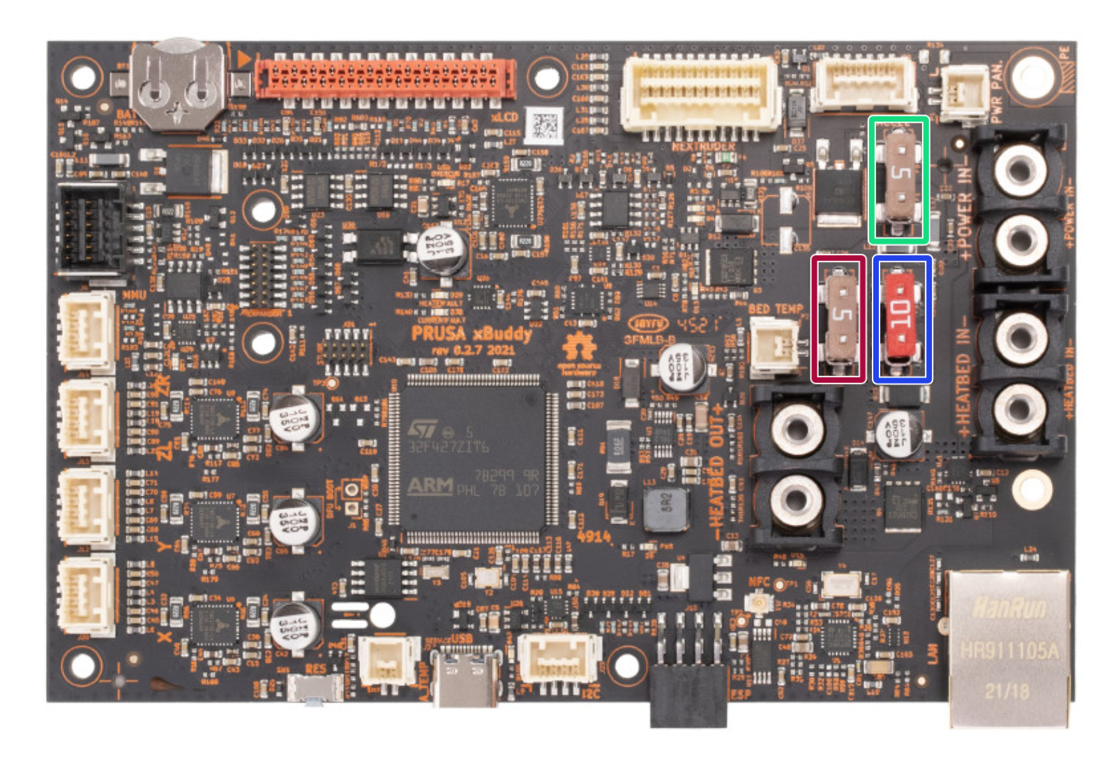
We could from this measure the ST32 chip, the ethernet connector, etc. I will see if I can find dimensions of the connectors too.

And no no don't be ashamed at all, this is really good, thank you very much! The chamfer doesn't bother me much to be honest, I prefer this than potential conflicts with the end cap. However, yes I agree with you that we might need to hold this part from the side.

Also I think we can get some space at the bottom with the motor mount by lowering the motor a little, 2-3mm. For this we could make the motor mount thicker and make a U shape opening to be able to slide the motor inside. We will loose the self centering feature of the motor unfortunately.

PatB42 commented 1 year ago

Wo excellent this pic , didn't saw on prusa, but yes that should be good to get the size as the USB port it's also good start.. to find it . now i wonder me what is the benefit to use the metal box for this xbuddy ! 1 french user told me it's perfect fit and arranged inside all cable not 1mm too much !!

thanks for ur feedback Greg abt the loadcell it makes me feel better great...:-((((( ...

gregsaun commented 1 year ago

@PatB42 The metal box has many advantages and I actually wanted to make one. The advantages are:

For the dimensions, the ST32 is an LQFP144 package of 20x20mm (+/- 0.2mm). Here are the sizes: Screenshot_20230617-125233 Screenshot_20230617-125329

lps-rocks commented 1 year ago

@PatB42 The metal box has many advantages and I actually wanted to make one. The advantages are:

* shield against the environment

* can use it to cool down the stepper and MOSFET

* more durable

* no long print time

For the dimensions, the ST32 is an LQFP144 package of 20x20mm (+/- 0.2mm). Here are the sizes: Screenshot_20230617-125233 Screenshot_20230617-125329

Easiest thing here would be to re-use the existing box that comes with the upgrade / MK4 kit. There are contact pads that are stamped into the box for cooling the stepper drivers + power regulator.

PatB42 commented 1 year ago

Well that nice but in fact IF the metal box better even for me it's not big improvement but never mind its shipping with the 3.9kit that what i was reading. then the idea is how to fix the metal box on the alu profil !! sad that there is no door but 4 screws !! if u want open it fast then forget..:-(

akbiocca commented 1 year ago

Since even the 3.5 upgrade kit replaces the electronics the metal box would be needed there also. All upgrade paths should include it, I would expect.

On Tue, Jun 20, 2023 at 3:05 AM PatB42 @.***> wrote:

Well that nice but in fact IF the metal box better even for me it's not big improvement but never mind its shipping with the 3.9kit that what i was reading. then the idea is how to fix the metal box on the alu profil !! sad that there is no door but 4 screws !! if u want open it fast then forget..:-(

— Reply to this email directly, view it on GitHub https://github.com/gregsaun/prusa_i3_bear_upgrade/issues/138#issuecomment-1598486875, or unsubscribe https://github.com/notifications/unsubscribe-auth/A3AIDK7TWSR3FCEHOTKQJPTXMFYVBANCNFSM6AAAAAAWM2Y2GI . You are receiving this because you were mentioned.Message ID: @.***>

gregsaun commented 1 year ago

@PatB42 yes sure it is better to reuse the metal cover. And agree with @akbiocca , it should come with 3.5 upgrade as well

ByJuix commented 1 year ago

Hey there, I plan to modify the Nextruder to allow a Slice Engineering Mosquito hotend to be mounted. I'm sure it'll be a bit of a challenge :D

TLDR: I would appreciate it if somebody with a MK4 could try to attach some weight to the extruder and see if the first layer calibration succeeds. @akbiocca maybe?


I own a Prusa MK3S+ Bear and would like to keep my Mosquito hotend. I ordered the MK4 upgrade kit, but I think it won't ship within the next two weeks; therefore, it would be good to know if the first layer calibration still succeeds if there is added weight on the extruder assembly. The Mosquito is roughly 10g to 15g heavier than the stock Nextruder heatblock; also there are other printed parts needed, in total it will be around 20g to 30g heavier.

To make this work, the Mosquito will be mounted on top of the loadcell and the gearbox and motor have to be inverted to stick out the front so that the filament can be fed into the heatbreak, that whole construction then has to be turned so that the nozzle can be aligned with the regular position.

Is it worth the hassle? Probably not, but it would be cool to know if it's possible and maybe @BondtechAB can design a better solution.

akbiocca commented 1 year ago

I'm not going to be able to do this with my current schedule, sorry.

On Wed, Jun 21, 2023 at 1:35 PM Julian @.***> wrote:

Hey there, I plan to modify the Nextruder to allow a Slice Engineering Mosquito hotend to be mounted. I'm sure it'll be a bit of a challenge :D

TLDR: I would appreciate it if somebody with a MK4 could try to attach some weight to the extruder and see if the first layer calibration succeeds. @akbiocca https://github.com/akbiocca maybe?

I own a Prusa MK3S+ Bear and would like to keep my Mosquito hotend. I ordered the MK4 upgrade kit, but I think it won't ship within the next two weeks; therefore, it would be good to know if the first layer calibration still succeeds if there is added weight on the extruder assembly. The Mosquito is roughly 10g to 15g heavier than the stock Nextruder heatblock; also there are other printed parts needed, in total it will be around 20g to 30g heavier.

To make this work, the Mosquito will be mounted on top of the loadcell and the gearbox and motor have to be inverted to stick out the front so that the filament can be fed into the heatbreak, that whole construction then has to be turned so that the nozzle can be aligned with the regular position.

Is it worth the hassle? Probably not, but it would be cool to know if it's possible and maybe @BondtechAB https://github.com/BondtechAB can design a better solution.

— Reply to this email directly, view it on GitHub https://github.com/gregsaun/prusa_i3_bear_upgrade/issues/138#issuecomment-1601633566, or unsubscribe https://github.com/notifications/unsubscribe-auth/A3AIDK3WP5MHNL5BA22DOULXMNLIFANCNFSM6AAAAAAWM2Y2GI . You are receiving this because you were mentioned.Message ID: @.***>

gregsaun commented 1 year ago

@ByJuix I think this will be very hard to make it working. Loadcell is only one of the problem you may have. Some other features I see today that might block you: filament sensor, second thermistor in the heatsink, thermal model calibration. If you really want to use Mosquito then stick to MK3S and wait for my new extruder to come out (made for Revo only but CAD files will be available).

akbiocca commented 1 year ago

The Mosquito hotend is very wide, and the new Prusa Nextruder hotend is very compact and very integrated into the loadcell system. On the Vorons there have been problems with the Mosquito's size even before their business practices led to their being dropped from Voron support. I decided to use my Mosquito on the Railcore where there is room and good support for it. The Revo is very nice too, and in many ways the Nextruder hotend is like a Revo with options to use V6 or Nextruder nozzles. The one downside of the Revo is the lack of ability to use the V6 nozzles at all. The Nextruder hotend is quite the interesting compromise.

On Thu, Jun 22, 2023 at 4:43 AM Grégoire Saunier @.***> wrote:

@ByJuix https://github.com/ByJuix I think this will be very hard to make it working. Loadcell is only one of the problem you may have. Some other features I see today that might block you: filament sensor, second thermistor in the heatsink, thermal model calibration. If you really want to use Mosquito then stick to MK3S and wait for my new extruder to come out (made for Revo only but CAD files will be available).

— Reply to this email directly, view it on GitHub https://github.com/gregsaun/prusa_i3_bear_upgrade/issues/138#issuecomment-1602492315, or unsubscribe https://github.com/notifications/unsubscribe-auth/A3AIDK4RX2POWYSFLEJI2MDXMQVUZANCNFSM6AAAAAAWM2Y2GI . You are receiving this because you were mentioned.Message ID: @.***>

ByJuix commented 1 year ago

Thanks for the feedback. I created a quick sketch to visualize my idea, I think there are some misconceptions.

The red part represents the loadcell, the gray part the fan. I'm not certain how to mount the mosquito, but I think I will get some ideas within the next couple of days. [The nozzles are at the exact same location] nexquito nextruder

@gregsaun the other extruder parts you listed won't be a big problem, as the hotend will still be mounted to the loadcell; therefore the thermistor is still used like it should be. @akbiocca the size isn't a problem at all, the Mosquito is shorter and narrower than the loadcell. I'm pretty sure I can make it work.

gregsaun commented 1 year ago

@ByJuix Good luck and I am curious to follow how this goes. Might be better to share this in another place if that works for you, this thread is already quite long.

DesC21 commented 1 year ago

I just released the first version of Bear MK4 parts. https://www.printables.com/model/502515-prusa-i3-bear-upgrade-for-mk4

If anyone is brave enough to try, please leave some feedback either on printables or here. My MK4 kit takes at least 1-2 weeks to get here, I guess :).

PatB42 commented 1 year ago

Waou great job DEsc just look at ur files, excellent work..am sure it'll fit did u have the f3d files ? to check if i can adjust with my extruder cablecover as i did one and use chain system..thx

DesC21 commented 1 year ago

Waou great job DEsc just look at ur files, excellent work..am sure it'll fit did u have the f3d files ? to check if i can adjust with my extruder cablecover as i did one and use chain system..thx

thanks :-)! I actually forgot to add the source files or at least the step files. I'll add them in the next few days, because I am super busy at the moment.

jerem2st commented 1 year ago

J'attend cette mise à jour avec impatience les gars ! Quel beau travail parcouru jusque là avec le peu de donnée Prusa.. bravo :) Je suis l'avancement au jour le jour en espérant pouvoir bientôt passer à la MK4 Bear :)

PatB42 commented 1 year ago

@DesC21 thx no hurry ...all files would be fine.. some asking the F3d files or step files for the whole mk4 are they are not on the github !!! not fare... if we want to print on our own....but still waiting..

gregsaun commented 1 year ago

@DesC21 Great work, thank you very much! Thanks for the appropriate credits and license too ❤️ . May I ask you to publish the source files (F3D) as neither STEP nor STL nor 3MF are source, thanks in advance :) . Once done I'll make some noise for your work!

DesC21 commented 1 year ago

@gregsaun thank you very much. In good old Prusa fashion it took me a bit longer to post the source files sorry, I just wanted to get it out as soon as the kits started to ship. I just uploaded the source files on printables @PatB42.

Just a general quick update for everybody Prusa pushed new R2 and R3 files. Apparently the xLCD parts and maybe even PCB changed. My parts currently only work with the R1 and R2 parts, I think. So just a heads up, the current kits ship with R3 and my bear parts need some changes. I'll try to do it as fast as possible but this project takes more time than I imagined :-)....

I will get my kit hopefully next week so there should be confirmation soon if the parts work or not :-).

@gregsaun I got feedback on printables that the holes for the z-rods are to tight. I kept the tolerances from your design and from what I found online these should also work fine for the 10mm rods. Maybe the tolerance from the prusa z-rods is not as good as previously? Any idea Greg? Maybe it's just that the printer was not well calibrated, we'll see when I get my kit...

PatB42 commented 1 year ago

I just uploaded the source files on printables @PatB42. ths so much Desc21 , i'll have a look and let u know my input but am sure it's great job and fit well..If Jo modifiy the part every week we'll die ;-)))

gregsaun commented 1 year ago

@DesC21 Thanks for the source files, I appreciate 👍 . Yes parts are now R2 and R3 for almost everything, make sure to check all the parts you have updated. We might see quick changes in the beginning but it will slow down after. For the Z rods I doubt it is the rod tolerance as those are still a lot more precise than our parts, I would first confirm with the user that he did calibrate extrusion multiplier and use PETG. A better way than the slot like Prusa does is to make an hexagonal hole, like this if too tight the rod will compress the plastic more easily than if it is a full circle

n4bft commented 1 year ago

This has come out quite well with all of the designing being purely in CAD and with no practical test bench yet. So Kudos to you @DesC21 for your work.

The biggest issue I've been running into is the width of the X axis has changed and Prusa is using a new frame, however they have yet to publish the STEP/STL of the frame so I can't validate my changes. So far I've had to add 2mm of width between the Z-motor mounts and z-tops, which makes sense, given the additional 1mm of radius per rod. (I think this will be the right number, the next set of z-motor mounts are printing now). I confirmed my bear v2.1 kit extrusions are all the right lengths and the frame is square (within an unperceivable error). The X axis fits perfectly on my MK4, so it's not the X-axis itself, therefore leaves just the Z-motor mounts as the culprit.

The only other item that may be an issue is Prusa added a rubber pad between the motor and the z-motor mounts, which may adjust the z-motor screw length by 2mm, so more changes may be needed on the z-tops.

@DesC21 Thanks for the source files, I appreciate 👍 . Yes parts are now R2 and R3 for almost everything, make sure to check all the parts you have updated. We might see quick changes in the beginning but it will slow down after. For the Z rods I doubt it is the rod tolerance as those are still a lot more precise than our parts, I would first confirm with the user that he did calibrate extrusion multiplier and use PETG. A better way than the slot like Prusa does is to make an hexagonal hole, like this if too tight the rod will compress the plastic more easily than if it is a full circle

My printer is calibrated properly. I'm running into this on an MK3 and MK4, I added a cut to give the slicer a place to put the seam. It seems the new perimeter generator used in PrusaSlicer tends to leave a more prominent seam than the classic perimeter generator (at least in my experience).

@gregsaun thank you very much. In good old Prusa fashion it took me a bit longer to post the source files sorry, I just wanted to get it out as soon as the kits started to ship. I just uploaded the source files on printables @PatB42.

Just a general quick update for everybody Prusa pushed new R2 and R3 files. Apparently the xLCD parts and maybe even PCB changed. My parts currently only work with the R1 and R2 parts, I think. So just a heads up, the current kits ship with R3 and my bear parts need some changes. I'll try to do it as fast as possible but this project takes more time than I imagined :-)....

I will get my kit hopefully next week so there should be confirmation soon if the parts work or not :-).

@gregsaun I got feedback on printables that the holes for the z-rods are to tight. I kept the tolerances from your design and from what I found online these should also work fine for the 10mm rods. Maybe the tolerance from the prusa z-rods is not as good as previously? Any idea Greg? Maybe it's just that the printer was not well calibrated, we'll see when I get my kit...

Prusa has finally been publishing the STLs of the parts they've been shipping in kits for weeks. So these changes are weeks old. So far, I haven't found any breaking changes in regard to geometry changes of the printer, I believe most of the changes are for strength, hardware tolerances, or ease of printing.

DesC21 commented 1 year ago

@n4bft

thank you very much!

For the z-parts are you talking about my parts with adding additional space to the width? I finally got my kit yesterday, so I can try and test this myself. So far the z-axis is based on the R1 parts and as far as I can see there are no changes for the R2/R3 parts in width. So I would guess my parts would fit since the CAD assembly works but I can't confirm yet. There was a comment on printables about the width not being correct, but it was deleted before I could get to it.

Just to make sure, are you HeXXy from printables? Sounds like it from the rod problem?

@DesC21 Thanks for the source files, I appreciate 👍 . Yes parts are now R2 and R3 for almost everything, make sure to check all the parts you have updated. We might see quick changes in the beginning but it will slow down after. For the Z rods I doubt it is the rod tolerance as those are still a lot more precise than our parts, I would first confirm with the user that he did calibrate extrusion multiplier and use PETG. A better way than the slot like Prusa does is to make an hexagonal hole, like this if too tight the rod will compress the plastic more easily than if it is a full circle

duhh, of course the tolerances of the rods are so much better.... The hot weather is getting to my head I guess :-)

PatB42 commented 1 year ago

The hot weather is getting to my head I guess :-) ...;ahha use ur fridg !! hehe my concern now is about FMW , i read Greg said there was a secret menu that allowed to use for the bear frame ? or can we use the 3.10bear fmw then back to stock prusa fmw? i should receive my kit next month too..