 mithro
commented
3 years ago
mithro
commented
3 years ago /cc @kgugala @pgielda @mgielda
Open umarcor opened 3 years ago
mithro
commented
3 years ago /cc @kgugala @pgielda @mgielda
 j0ono0
commented
3 years ago
j0ono0
commented
3 years ago I haven't cracked the issue of easy and good hardware images yet - I've been semi-manually creating them so far - exporting tracks from kicad then manually create the image. Do you have boards documented online? I'd be interested to browse through some more real-world projects and revisit this aspect of diagram creation and styling.
 olofk
commented
3 years ago
olofk
commented
3 years ago I like this a lot. There are a number of other things I have been considering too, like adding links from LibreCores projects to which boards they support, having language-agnostic pin constraints (unifying this kind of info from source like litex and other places).
 umarcor
commented
3 years ago
umarcor
commented
3 years ago I haven't cracked the issue of easy and good hardware images yet - I've been semi-manually creating them so far - exporting tracks from kicad then manually create the image.
@j0ono0 I believe everything is to be done yet. AFAIAA all cool and nice pinout diagrams are created manually, which is very painful. Therefore, any semi-automatic solution would be very helpful. I like how the KiCAD approach sounds, however, I don't think that exporting tracks is necessary for pinout diagrams or interactive co-simulations. I like the second demo in your readme (https://raw.githubusercontent.com/j0ono0/pinout/main/docs/_static/finished_sample_diagram.png) because it is clean, simple, but still contains the required info. So, I would suggest exporting the main holes, connectors and "large" chips on the board, but not all tracks, resistors and capacitors. Removing tracks should also help reduce the complexity of the SVGs.
Do you have boards documented online? I'd be interested to browse through some more real-world projects and revisit this aspect of diagram creation and styling.
That is one of the purposes of this repository, together with hdl/awesome. Here, there is a YAML file containing the info of each board. See the template (https://github.com/hdl/constraints/blob/main/template/board.info.yml) or any of the items in https://github.com/hdl/constraints/tree/main/board. Then, that info is processed with a Python script (https://github.com/hdl/awesome/blob/develop/constraints.py) to make it fit into the https://gohugo.io/ site (the static site generator used in hdl/awesome). Basically, the YAML is pasted as the frontmatter of a markdown file. The result is https://hdl.github.io/awesome/boards/. Images/photos are located in https://github.com/hdl/awesome/tree/develop/static/boards. The links/refs in each board will typically get you to the repo, where you can find sources and examples.
As you see, there is lots of room for improvement both in the frontend and in the template. It would be possible to display more info or filtering the content per vendor, FPGA type/model, available connectors, etc. We might show the "autogenerated" pinout next to the photos (for open source boards developed with KiCAD). In other sections of hdl/awesome, descriptions of items are shown: https://hdl.github.io/awesome/items/. We could add descriptions to the boards too. The main idea is to keep the board info/metadata in this repo, and to do the fancy visualization in hdl/awesome.
like adding links from LibreCores projects to which boards they support
@olofk, currently, there are no per-item pages for each board in https://hdl.github.io/awesome/boards/. Instead, they point to a subdir in this repo. However, we might add those individual pages, so that LibreCores labels/tags point to them. Alternatively, LibreCores might pick the list/info from this repo, without using hdl/awesome.
having language-agnostic pin constraints (unifying this kind of info from source like litex and other places).
This was/is the very main purpose of this repository. Please, see https://hdl.github.io/constraints/ and https://hdl.github.io/constraints/#_litex_hublitex_boards.
umarcor
commented
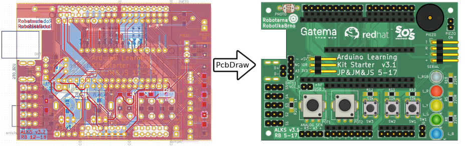
3 years ago yaqwsx/PcbDraw looks really interesting for creating the drawings to then add pinout info with j0ono0/pinout, or for using them in interactive co-simulation frontends.
Convert your KiCAD boards into nice looking 2D drawings suitable for pinout diagrams. Never draw them manually again!
PcbDraw also comes with a small utility called Populate which allows you to easily specify & maintain nice looking HTML or Markdown population manuals.
/cc @yaqwsx
j0ono0
commented
3 years ago I'll have to try it out - initial browse looks like a good option. Thanks for posting!
umarcor
commented
3 years ago I updated the theme in hdl/awesome and the info.yml/README.md files in the subdirs of board in this repository. Now the items in hdl.github.io/awesome/boards point to a page for each board. For example: hdl.github.io/awesome/boards/ac701.
I'd like to propose using Fomu PVT and/or iCEBreaker Bitsy v1.1b as an example to try combining the projects mentioned in this thread.
/cc @esden @smunaut
j0ono0
commented
3 years ago Sure can. Any specific specs it should ideally match? The existing pinout diagram looks like it was laid out for print at A5 size (similar to the teensy pinout card). Might be nice to match the max screen width of github (1012px wide). It would take up more screen real-estate but make a more usable on-screen reference for users.
umarcor
commented
3 years ago @j0ono0 I have no preference at all with regard to size or style. I'm mostly interested in having an "automated" solution as a result of several users/projects collaborating.
I agree that a width of 1000-1280 px and a 16:9 aspect-ratio would be nice for screens. However, people from the iCEBreaker project might want to actually print it using A5, as you suggested, and give it with the boards. Nonetheless, once any of them exists, I guess it would be trivial to adapt it for a different layout.
Anyway, you might want to start with Fomu. I didn't provide an explicit reference, but you can find it in https://workshop.fomu.im/en/latest/requirements/hardware.html:
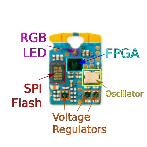
The four contacts at the top are one I/O each, and the others are the USB. Apart from that, there is an RGB LED. There is no more I/O.
Strictly, some of the test-points on the PCB can be used for programming the SPI flash, in case the bootloader dies (https://raw.githubusercontent.com/im-tomu/fomu-hardware/master/archive/pvt/releases/pvt1/tomu-fpga-pvt1.pdf). However, I would say those are out of scope for most Fomu users, so no need to include them in the pinout yet.
j0ono0
commented
3 years ago FOMU looks MUCH easier than the Bitsy. I'll add that to my queue for boards to try out.
I actually had a go creating a pinout for the iCEBreaker Bitsy. Definitely a complex board to document due to the various in-board pin locations. Current solution has been to split out board sections for documentation. I've got a few more challenges to resolve with it and will post progress once I have a finished basic version.
j0ono0
commented
3 years ago Can anyone field a few questions about the Bitsy pinout? I'm seeing on the existing pinout names with underscores in them. To my untrained eye some of these entries looks suspiciously like multiple name/function notes divided with underscores. I'm wondering if breaking them on the underscores into separate labels (or represent aspects as colour/pattern) would be accurate documentation?
for example: existing FPGA Pin Name: IOB_35b_SPI_CSN
does that actually break down to: pin name: IOB_35b (is the name actually '35b' and the prefix some additional group ref?) protocol interface: SPI pin function: CSN
 smunaut
commented
3 years ago
smunaut
commented
3 years ago IOB_35B is the IO site corresponding to that pad. 'IOBmeans 'Bottom IO bank. 35 is the site number and B (vs A) is because some pins are grouped by two in each IO tile. (However even when grouped, they will have a number. grouped pins are consecutive number but sometimes the A is before or B is before, it's not consistent, you need to check the docs to know)
SPI_CSn is because this is a special purpose pad that's used during configuration. It's the pin the FPGA will use to select the flash at bootup and then after config, it becomes a normal user IO.
j0ono0
commented
3 years ago thanks for the info @smunaut. I'm feeling slightly less clueless! I'm still pondering whether I could remove the "IOB/IOT" text and represent it graphically to remove some visual clutter - I've tried this approach with the SPI and USB labels.
A nice "work in progress" picture to finish my day. Still a lot of details I think can be revised to make a more efficient example. Most note worthy detail - label data is pulled from a google spreadsheet. https://github.com/j0ono0/icebreaker/blob/pinout/hardware/bitsy-v1.1b/pinout/pinout_wip_bitsy-v1.1b.svg
mithro
commented
3 years ago @j0ono0 - If you don't have Fomu / Qomu / Somu / Tomu hardware, I would be more than happy to send you some! (Email me an address + phone number to me@mith.ro)
j0ono0
commented
3 years ago Some progress!

Files are here -- https://github.com/j0ono0/tomu_pinout -- although I want to do some rework sessions to tidy things up. General goal has been to create a some-what flexible template that is populated by user supplied data. Data source is currently a python file but could easily be a spreadsheet (I got a demo of that in the works too.)
EDIT: An initial review and refactoring complete. the repo now features 'template.py' which is an attempt to provide a prescriptive approach to layout - this de-clutters the code substantially. 'pinout_diagram.py' and 'data.py' now show a clearer selection of what data might be automated and what will need manual decisions.
if images could be generated along with coordinates of pins and components a good amount of content could still be automated.
umarcor
commented
3 years ago the repo now features 'template.py' which is an attempt to provide a prescriptive approach to layout - this de-clutters the code substantially. 'pinout_diagram.py' and 'data.py' now show a clearer selection of what data might be automated and what will need manual decisions.
Congrats @j0ono0! Those (both bitsy and Fomu) look so nice and the "configuration" files are much easier to read 😃
I had a look at the tomu_pinout repo. The content of data.py has some similarities and differences compared to a possible YAML representation of the constraints (PCF files) in this repo. See, for instance, https://github.com/hdl/constraints/tree/main/board/Fomu-PVT and https://github.com/umarcor/hwstudio/blob/main/data/boards/fomu.yml.
It would be interesting to have the content cross-referenced. I don't think we want to put the locations and size in the YAML, and we don't want to put the mode and other instantiation/implementation info in data.py. I see two options:
The issue I see with the first approach is the grouped items in fomu_pinlabels. There, labels is a list of lists containing tuples. My intuitions says that it would be possible to add an item to the tuple, but I'm unsure.
Similarly, the issue with the second approach is how to reference the items which are grouped in fomu_pinlabels. However, I think we might use name:label, where label is the first item of the tuple.
What do you think? Is it worth having a reference in your data format or should we handle it here?
Having those cross-references should allow us to generate multiple variants of the diagram. In your example above, names are shown only. We could show the pin numbers, the HDL names and/or the three "identifiers" at the same time. Note that it would not require modifications on pinout (the tool), since we can handle those variations from data.py alone.
Yet, I believe it will not be useful to show all the information in the diagram at the same time. However, since we can read the YAML in Python and combine it with the data.py, we can use tabulate for printing the detailed info as a table. Tabulate supports ~20 output formats (including "plain", "github", "rst", "latex"...). Hence, we are so close from having a solution that users can include in the Sphinx/Hugo/Jekyll documentation of their projects.
Data source is currently a python file but could easily be a spreadsheet (I got a demo of that in the works too.)
Once it is stable, it would be useful to document the format of the Python file. That will make it easy for anyone to use any file format: CSV, JSON, YAML, etc. I.e., I don't think you need to implement the "readers" yourself, but just help contributors prepare the data for you. One of the great advantages of Python is precisely the flexibility for dealing with many different file formats, lists and dictionaries.
if images could be generated along with coordinates of pins and components a good amount of content could still be automated.
For KiCAD projects, I think that Pinion can extract that info:
https://yaqwsx.github.io/Pinion/diagramWalkthrough.html
pinion generate \
   --board <path to .kicad_pcb file> \
   --specification <your YAML file> \
   <path to output directory>
Nonetheless, I believe it's acceptable for the data.py file in pinout to require that info. There is no need to build the pin info extraction feature into pinout.
j0ono0
commented
3 years ago The content of PCF, YML, and Pinion YAML files are similar to data.py. My work-in-progress PCIe spreadsheet also approximates columns to those PCF file titles - feels tantalizingly possible to pull it all together.
I've only had a brief look at Pinion and KiCad files - I'll have to look into these in more depth. Pinion can clearly fill a big prerequisite with image creation and feature location.
umarcor
commented
2 years ago Ref: pinouts.org
j0ono0
commented
2 years ago quick update for the record: I've had a few attempts at getting Pinion to work in Windows 11 but with no success. It appears the Windows version of KiCad is not quite up to the task yet. I'm yet to try with recently released KiCad v6 or WLS2 etc.
Current work/experiments are on a related aspect: Annotating pin-out data in KiCad, then generating a pinout diagram from the KiCad file (progress is promising so far).
 yaqwsx
commented
2 years ago
yaqwsx
commented
2 years ago @j0ono0: Pinion should work on Windows with KiCAD 6. Please, open an issue for that with precise steps to reproduce the problem.
PS: First thing you should try is to invoke everything (including installation) from "KiCAD command prompt". It ensures you use the correct python binary. However, when I wrote installation instructions for Pinion, it was not available in nightly yet.
j0ono0
commented
2 years ago Thanks @yaqwsx, I'll make some time to update kicad and give it another go. I don't recall using the kicad command prompt so that may be the key.
j0ono0
commented
2 years ago whoo-hoo success! Thanks @yaqwsx. Installing via KiCad command prompt on v6 worked smoothly. Either I overlooked your windows install docs or you've updated them since my last attempt - They were very clear and easy to follow.
It would be nice to use j0ono0/pinout for generating homogeneous pinout diagrams of the boards. However, it requires an image of the board, where labels and pin names are ovarlaid. In this regard, it is similar to the verilatio prototype in https://twitter.com/OlofKindgren/status/1365755881766465543 or the virtual board in https://gitlab.ensta-bretagne.fr/bollenth/ghdl-vpi-virtual-board. Therefore, it would be interesting to gather either photos or SVG diagrams of the boards, which can then be used for generating pinout cheatsheets, interactive co-simulations, etc.
/cc @j0ono0 @olofk @timonsku @mithro