hugen79 / NanoVNA-H

NanoVNA-H based on edy555 design, provides effective measurements up to 1.5GHz.
http://nanovna.com/
515 stars 124 forks source link

(Fixed) Hardware mods to get fixed the loss of dynamic of CH1 in the harmonics mode #40

Open Pmax65 opened 4 years ago

Pmax65 commented 4 years ago

Hi Hugen, here I publish my mods to almost completely fix the loss of dynamic above 300MHz when the DUT is a LPF tuned below but closed to 300MHz such as VHF/UHF duplexers. The mods on my prototype still have a little loss of dynamic, but make the instrument useful. Here are the graph before and after the "cure". Before: Test 300kHz-600MHz After: Test 300kHz-600MHz RFsw

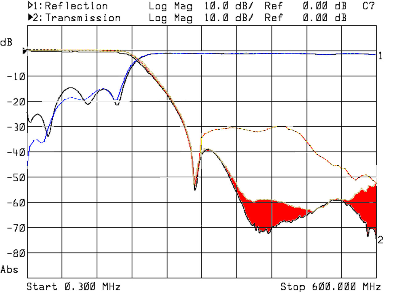
The red areas are the remaining dynamic losses. Above 600MHz I never see any substantial dynamic loss. The schematics are the followings. With added 8MHz oscillator for the MCU & DSP: HPF 300MHz Elliptic 5th Order with Switch With 2 RF switches: HPF 300MHz Elliptic 5th Order with 2 Switch The two solutions are because it has been easier for me to use the inner output power amplifiers enable signal of the Si5351A instead to add an another RF switch (the size of nanoVNA have been a great constraint for fit the prototype PCBs there). This photo explains all: IMG_20200321_165004 Anyways, the single RF switch version gives the advantage of a stable clock to the MCU & DSP. This because the "arrhythmia" that I seen in the MCLK (that I was believing due to the noises around), it was instead due to the clock interruptions during the band switching. The only reason the system doesn't locks, it's that the inner PLLs of both the chips still produce a clock, even if on a very different frequency. The contra of the single RF switch solution is that I had to modify the Si5351A settings to get the DUT test frequency from output 1 for frequencies below 300MHz and from output 2 for the frequencies above. This implies that the firmware is no longer compatible with the older hardware setup. I used the scan LED2 signal (U4-2) to drive the 5th order high pass elliptic filter, but my choice is due just because it was the easiest solution to get a sufficient wide pad to solder the switch(es) control wire in the nanoVNA PCB. For the firmware development, the U4-2 signal must be set active at 3.3V for the odd harmonics mode and must be set deactive at 0V for the fundamental mode.

I also changed the CH1 front-end configuration as follows: R22 = 68 ohm 0603 1% resistor R23 = 0ohm 0603 shunt R24 = 120ohm 0603 1% resistor R25 = 22ohm Note that it has changed form differential to single ended, just because it was a nonsense. The driving signal of the SA612D mixer was in-phase on both sides of R25, so there was no advantages using that configuration. I found this configuration less noisy indeed and best matching the CH1 input port impedance for higher frequencies, that thanks to the higher value of R22 that is the one which influence more the capacitive behaviour of the CH1 input port trought the mixer input capacitance.

By the way, I found a strange stream of pulses on the LED2, which is produced by the macro PULSE into nanoVNA.h and used by function draw_cell() into plot.c. I think it was some checking signal used during debug that I think it should be removed.

I thought to publish this mod procedure for those who desire to modify their current or the older versions of nanoVNA, but the complexity of it suggested me to avoid it. I had to use a thin SR-047 coaxial line to connect the filter which involves a certain skilness to do it.

Hope this will help you for your next production batch.

Have a great day.

Massimo

hugen79 commented 4 years ago

Hi Pmax65, thank you very much for your suggestion. This modification seems to be difficult to install 2.8 inch nanovna-H, but it can be very convenient to install NanoVNA-H4 with a larger PCB area. I will start my test.

hugen

hugen79 commented 4 years ago

For the impedance of CH1, it seems that it is affected by the parasitic capacitance on the PCB. After you change to single-ended, you reduce the length of the signal line and reduce the parasitic capacitance. I modified it in nanoVNA-H 4 by reducing R24 and reducing the effect of parasitic capacitance of the circuit behind R22 and R23. In the next improvement I will try to increase the distance between the signal line and copper to reduce parasitic capacitance. hugen

Pmax65 commented 4 years ago

Hi Hugen, I don't agree with this:

For the impedance of CH1, it seems that it is affected by the parasitic capacitance on the PCB. After you change to single-ended, you reduce the length of the signal line and reduce the parasitic capacitance.

Even if surely the parasitic capacitance of the PCB should matter above 1GHz, I did the mod placing a 0ohm resistor for R23, so the parasitic capacitance remained the same. What it changed is the greater pure resistive value of R22, which being in series to the input mixer capacitance reduced the influence of this input capacitance on the CH1 input.

So I believe that you should make that input single-ended not differential that has no advantage anyways.

Have a great day. Massimo

Pmax65 commented 4 years ago

about:

This modification seems to be difficult to install 2.8 inch nanovna-H, but it can be very convenient to install NanoVNA-H4 with a larger PCB area. I will start my test.

I agree, I don't know if moving U6 and its passive components forward the SMA border could free sufficient space for placing the filter and even one RF switch only.

hugen79 commented 4 years ago

Hi Hugen, I don't agree with this:

For the impedance of CH1, it seems that it is affected by the parasitic capacitance on the PCB. After you change to single-ended, you reduce the length of the signal line and reduce the parasitic capacitance.

Even if surely the parasitic capacitance of the PCB should matter above 1GHz, I did the mod placing a 0ohm resistor for R23, so the parasitic capacitance remained the same. What it changed is the greater pure resistive value of R22, which being in series to the input mixer capacitance reduced the influence of this input capacitance on the CH1 input.

So I believe that you should make that input single-ended not differential that has no advantage anyways.

Have a great day. Massimo

Yes, single-ended allows an input pin to be directly grounded. The input capacitance of this pin is much larger than the parasitic capacitance. I will try your suggestion. Also because the current ch0 output is as high as 0dBm, we have to add 35dB attenuation in ch1 to keep sa612a linear, perhaps we can use iAM81008 with a higher 1dB compression instead, but the IAM81008 output impedance is lower, I don't know how easy to connect to the codec with high input impedance, which requires further trying.

hugen

Pmax65 commented 4 years ago

I Hugen, I didn't see any non linearity on the CH1, I used a 0-110dB 1dB/step attenuator and I honestly checked at 10dB/step and then I tried the first 10dB at 1dB without appreciable non-linearity. I see a little non linearity at the end of the bands at around -30dBm return loss instead. I don't see it below -40dBm (theoretical of course, just corrected by the calibration with that very same DUT)

I'm not sure you already read this: https://github.com/hugen79/NanoVNA-H/issues/39#issuecomment-599795538

That's the way to fix the discontinuities at the band change due to wrong interpolation around those band change points. I implemented a very simple extrapolation algorithm that it works.

Have a great day.

Massimo

hugen79 commented 4 years ago

I Hugen, I didn't see any non linearity on the CH1, I used a 0-110dB 1dB/step attenuator and I honestly checked at 10dB/step and then I tried the first 10dB at 1dB without appreciable non-linearity. I see a little non linearity at the end of the bands at around -30dBm return loss instead. I don't see it below -40dBm (theoretical of course, just corrected by the calibration with that very same DUT)

I'm not sure you already read this: #39 (comment)

That's the way to fix the discontinuities at the band change due to wrong interpolation around those band change points. I implemented a very simple extrapolation algorithm that it works.

Have a great day.

Massimo

Hi Massimo, I'm very sorry, it may be that my bad English didn't express my meaning correctly. I mean, currently our resistance between the sma port of CH1 and the RF IN of the SA612A provides 35dB of attenuation. If IAM-81008 is used, the attenuation resistance can be reduced to 15dB or even 10dB, which may obtain better measurement dynamics.

hugen

Pmax65 commented 4 years ago

Hi Massimo, I'm very sorry, it may be that my bad English didn't express my meaning correctly. I mean, currently our resistance between the sma port of CH1 and the RF IN of the SA612A provides 35dB of attenuation. If IAM-81008 is used, the attenuation resistance can be reduced to 15dB or even 10dB, which may obtain better measurement dynamics.

I fully agree

Pmax65 commented 4 years ago

Hi Hugen, since friends were interested in enhancing the dynamics above 300MHz when checking the low pass branch of a VHF/UHF duplexer, I finally designed a small 0.8mm thickness PCB for the filter mounting on the 2.8 inches nanoVNA-H.

Here is a photo of the PCB. IMG_20200601_163051

While here is the PCB mounted on the nanoVNA board. As you can see it's a little less tricky to mount than the prototype. IMG_20200601_163208

This is the new schematic, which give much more dynamic than the previous 5th order high pass filter, and practically the current noise still in the 300...400MHz range is due to the background noise crosstalk between CH0 and CH1. NanoVNAfilter

Here you can see the plots of the improvement. The red trace is the nanoVNA without any filter, while the green one is with the filter installed. As you can see the only noise excess is very tiny and due to the background noise there. The dark green areas are where nanoVNA is outperformed by the HP8711A, viceversa the light green areas are where nanoVNA outperformed the HP8711A. Test 300kHz-600MHz filtred

Here is the CH0 plot for the S11 parameter (note the jump at 300MHz due to the filter switching. CH0-S11 Here instead the CH1 plot for the S11 parameter CH1-S11

No changes done for the on board components respect to the previous 5th order filter version.

By the way, I simply connected the filter input and output using a wire-wrap short wires because the effects of their lengths should be compensated by the reference mixer. Instead, to avoid its resonating effect, I cut away the nanoVNA track from C12 and R13.

Have a great day.

Massimo

hugen79 commented 4 years ago

Hello Pmax65, it looks like your newly revised filter works very well. But I don't quite understand the role of R1 you added. The 24 ohm resistor will increase the insertion loss by 2dB.

hugen

Pmax65 commented 4 years ago

Hi Huigen. I placed that resistor to better match the filter output, and flatten the response in the 420-570MHz range which showed a 8dB flatness peak without it, anyways considering that the reference mixer picks the signal after it, it could be better to remove R1 indeed. I'll give a try, maybe it could gain some dB of dynamic above 1GHz.

Thank you.

Massimo - IK1IZA

Pmax65 commented 4 years ago

Hi Hugen, I checked it out and honestly I can't see any difference on the plots (up there those 2dB of dynamic improvement are probably hidden in the noise) and also the CH0 impedance is very little affected by that resistor. So, apparently there is no reason to get that resistor there. Have a great day.

Massimo

Pmax65 commented 4 years ago

Hi Hugen, I think this is my very last try for this issue since now it looks really great. Test 300kHz-600MHz filtered final

I just changed the wire-wrap with the SR-047 coax line because I noted a worsen of noise floor above 1.2 GHz in the last version (it had reduced to about 45dB at around 1.3GHz).. As you can see in the plot, other than returning the S21 dynamic of more than 50dB in the range 1-1.5GHz (not shown in the plot), thank to the coax lines the response improved a little more also in the 300-400MHz outperforming the HP8711A in that range now. In my opinion this improvement demonstrates that in case you want to embed this filter in your next instrument you should take care of the microstriplines because above 1GHz their wrong Z0 could compromise the instrument response.

07/06/2020 Edit: I investigated with HP8711A the resonance around540MHz and discovered that it is resonating point is very influenced by the tight of the DUT's connectors (it's an old Comet CF416 VHF/UHF duplexer, that use PL connectors for the VHF side and the antenna port). Doing this investigation I also noted that nanoVNA never outperforms the HP8711A because buried in the noise there is an another resonance around 430MHz that is influenced by the connectors tight too. This is visible changing the HP8711A bandwidth from the standard 3.7kHz to the narrower 250Hz. Anyways, in my opinion, with this modification nanoVNA does it very good for the S21 measurements.

Have a great day.

Massimo

hugen79 commented 4 years ago

I modified the schematic and added a high-pass filter, which should be the method with the lowest cost and least current consumption to improve the performance of the UHF band. But I am not sure if I will mass-produce the nanoVNA of the new circuit. Some users who need higher frequency applications are turning to SAA2. However, the traditional architecture of nanoVNA has faster speed and less current consumption. It should still have many hobbies need them. I am also trying to add an independent signal source for the 300-900M measurement, so that up to 900MHz has always been used for fundamental wave measurement, effectively improving the dynamics. If there is new progress, I will also release it in time.

Schematic_nanovna_2020-06-09_12-45-28

Pmax65 commented 4 years ago

Hi Hugen, it looks the you are doing great. I agree with you that you must follow you business needs. I just published the results to let you know that this way the dynamic is quiet good for this kind of instrument.

Have nice days.

Massimo

Pmax65 commented 4 years ago

Hi Hugen, just to inform you about that. I simulated your high pass filter setup and despite above 300MHz it is more flat than mine, it attenuates at least -40dB in the stop band while mine attenuates at least -70dB. I can't warrant you about the result on the S21 dynamic. I know that the switches have far less insulation between the ports, but they are two in series so that -70dB @ 1.5GHz are realistic indeed.

Have a nice day.

Massimo