Open xxxDrewedxxx opened 4 years ago
Greetings,
-What hardware connections do you have? adapter? which one? -Also, try your module as two 64x64 modules: led-chain=2, test without --led-panel-type=FM6126A, -This option: --led-slowdown-gpio=4 is for Raspberry Pi 3, or 4; start with --led-slowdown-gpio=1,2,3
Best regards
@daveythacher It looks like most of the chips are FM 6126B (RED) There are a column of RT5957DSP down the middle (BLUE) There are 3 74HC245C in a row running through the middle (YELLOW)
@davemaster -What hardware connections do you have? adapter? which one? RaspberryPi 4, ADAFRUIT RGB MATRIX BONNET FOR RASPBERRY PI, -Also, try your module as two 64x64 modules: led-chain=2, test without --led-panel-type=FM6126A, led-chain=2 ( and no --led-panel-type) gave me 4 dim "squares" instead of 2 bright
So GPIO 27 to ground on the bonnet? With the system running, or power down, jump between 27 and hound, and then boot with it that way? And remove the solder bridge that I installed on E to 8?
--led-row-addr-type=1 -> Black screen. No change with 27 and ground
yep
Ok, here is what I got. Yellow are when the ABC connect. A and B on U1 and C on U2 Red is the output(?) and where it connects to ALL UUX chips (1-8)
Sorry. Updated.
Blue and green go to all UUX chips.
Orange only seems to go to UU1
I hadn't gotten though all the multiplexing. Most of them just seem to make multiple of the same problem.
I've gone though all the multiplexing. None are any better. 7, 9, 15, and 16 are black screens for me.
Using this numbering
UU1 pin 10 goes to UU2 pin 2 UU2 pin 10 goes to UU3 pin 2 UU3 pin 10 goes to UU4 pin 2 U2 pin 12 goes to UU1 pin 2 only
Yes, UU4 pin 10 goes to UU5 pin 2, etc all the way through UU8
--led-row-addr-type=3 gives a black screen
Ok, You lost me there. How do I define the macro and recompile? Remove the # from line 40? then exit and save? I'm trying the row add type 3 and GIPO 27 long shot
Address type 3 gives black screen. GIPO makes no difference.
I'd like to explain that too, but I haven't a clue! It only lights up on address type = 0
Changed line 40. no difference. Didn't change line 160. Line 160 is uncommented but says "DEFINES+=$ (USER_DEFINES)
Ummm. I don't know. how would I check that?
0.024 volts as measured on the connector and on the panel This is the same voltage for address type zero
Whoops. I'm a moron. DC voltage setting works better. 4.89 vdc.
My power supply is 5VDC, 10 Amp
Sorry that was my bad. Had the meter set wrong.
--led-row-addr-type=3 4.98 VDC at the pins on the panel --led-row-addr-type=0 4.99 VDC at the pins on the panel
On type 3 logic I get about 0.78~ VDC on pins 16, 15, 14, 13, 5, 6, 7, and 8. on every UUx On Type 0 zogic I get : All reading are VDC. I think I'm going to hang it up for tonight. Thanks for your help today. I'll see what the morning brings us! | UU1 | UU2 | UU3 | UU4 | UU5 | UU6 | UU7 | UU8 |
---|---|---|---|---|---|---|---|---|
16 | 1.15 | 2.7 | 2.5 | 2.6 | 2.8 | 2.7 | 2.5 | 2.7 |
15 | 1 | 1.1 | 1 | 1 | 1 | 1 | 1 | 1 |
14 | 2.6 | 2.6 | 2.3 | 2.4 | 2.4 | 2.6 | 2.6 | 2.4 |
13 | 1.2 | 1.2 | 1.2 | 1.2 | 1.1 | 1 | 1 | 1 |
5 | 2.5 | 2.5 | 2.6 | 2.5 | 2.6 | 2.5 | 2.5 | 2.7 |
6 | 1.1 | 1 | 1 | 1.1 | 1.1 | 1 | 1 | 1.1 |
7 | 2.2 | 2.6 | 2.5 | 2.5 | 2.6 | 2.5 | 2.5 | 2.6 |
8 | 1 | 1.2 | 1.1 | 1.1 | 1.2 | 1 | 1.1 | 1 |
I ended up with: make[1]: [Makefile:185: framebuffer.o] Error 1 make[1]: Leaving directory '/home/pi/rpi-rgb-led-matrix/lib' make: [Makefile:15: lib/librgbmatrix.a] Error 2
~/rpi-rgb-led-matrix $ sudo examples-api-use/demo -D0 --led-rows=64 --led-cols=128 --led-gpio-mapping=adafruit-hat-pwm --led-brightness=60 --led-slowdown-gpio=4 --led-panel-type=FM6126A sudo: examples-api-use/demo: command not found
Whoops!
Well, crap. let me go git the files again.
Bonus! No errors when compiling this time.
Success!!!!
What caused the red screen?
Ran a different demo to check all lines active.
Tried the new code, got an error when recomplining.
make[1]: [Makefile:185: framebuffer.o] Error 1 make[1]: Leaving directory '/home/pi/rpi-rgb-led-matrix/lib' make: [Makefile:15: lib/librgbmatrix.a] Error 2
Possibly? I am using putty to access my pi. Is there an easy way to copy the whole thing? I might also be having a SD issue, ( it keeps dropping the network) so I started from scratch again. Give me a bit to reload and re-program
Hmm.. Still getting a error: make: *** [Makefile:183: framebuffer.o] Error 1
Here is the section of the file I edited: private: const int doublerows; const gpio_bits_t rowmask; const gpio_bitst clock; const gpio_bitst data; int lastrow; };
// Experimental! see issue #823 // An shift register row address setter that does not use B but C for the // data. Clock is inverted. class ABCShiftRegisterRowAddressSetter : public RowAddressSetter { public: ABCShiftRegisterRowAddressSetter(int double_rows, const HardwareMapping &h) : doublerows(double_rows), rowmask(h.a | h.b | h.c), clock(h.a), bk(h.b), data_(h.c), lastrow(-1) { } virtual gpio_bits_t need_bits() const { return rowmask; }
virtual void SetRowAddress(GPIO *io, int row) { io->SetBits(bk_); //Enable serial input for the shifter for (int activate = 0; activate < doublerows; ++activate) { io->ClearBits(clock_); if (activate == doublerows - 1 - row) { io->SetBits(data); } else { io->ClearBits(data); } io->SetBits(clock); } io->SetBits(clock); io->ClearBits(clock); io->ClearBits(bl); // Disable serial input to keep unwanted bits out of the shifters lastrow = row; }
private: const int doublerows; const gpio_bits_t rowmask; const gpio_bitst clock; const gpio_bitst data; const gpio_bitst bk; int lastrow; };
// The DirectABCDRowAddressSetter sets the address by one of // row pin ABCD for 32х16 matrix 1:4 multiplexing. The matrix has // 4 addressable rows. Row is selected by a low level on the // corresponding row address pin. Other row address pins must be in high level. // // Row addr| 0 | 1 | 2 | 3 // --------+---+---+---+--- // Line A | 0 | 1 | 1 | 1 // Line B | 1 | 0 | 1 | 1 // Line C | 1 | 1 | 0 | 1
Opps. I see I had a typo in there Fixed that, but now --led-row-addr-type=3 is black screen again.
and with a reboot it is back! SMDH!!!
OK, your new logic works. IT helps for me to type it in correctly and in the correct space.
Thank you for your help daveythacher! It has been running great!
- Deleted all Dir in the pi and started from scratch.
- After no change from before I changed the code in rpi-rgb-led-matrix/lib/framebuffer.cc as you stated
- Now it works with: sudo examples-api-use/demo -D0 --led-rows=64 --led-cols=128 --led-gpio-mapping=adafruit-hat-pwm --led-brightness=60 --led-slowdown-gpio=4 --led-panel-type=FM6126A --led-row-addr-type=3
I was having the same issue with this specific panel. Had to dig deep to find this. These parameters made it work, thank you so much!
@daveythacher Are you still around? I'm having this issue with another panel and all your comets have disappeared.
I am attempting to get a 128x64 p2.0 running off of an adafruit bonnet.
Using: sudo examples-api-use/demo -D0 --led-rows=64 --led-cols=128 --led-gpio-mapping=adafruit-hat-pwm --led-brightness=60 --led-slowdown-gpio=4 --led-panel-type=FM6126A --led-multiplexing=0 --led-scan-mode=0 --led-row-addr-type=0 led-chain=1 led-parallel=1
I get this:
If I change the --led-row-addr-type to anything but "0" I get a black screen. I have pad "E" on the bottom of the bonnet jumpered to "8"
Basically this, but missing every other row.
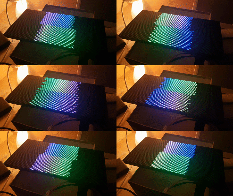
I really am over my head here, so please use small words! lol Thanks!