Closed marcmerlin closed 1 year ago
Previous discussions of the quirky fm6126A"
https://github.com/hzeller/rpi-rgb-led-matrix/issues/746
There is some code and comments regarding that chip, in this driver https://github.com/2dom/PxMatrix/blob/master/PxMatrix.h
http://ledpixelart.com/pixelv2board/ declares the FM6126A is not compatible with their setup.
One guy suggests that only init code must be added to solve his FM6126A problem: "I just ported this file so that it works on my rPi, ran it, and then plugged my Teensy with SmartMatrix code (unmodified), and things just worked. So this confirms that the only problem is indeed the init necessary with those FM6126A chips"
https://community.pixelmatix.com/t/smartmatrix-doesnt-support-fm6126a-driver-chips/421
@jake653 "One guy suggests that only init code must be added " => that was me :)
Sorry that my message was unclear, the problem is not FM6126A which is solved with the out of band init code (hopefully will get integrated in the lib proper soon), it's the ABC addressing. @hzeller can you confirm that ABC addressing is not currently supported by your lib (or any other lib I've seen actually)? I've only ever seen AB or ABCD or ABCDE
Sorry that my message was unclear, the problem is not FM6126A which is solved with the out of band init code (hopefully will get integrated in the lib proper soon), it's the ABC addressing.
I have ABC addressing panel using ICN2037, and I was not able to make it work.
If this is an FM61A but only has three address lines, would this probably be working with (the new flag) --led-panel-type=fm6126
and one of the --led-multiplexing options (because outdoor panels do different multiplexing).
My 64x128 panel is not fm6126, but ICN2037, and it has only ABC lines:
and this is how the demo with -D 3 looks like:
It is written on the panel: P2-128X64-32S-V4.0, LED1515, 2018/06/16
(I have other panels with HUB75E with ICN2037, and those working fine)
ABC sounds like a different led multiplexing. Did you try through the available --led-multuplexing
options?
Yes, I tried them, none of them worked.
This is how demo 0 looks like:
sudo ./demo --led-cols=128 --led-rows=64 --led-slowdown-gpio=5 -D 0
It seems for the half of the panel, it repeats 4 line, and the other half, it repeats another 4 line.
ABC could also means some different row address type; there are a few implemented, but they don't do three address lines. It might be worthwhile doing some reverse engineering, then implement this.
It looks a bit like the AB row address type but maybe split into top and bottom half ? So I would try with --led-row-addr-type=1
and see if that at least gives some partial usable output. Then we can go from there.
Hello, I might have the same led panel with the same issue. https://www.aliexpress.com/item/32855350927.html?spm=a2g0s.9042311.0.0.78ba6c37sxIajI I tried all sorts of combination with the parameters but it will give at best the animation shown above (demo0).
sudo ./demo --led-rows=64 --led-cols=128 --led-slowdown-gpio=3 --led-multiplexing=0 --led-scan-mode=0 --led-row-addr-type=0 led-chain=1 led-parallel=1 -D 0
--> this will give the output with two semi cubes rotating exactly like mcpgza's GIF above.
The same demo with --led-row-addr-type=1
will give nothing but a black screen.
I also have one of these ABC-panels and have the same issue as @5onix, @marcmerlin and @mcpgza. I'd love to see this awesome library work with my panel. I would like to help but I don't know where to start 😅 Maybe I can help after hearing computer graphics this semester.
Good starting point is to get hold of a datasheet
Hi,
I have the same case as @mcpgza. I received two days ago two 128x64 led-matrix with the same ABC addresses and same information written on the panel (P2-128X64-32S-V4.0, LED1515, 2018/06/16). I asked the chinese store from Aliexpress where I bought the panel for some schematics or something useful but they said that their have no information about it
Hi again,
According to the adafruit site (https://learn.adafruit.com/32x16-32x32-rgb-led-matrix/new-wiring), the ABC addresses is the pin arrangement used by 32x16 panels
I don't know if this could be useful to someone. Maybe this panel needs a custom internal mapper...
I also have this 128x64 panel with the ICN2037 and the ABC lines. No luck getting it to work, I get the same image as @mcpgza posted above. Would like to help any way I can.
It seems it requres a new RowAddressSetter, and I would like to wrtire it, but unfortunately I dont understand how it works, dear @hzeller, can you provide a short descrption how it works, what it does. Thanks.
According to Adafruit for the 32x16 Led matrix,
A is the lowest bit of row address B is the second lowest bit of row address C is the highest bit of row address LE is Latch of row CLK is Clock EN is Enable R1 is Red data 1 R2 is Red data 2 G1 is Green data 1 G2 is Green data 2 B1 is Blue data 1 B2 is Blue data 2 GND is Grounding (and 4 GND must be connected)
I think ours panels is the same pinout but with a 1:32 scan multiplexing... Anyway, I've contacted the manufacturer of my led matrix (Coreman.cc). Let's see if I'm lucky and they answer me with the information I've requested
Hi,
I found this forum with some information that can be useful https://community.pixelmatix.com/t/led-module-p2-128-64-1-32-driver/414
I made a huge progress, the panel does not contain inverters, so it use "positive logic", and it seems tha panel has AB type addressing, but B is not used, C used instead.
sudo ./demo --led-cols=128 --led-rows=64 --led-slowdown-gpio=5 --led-row-addr-type=1 -D 0
This is the relevant code:
class ShiftRegisterRowAddressSetter : public RowAddressSetter {
public:
ShiftRegisterRowAddressSetter(int double_rows, const HardwareMapping &h)
: double_rows_(double_rows),
row_mask_(h.a | h.c),
clock_(h.a),
data_(h.c),
last_row_(-1) {
}
virtual gpio_bits_t need_bits() const { return row_mask_; }
virtual void SetRowAddress(GPIO *io, int row) {
if (row == last_row_) return;
for (int activate = 0; activate < double_rows_; ++activate) {
io->SetBits(clock_);
if (activate == double_rows_ - 1 - row) {
io->SetBits(data_);
} else {
io->ClearBits(data_);
}
io->ClearBits(clock_);
}
io->SetBits(clock_);
io->ClearBits(clock_);
last_row_ = row;
}
private:
const int double_rows_;
const gpio_bits_t row_mask_;
const gpio_bits_t clock_;
const gpio_bits_t data_;
int last_row_;
};
The only problem is a missing line at the end of one part.
Great work @mcpgza !
Thanks @mcpgza ! I have added your code to the master branch now and it can be selected with --led-row-addr-type=3
so that it is easy to try for everyone.
This then allows others who also have the panel to help figure out the remaining issue with the missing line.
Hi guys,
I'm trying the new option for our 128x64 ABC modules. Apart of the black line, I see two things:
I'll upload some images of these things
Forget the second issue... I incremented the nanoseconds from 300 to 450 and now the chain works fine. Only the of issues with some LEDs:
For your 1st problem, have you tried the demo #4 - Pulsing color or #11 - Brightness pulse generator ? Those demos made me realize that my panel had a few bad subpixels on the edges. The edges are kinda fragile. I had to remove a few leds which weren't working anymore ; due to some accidental bumps they were falling apart.
Hi @5onix I've tried with demos and images (as you can see in my previous message) and the result is the bad subpixels on the edges. My second matrix module is failing and the low quarter of the module has no light (I thing something has broken)
Following a picture of the two modules working together, (the left one is the broken module). I have 3 LEDs broken too (in the right corner of the right module)
Too bad that one of your module has an issue. But overall the result looks very promising.
Here's 2 photos of mine which show broken and malfunctioning pixels.
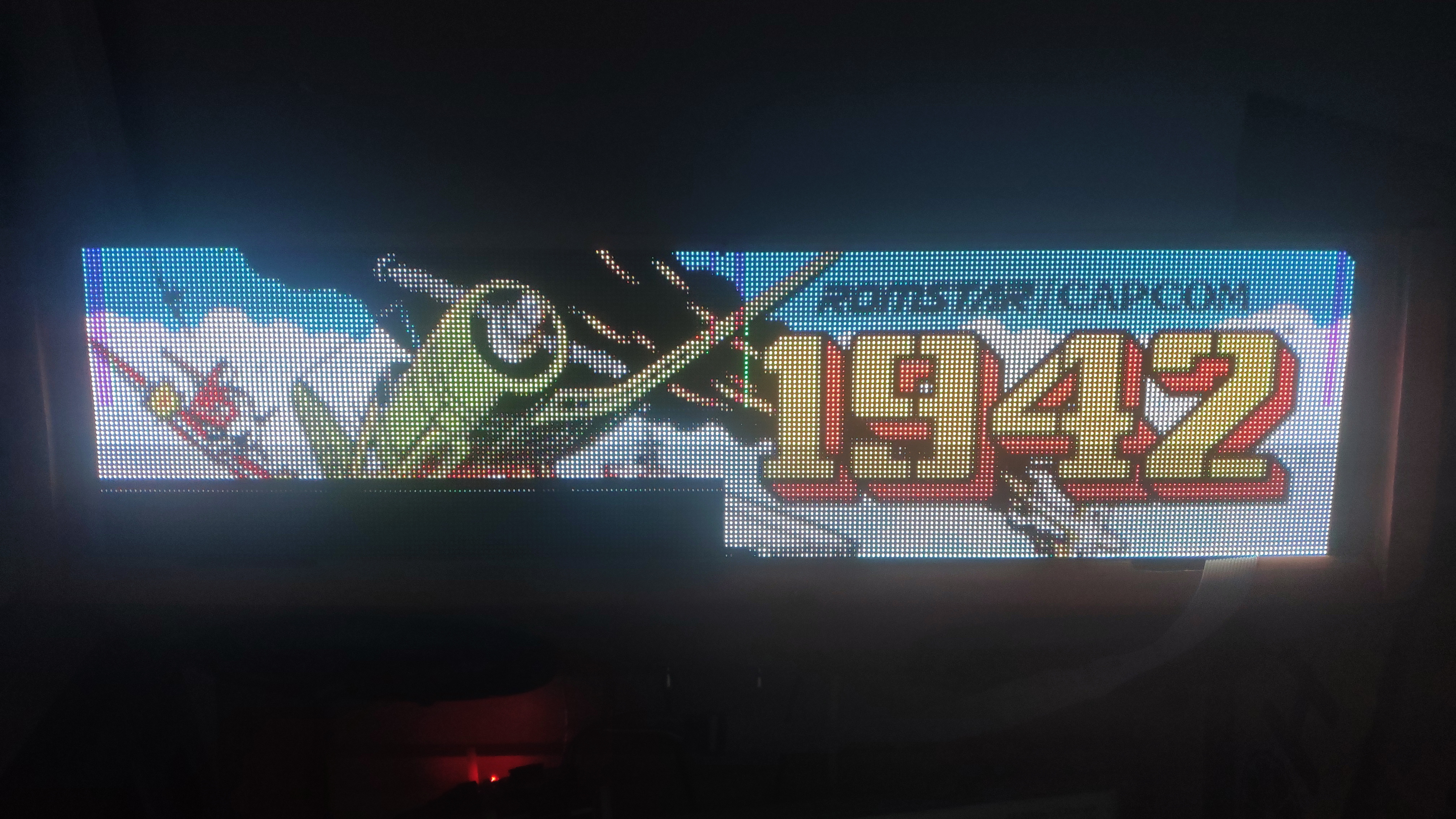
The broken pixels are surrounded in blue, the bad ones are in pink.
speaking of P2 panels and pixels that fall off, have you found some kind of glue spray that you can layer on top of them to glue them all in place so that they don't get lost? (and without affecting display quality and/or the space between panels if you put them adjacent to one another)
Good point @marcmerlin, this panels look very fragile and is very easy to lost pixels. (I found 2 of the pixels, but I don't know how to glue them to the panel again) In the other hand, I'm arguing with the seller because I think the panel arrived broken
@gustavoalara you need both. I also had a panel that was not protected correctly in shipping and arrived with some detached pixels, but trust me when I tell you that you will lose more unless you encase this in some way, or never touch/move it, so you might as well practice with the damaged panel :)
Epoxy resin maybe ? I might try with my already pixel missing panel to see if it renders the light & colors correctly with a thin layer of it.
Then, you thing the LEDs with incorrect colours are damaged too? Well, maybe if I'm lucky the seller will send me another panel and I can practice with the damaged panel as @marcmerlin said...
Mine is damaged too, I have one pixel with missig red color in the middle of the panel, and I'm pretty sure I received it with this pixel error. Sad. My other panels have much better quality. (but fragile too, because of small pixel size, but it is natural)
I know it's a little off topic but here's a little demo of the panel playing a video with VLC & sound enabled (using https://github.com/adafruit/rpi-fb-matrix). https://gofile.io/?c=F2Mp86
Ok, here is the fully functional SetRowAddress (no missing line), dear @hzeller please update the code
virtual void SetRowAddress(GPIO *io, int row) {
for (int activate = 0; activate < double_rows_; ++activate) {
io->ClearBits(clock_);
if (activate == double_rows_ - 1 - row) {
io->SetBits(data_);
} else {
io->ClearBits(data_);
}
io->SetBits(clock_);
}
io->SetBits(clock_);
io->ClearBits(clock_);
last_row_ = row;
}
I dont know why does it work, but work.
Awesome progress made here, thank you @mcpgza & @gustavoalara !
Hi!
The change proposed by @mcpgza works like a charm! My only problem now is the dead and malfunctioning pixels
For dead pixels, in the future, I was told to consider this https://www.amazon.com/gp/product/B0009GXMJG not sure how well it works
@marcmerlin If you need the LED to be functional, I think you'd need to hot air rework the connections, or replace the LED:
@embedded-creations nice. I wasn't the one who lost pixels on those panels (but I lost some on another panel, that were already detached when the panel arrived in the mail), but while I'm impressed by the work done to fix them, that's a bit beyond my equipment/skill level for the moment. I'll focus on trying to find the right glue spray to put on top of the entire panels when I receive them so that hopefully I don't lose pixels to start with. My immediate problem with my wearable panels is that because they are flexible, even the slight flex they receive eventually messes solder joints of the chips in the back, making me lose entire columns or rows depending on which pad gets disconnected (not in a visible way). Thankfully it's usually only one color component, so I don't lose the entire pixel, but it's still annoying. This is out of topic for this bug, so I opened a new discussion here https://community.pixelmatix.com/t/rgb-panels-and-wear-issues-losing-pixels-and-losing-solder-joints-in-the-back-on-flexible-panels/530
Amazing work @mcpgza !! Did the final working code get officially updated by @hzeller yet?
Now it is :) Thanks @mcpgza !
@mcpgza @hzeller I've only been able to try my ABC panels (really AC from what you said) now. It works great with --led-row-addr-type=3 --led-panel-type=FM6126A BTW, @hzeller I can confirm --led-panel-type=FM6126A works with the active parallel board, both my panels were initialized perfectly.
Guys, I am pretty new to all of this. However, I have the datasheet for the ICN2037 in English. Would that be of interest/help to anybody?
It looks like the main feature it adds over a standard LED shift register/column driver is that it has "dual latch for higher refresh rate". Maybe that can confirm how @mcpgza got the ABC LED panel to light up properly.
@mcpgza @bk313 @gustavoalara @5onix can I ask you to have a look at https://github.com/hzeller/rpi-rgb-led-matrix/issues/985 (I'm somehow not allowed to @ you in that issue). Long story short, ABC works fine, but it's slower than ABCDE, which it shouldn't be.
@whiteshavedchocolate this bug is about ABCDE vs ABC. Using the wrong led-row-addr-type still lights up fine, but displays lines in the wrong places. ICN2037 vs FM6126A is a shift register issue, and not related to led-row-addr-type What is the exactly problem you have and you're trying to fix?
I don't currently have a problem. I am learning and interested in hardware development around these Chinese LED panels. I am willing to help where I can, but my skills are in hardware and very limited in software/firmware.
On Thu, Feb 13, 2020, 7:57 PM Marc MERLIN notifications@github.com wrote:
@whiteshavedchocolate https://github.com/whiteshavedchocolate this bug is about ABCDE vs ABC. Using the wrong led-row-addr-type still lights up fine, but displays lines in the wrong places. ICN2037 vs FM6126A is a shift register issue, and not related to led-row-addr-type What is the exactly problem you have and you're trying to fix?
— You are receiving this because you were mentioned. Reply to this email directly, view it on GitHub https://github.com/hzeller/rpi-rgb-led-matrix/issues/823?email_source=notifications&email_token=AE2B5RAPMPC7VVGKOT7RPSLRCXT7NA5CNFSM4HPVN5EKYY3PNVWWK3TUL52HS4DFVREXG43VMVBW63LNMVXHJKTDN5WW2ZLOORPWSZGOELXFUBI#issuecomment-586045957, or unsubscribe https://github.com/notifications/unsubscribe-auth/AE2B5RDTLATA24CILHQYQWLRCXT7NANCNFSM4HPVN5EA .
@whiteshavedchocolate ok, then there is no problem at the moment, ICN2037 seems to work fine as is (unless I missed something)
FWIW the current code implements 33 clocks into the shift register (an extra clock at the end), but I found that 32 clocks is correct for my FPGA reimplementation. I'm wondering if the last clock is fast enough that it's getting missed. (the last clock actually looks like a leftover from the old version with inverted clock polarity).
@mcpgza @bk313 @gustavoalara @5onix can I ask you where you bought your panels from, and what you paid for them? My current supplier is offering them at $50 per panel (shipped from china), and unfortunately he says he can only sell ABC, as ABCDE doesn't seem to be available anymore. I'm looking at 64x128 P2 panels. I'm a bit bummed about having to use ABC panels with a lower refresh rate, but if that's all what is available today, and $50/panel is about the right price, so be it, I'll go ahead and get those (I need 8, so making sure before I plop down $400 on this)
@marcmerlin I bought theese: https://www.aliexpress.com/item/32998082589.html ABC panels, not perfect panels, some of them seem used, some have missing leds on the edge, but generally i'm happy with them for this price. I bout 8, but i can drive only 6 using RaspberryPi 4, with resolution 256x192. Max refresh rate with this config is 80Hz, which is more or less enough.
But why do you think that ABC panels are slower then ABCDE?
Thanks @mcpgza . I'll probably pay a bit more for pristine panels, I don't want missing pixels for my setup :) https://github.com/hzeller/rpi-rgb-led-matrix/issues/985 explains why ABC is slower than ABCDE. In a nutshell, ABC panels are ABCDE panels with 2 address lines missing, so it takes longer to send the 5 bits of addresses over 3 bits. you can benchmark this yourself with ~/rpi-rgb-led-matrix/examples-api-use/demo --led-rows=64 --led-cols=128 --led-chain=1 --led-show-refresh --led-parallel=3 --led-pwm-dither-bits=1 --led-pwm-bits=7 --led-panel-type=FM6126A --led-row-addr-type=0 -D0 and then use led-row-addr-type=3 You can do the speed test even without the right panels and look at the Hz value you get.
This is starting to get annoying... I get output on them after sending the fm26126A init sequence, but the output is all wrong given the line addressing having changed again. It seems that you only select one of 8 lines, and push 4 times 128 pixels to reach the other 3 rows after filling the first one. Why, oh why do "they" have to keep changing how to do things? I got those as replacements for a perfectly working ABCDE panel